NISSAN X-TRAIL 2001 Service Repair Manual
Manufacturer: NISSAN, Model Year: 2001, Model line: X-TRAIL, Model: NISSAN X-TRAIL 2001Pages: 3833, PDF Size: 39.49 MB
Page 3221 of 3833
EI-1
EXTERIOR & INTERIOR
I BODY
CONTENTS
C
D
E
F
G
H
J
K
L
M
SECTION
A
B
EI
EXTERIOR & INTERIOR
PRECAUTIONS .......................................................... 2
Precautions for Supplemental Restraint System
(SRS) “AIR BAG” and “SEAT BELT PRE-TEN-
SIONER” .................................................................. 2
Precautions .............................................................. 2
CLIP AND FASTENER ............................................... 3
Clip and Fastener ..................................................... 3
FRONT BUMPER ....................................................... 6
Removal and Installation .......................................... 6
REMOVAL ............................................................. 8
INSTALLATION ..................................................... 8
REAR BUMPER .................................................... ..... 9
Removal and Installation .......................................... 9
REMOVAL ............................................................. 9
INSTALLATION ................................................... 10
FRONT GRILLE .........................................................11
Removal and Installation ......................................... 11
REMOVAL ............................................................ 11
INSTALLATION .................................................... 11
COWL TOP ............................................................... 12
Removal and Installation ........................................ 12
REMOVAL ........................................................... 12
INSTALLATION ................................................... 12
FENDER PROTECTOR ............................................ 13
Removal and Installation ........................................ 13
DOOR OUTSIDE MOLDING .................................... 14
Removal and Installation ........................................ 14
REMOVAL ........................................................... 14
INSTALLATION ................................................... 15
SIDE GUARD MOLDING .......................................... 16
Removal and Installation ........................................ 16
DOOR OUTSIDE LOWER MOLDING ...................... 17
Removal and Installation ........................................ 17
SIDE SILL PROTECTOR .......................................... 18
Removal and Installation ........................................ 18ROOF RAIL ............................................................... 19
Removal and Installation ........................................ 19
REMOVAL ........................................................... 19
INSTALLATION ................................................... 20
ROOF SPOILER ....................................................... 21
Removal and Installation ........................................ 21
REMOVAL ........................................................... 21
INSTALLATION ................................................... 21
LICENSE LAMP FINISHER ...................................... 22
Removal and Installation ........................................ 22
REMOVAL ........................................................... 22
INSTALLATION ................................................... 22
DOOR FINISHER ...................................................... 23
Removal and Installation ........................................ 23
FRONT AND REAR ............................................ 23
BACK DOOR TRIM ................................................... 25
Removal and Installation ........................................ 25
BODY SIDE TRIM ..................................................... 26
Removal and Installation ........................................ 26
CENTER PILLAR LOWER GARNISH ................. 26
CENTER PILLAR UPPER GARNISH .................. 27
LUGGAGE SIDE LOWER FINISHER ................. 27
REAR PILLAR FINISHER ................................... 27
DASHBOARD SIDE FINISHER .......................... 27
BODY SIDE WELT .............................................. 27
FLOOR TRIM ............................................................ 28
Removal and Installation ........................................ 28
REMOVAL ........................................................... 28
INSTALLATION ................................................... 28
HEADLINING ............................................................ 29
Removal and Installation ........................................ 29
REMOVAL ........................................................... 29
INSTALLATION ................................................... 30
Page 3222 of 3833
EI-2
PRECAUTIONS
PRECAUTIONS
PFP:00001
Precautions for Supplemental Restraint System (SRS) “AIR BAG” and “SEAT
BELT PRE-TENSIONER”
EIS0047M
The Supplemental Restraint System such as “AIR BAG” and “SEAT BELT PRE-TENSIONER”, used along
with a front seat belt, helps to reduce the risk or severity of injury to the driver and front passenger for certain
types of collision. Information necessary to service the system safely is included in the SRS and SB section of
this Service Manual.
WARNING:
●To avoid rendering the SRS inoperative, which could increase the risk of personal injury or death
in the event of a collision which would result in air bag inflation, all maintenance must be per-
formed by an authorized NISSAN/INFINITI dealer.
●Improper maintenance, including incorrect removal and installation of the SRS, can lead to per-
sonal injury caused by unintentional activation of the system. For removal of Spiral Cable and Air
Bag Module, see the SRS section.
●Do not use electrical test equipment on any circuit related to the SRS unless instructed to in this
Service Manual. SRS wiring harnesses can be identified by yellow and/or orange harness connec-
tors.
Precautions EIS001NX
●When removing or disassembling any part, be careful not to damage or deform it. Protect parts, which
may get in the way with cloth.
●When removing parts with a screwdriver or other tool, protect parts by wrapping them with vinyl or tape.
●Keep removed parts protected with cloth.
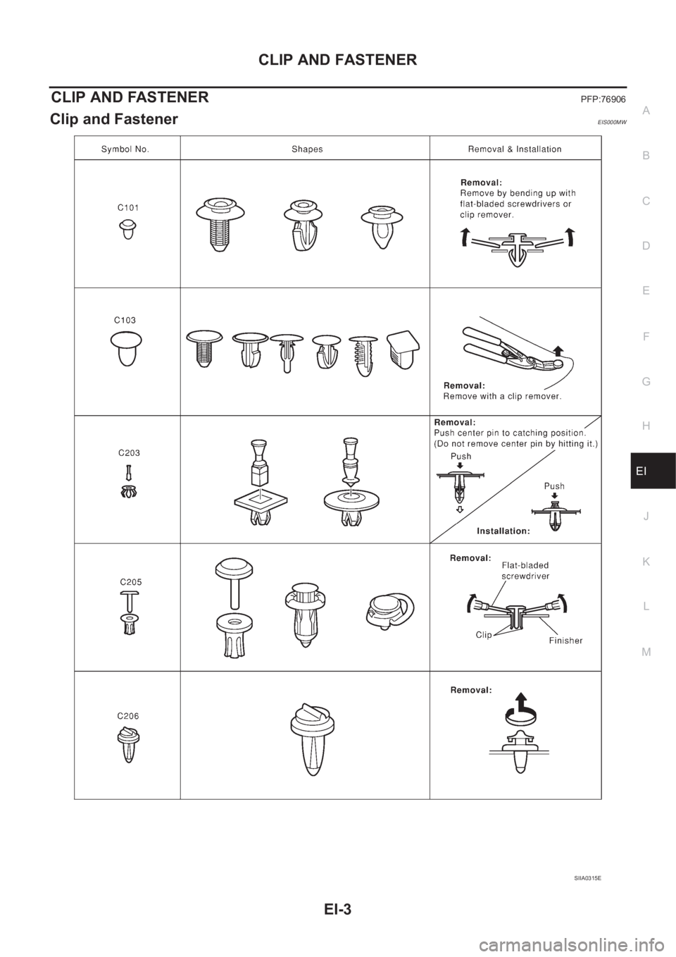
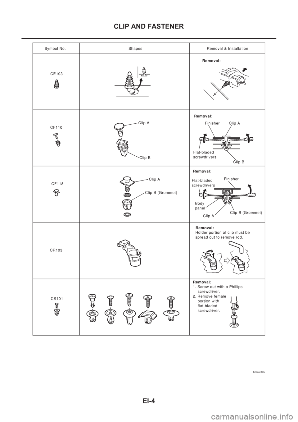
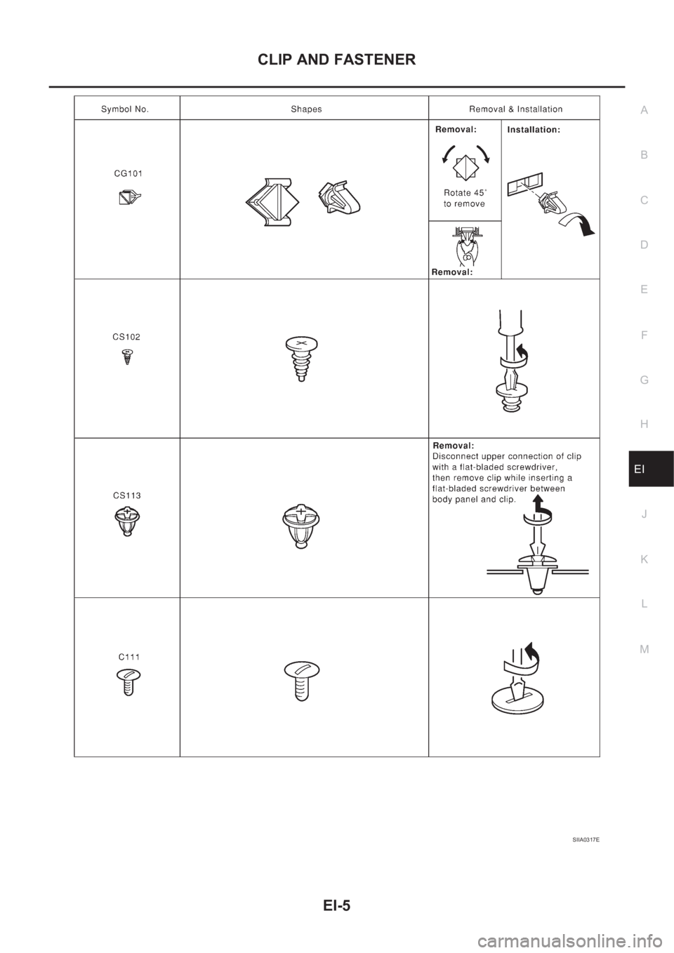
●If a clip is deformed or damaged, replace it.
●If an unreusable part is removed, replace it with a new one.
●Tighten bolts and nuts firmly to the specified torque.
●After re-assembly has been completed, make sure each part functions correctly.
●Remove stains in the following way.
Water-soluble stains:
Dip a soft cloth in warm water, and then squeeze it tightly. After wiping the stain, wipe with a soft dry cloth.
Oil stain:
Dissolve a synthetic detergent in warm water (density of 2 to 3% or less), dip the cloth, then clean off the stain
with the cloth. Next, dip the cloth in fresh water and squeeze it tightly. Then clean off the detergent completely.
Then wipe the area with a soft dry cloth.
●Do not use any organic solvent, such as thinner or benzine.
Page 3223 of 3833
CLIP AND FASTENER
EI-3
C
D
E
F
G
H
J
K
L
MA
B
EI
CLIP AND FASTENERPFP:76906
Clip and FastenerEIS000MW
SIIA0315E
Page 3224 of 3833
EI-4
CLIP AND FASTENER
SIIA0316E
Page 3225 of 3833
CLIP AND FASTENER
EI-5
C
D
E
F
G
H
J
K
L
MA
B
EI
SIIA0317E
Page 3226 of 3833
EI-6
FRONT BUMPER
FRONT BUMPER
PFP:F2022
Removal and InstallationEIS000MX
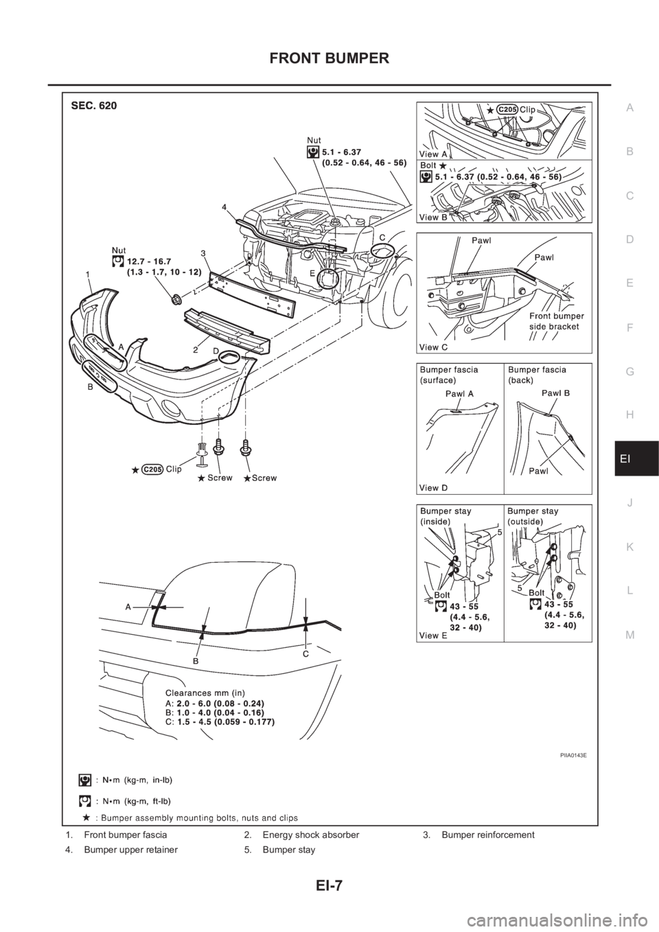
●Bumper fascia is made of resin. Do not apply strong force to it, and be careful to prevent contact with oil.
Page 3227 of 3833
FRONT BUMPER
EI-7
C
D
E
F
G
H
J
K
L
MA
B
EI
1. Front bumper fascia 2. Energy shock absorber 3. Bumper reinforcement
4. Bumper upper retainer 5. Bumper stay
PIIA0143E
Page 3228 of 3833
EI-8
FRONT BUMPER
REMOVAL
1. Remove front grille. Refer to EI-11, "Removal and Installation" .
2. Remove mounting screws and clips on RH/LH front fender protector.
3. Remove front bumper fascia mounting screws from RH/LH front fender.
4. Remove clips from the top surface of front bumper and bolts from the lower surface.
5. Press down tabs A (1 each on left/right sides) on bumper fascia to remove. Then disengage tabs B (1
each on left/right sides) on the fender and remove bumper fascia assembly.
6. Remove energy shock absorber.
7. Remove mounting nuts from bumper reinforcement assembly.
8. Remove mounting nuts from bumper upper retainer assembly.
9. Remove mounting bolts from bumper stay assembly.
INSTALLATION
Installation is in the reverse order of removal.
NOTE:
After installation, adjust the clearance.
Page 3229 of 3833
REAR BUMPER
EI-9
C
D
E
F
G
H
J
K
L
MA
B
EI
REAR BUMPERPFP:H5022
Removal and InstallationEIS000MY
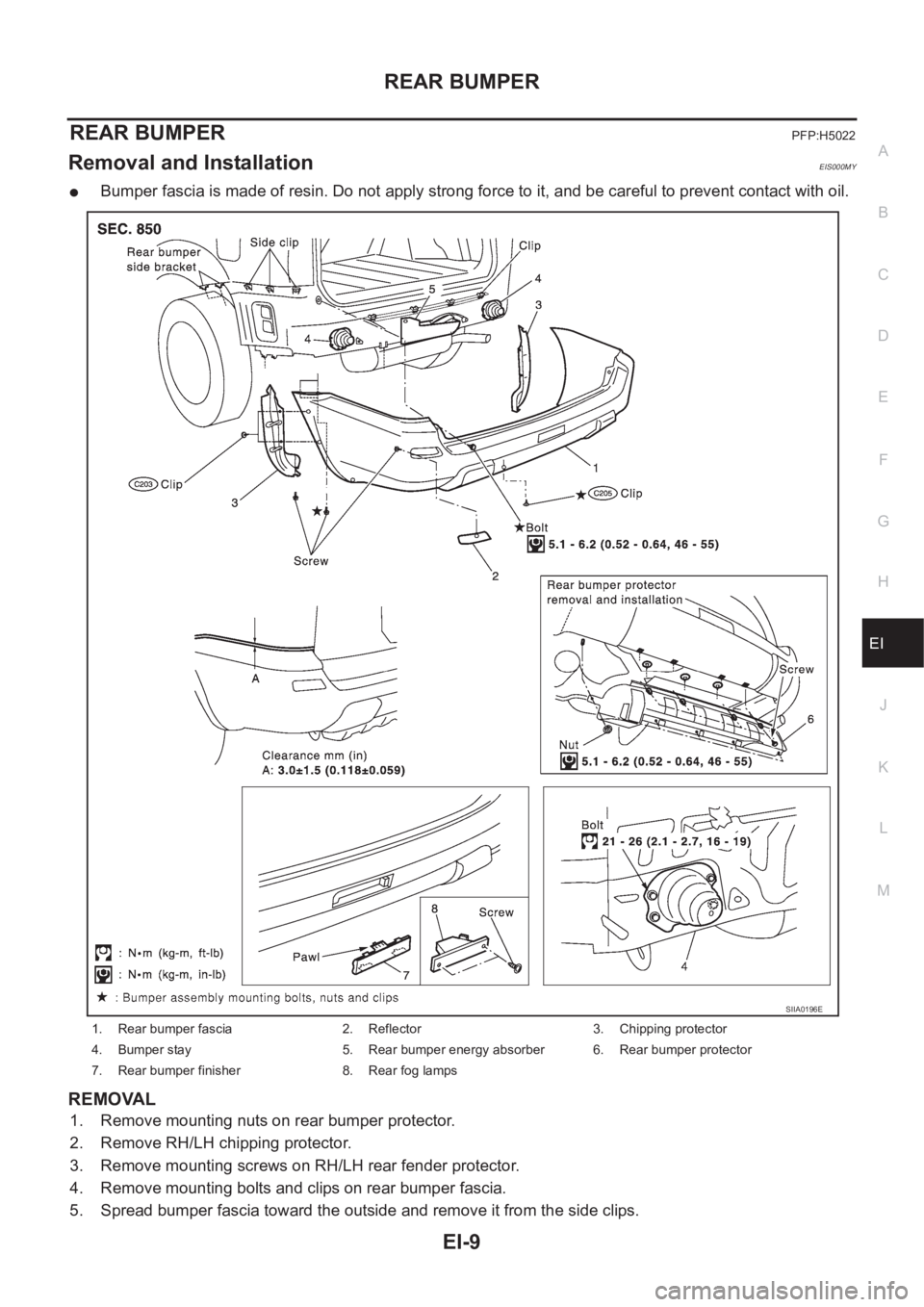
●Bumper fascia is made of resin. Do not apply strong force to it, and be careful to prevent contact with oil.
REMOVAL
1. Remove mounting nuts on rear bumper protector.
2. Remove RH/LH chipping protector.
3. Remove mounting screws on RH/LH rear fender protector.
4. Remove mounting bolts and clips on rear bumper fascia.
5. Spread bumper fascia toward the outside and remove it from the side clips.
1. Rear bumper fascia 2. Reflector 3. Chipping protector
4. Bumper stay 5. Rear bumper energy absorber 6. Rear bumper protector
7. Rear bumper finisher 8. Rear fog lamps
SIIA0196E
Page 3230 of 3833
EI-10
REAR BUMPER
6. Remove rear fog lamp connectors. Pull bumper fascia assembly straight rearward to remove.
7. Remove mounting bolts on bumper stay.
8. Remove rear bumper finisher, or rear fog lamps, and the reflectors from bumper.
INSTALLATION
Installation is in the reverse order of removal.
NOTE:
After installation, adjust the clearance.