NISSAN X-TRAIL 2001 Service Repair Manual
Manufacturer: NISSAN, Model Year: 2001, Model line: X-TRAIL, Model: NISSAN X-TRAIL 2001Pages: 3833, PDF Size: 39.49 MB
Page 3591 of 3833
COMBINATION METERS (RHD MODELS)
DI-33
C
D
E
F
G
H
I
J
L
MA
B
DI
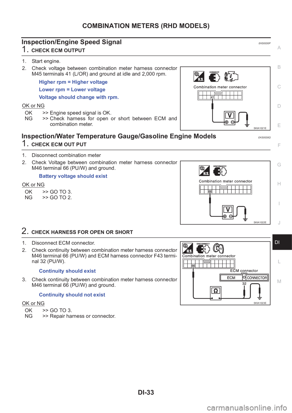
Inspection/Engine Speed SignalEKS0030P
1.CHECK ECM OUTPUT
1. Start engine.
2. Check voltage between combination meter harness connector
M45 terminals 41 (L/OR) and ground at idle and 2,000 rpm.
OK or NG
OK >> Engine speed signal is OK.
NG >> Check harness for open or short between ECM and
combination meter.
Inspection/Water Temperature Gauge/Gasoline Engine ModelsEKS0030Q
1.CHECK ECM OUT PUT
1. Disconnect combination meter
2. Check Voltage between combination meter harness connector
M46 terminal 66 (PU/W) and ground.
OK or NG
OK >> GO TO 3.
NG >> GO TO 2.
2.CHECK HARNESS FOR OPEN OR SHORT
1. Disconnect ECM connector.
2. Check continuity between combination meter harness connector
M46 terminal 66 (PU/W) and ECM harness connector F43 termi-
nal 32 (PU/W).
3. Check continuity between combination meter harness connector
M46 terminal 66 (PU/W) and ground.
OK or NG
OK >> GO TO 3.
NG >> Repair harness or connector.Higher rpm = Higher voltage
Lower rpm = Lower voltage
Voltage should change with rpm.
SKIA1021E
Battery voltage should exist
SKIA1022E
Continuity should exist
Continuity should not exist
SKIA1023E
Page 3592 of 3833
DI-34
COMBINATION METERS (RHD MODELS)
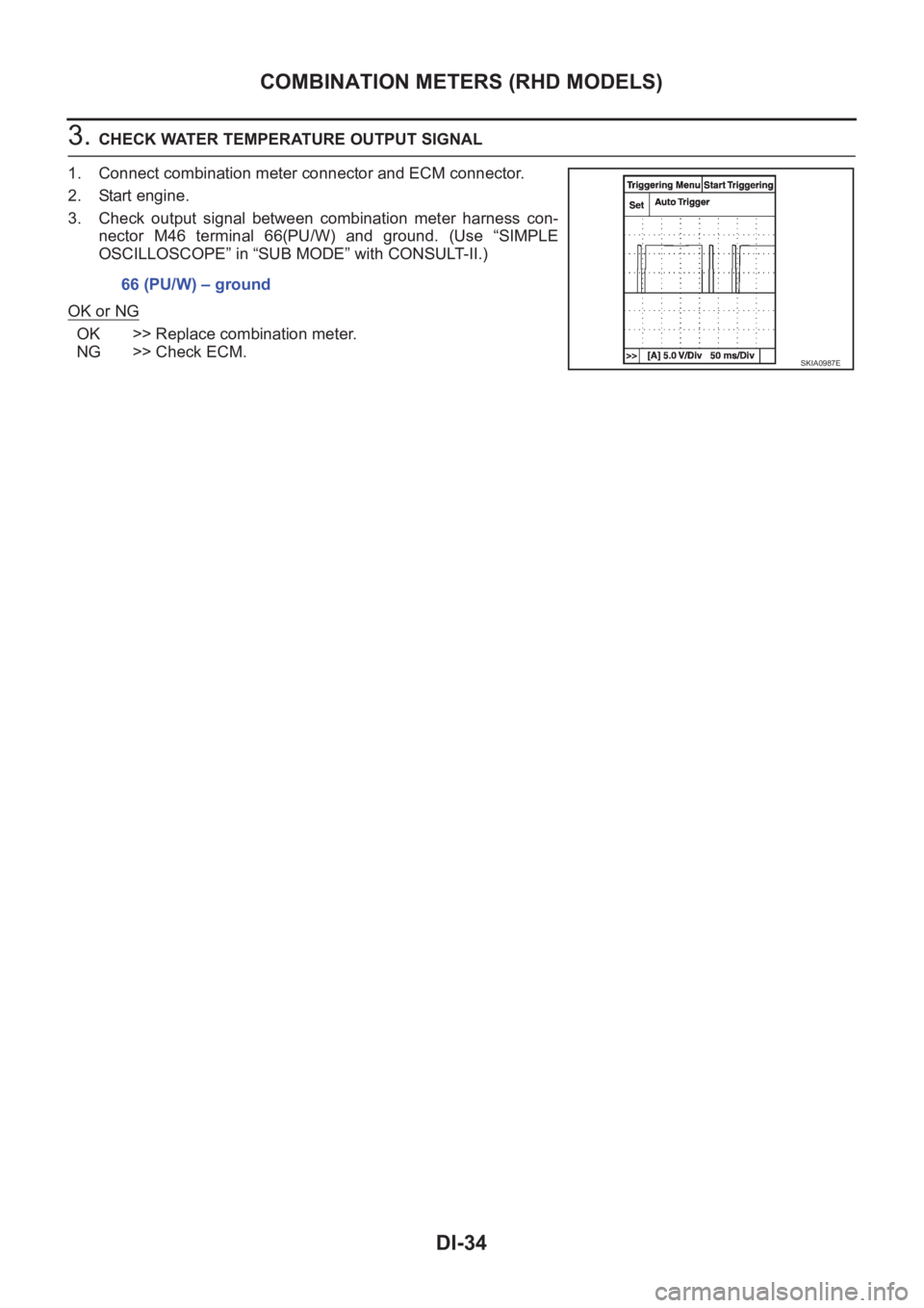
3. CHECK WATER TEMPERATURE OUTPUT SIGNAL
1. Connect combination meter connector and ECM connector.
2. Start engine.
3. Check output signal between combination meter harness con-
nector M46 terminal 66(PU/W) and ground. (Use “SIMPLE
OSCILLOSCOPE” in “SUB MODE” with CONSULT-II.)
OK or NG
OK >> Replace combination meter.
NG >> Check ECM.66 (PU/W) – ground
SKIA0987E
Page 3593 of 3833
COMBINATION METERS (RHD MODELS)
DI-35
C
D
E
F
G
H
I
J
L
MA
B
DI
Inspection/Water Temperature Gauge/Diesel Engine ModelsEKS0030R
1.CHECK THERMAL TRANSMITTER
Refer to DI-42, "
THERMAL TRANSMITTER CHECK" .
OK or NG
OK >> GO TO 2.
NG >> Replace thermal transmitter.
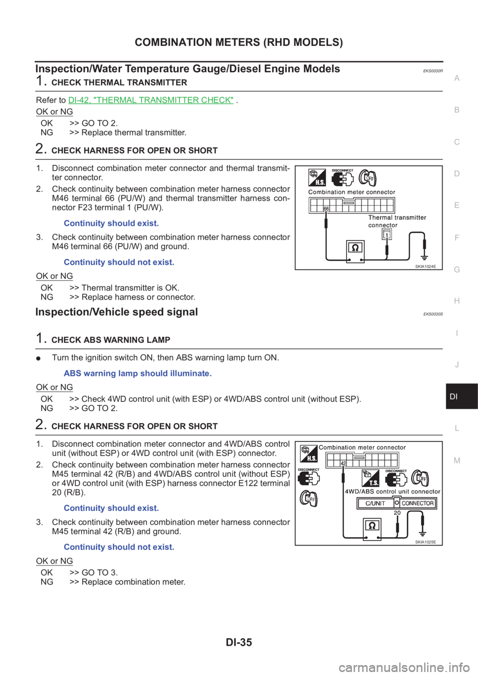
2.CHECK HARNESS FOR OPEN OR SHORT
1. Disconnect combination meter connector and thermal transmit-
ter connector.
2. Check continuity between combination meter harness connector
M46 terminal 66 (PU/W) and thermal transmitter harness con-
nector F23 terminal 1 (PU/W).
3. Check continuity between combination meter harness connector
M46 terminal 66 (PU/W) and ground.
OK or NG
OK >> Thermal transmitter is OK.
NG >> Replace harness or connector.
Inspection/Vehicle speed signalEKS0030S
1.CHECK ABS WARNING LAMP
●Turn the ignition switch ON, then ABS warning lamp turn ON.
OK or NG
OK >> Check 4WD control unit (with ESP) or 4WD/ABS control unit (without ESP).
NG >> GO TO 2.
2.CHECK HARNESS FOR OPEN OR SHORT
1. Disconnect combination meter connector and 4WD/ABS control
unit (without ESP) or 4WD control unit (with ESP) connector.
2. Check continuity between combination meter harness connector
M45 terminal 42 (R/B) and 4WD/ABS control unit (without ESP)
or 4WD control unit (with ESP) harness connector E122 terminal
20 (R/B).
3. Check continuity between combination meter harness connector
M45 terminal 42 (R/B) and ground.
OK or NG
OK >> GO TO 3.
NG >> Replace combination meter.Continuity should exist.
Continuity should not exist.
SKIA1024E
ABS warning lamp should illuminate.
Continuity should exist.
Continuity should not exist.
SKIA1025E
Page 3594 of 3833
DI-36
COMBINATION METERS (RHD MODELS)
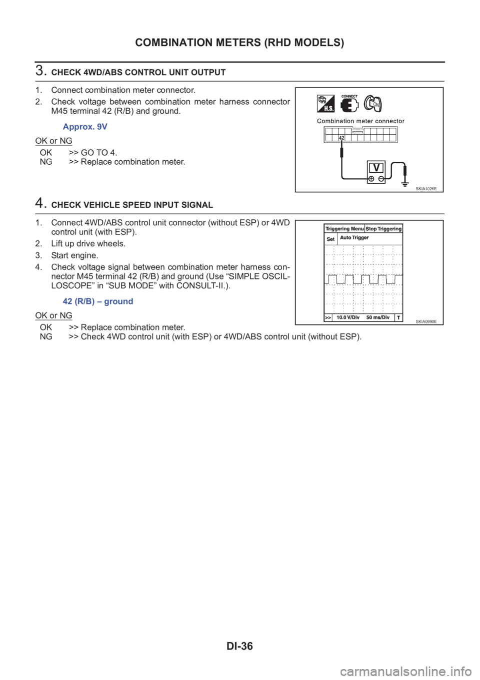
3. CHECK 4WD/ABS CONTROL UNIT OUTPUT
1. Connect combination meter connector.
2. Check voltage between combination meter harness connector
M45 terminal 42 (R/B) and ground.
OK or NG
OK >> GO TO 4.
NG >> Replace combination meter.
4. CHECK VEHICLE SPEED INPUT SIGNAL
1. Connect 4WD/ABS control unit connector (without ESP) or 4WD
control unit (with ESP).
2. Lift up drive wheels.
3. Start engine.
4. Check voltage signal between combination meter harness con-
nector M45 terminal 42 (R/B) and ground (Use “SIMPLE OSCIL-
LOSCOPE” in “SUB MODE” with CONSULT-II.).
OK or NG
OK >> Replace combination meter.
NG >> Check 4WD control unit (with ESP) or 4WD/ABS control unit (without ESP). Approx. 9V
SKIA1026E
42 (R/B) – ground
SKIA0990E
Page 3595 of 3833
COMBINATION METERS (RHD MODELS)
DI-37
C
D
E
F
G
H
I
J
L
MA
B
DI
Inspection/Fuel Level Sensor UnitEKS0030T
FUEL LEVEL SENSOR UNIT
The following symptoms do not indicate a malfunction.
●Depending on vehicle posture or driving circumstance, the fuel level in the tank varies, and the pointer
may fluctuate.
●If the vehicle is fueled with the ignition switch ON, the pointer will move slowly.
LOW-FUEL WARNING LAMP
Depending on vehicle posture or driving circumstance, the fuel level in the tank varies, and the warning lamp
ON timing may be changed.
1.DIAGNOSIS MODE INSPECTION
Preform the combination meter diagnosis mode. Refer to DI-30, "
Meter/Gauge Operation and Odo/Trip Meter
Segment Check in Diagnosis Mode" .
OK or NG
OK >> GO TO 2.
NG >> Replace combination meter.
2.HARNESS CONNECTOR INSPECTION
1. Turn the ignition switch OFF.
2. Check combination meter, fuel level sensor unit and terminals (meter-side, module-side, and harness-
side) for poor connection and bend.
OK or NG
OK >> GO TO 3.
NG >> Repair terminals or connectors.
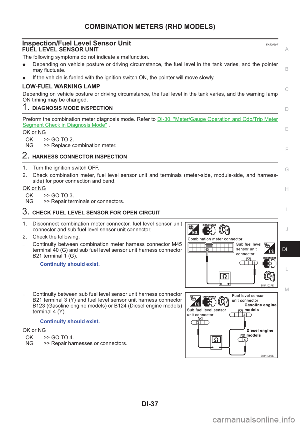
3.CHECK FUEL LEVEL SENSOR FOR OPEN CIRCUIT
1. Disconnect combination meter connector, fuel level sensor unit
connector and sub fuel level sensor unit connector.
2. Check the following.
–Continuity between combination meter harness connector M45
terminal 40 (G) and sub fuel level sensor unit harness connector
B21 terminal 1 (G).
–Continuity between sub fuel level sensor unit harness connector
B21 terminal 3 (Y) and fuel level sensor unit harness connector
B123 (Gasoline engine models) or B124 (Diesel engine models)
terminal 4 (Y).
OK or NG
OK >> GO TO 4.
NG >> Repair harnesses or connectors.Continuity should exist.
SKIA1027E
Continuity should exist.
SKIA1005E
Page 3596 of 3833
DI-38
COMBINATION METERS (RHD MODELS)
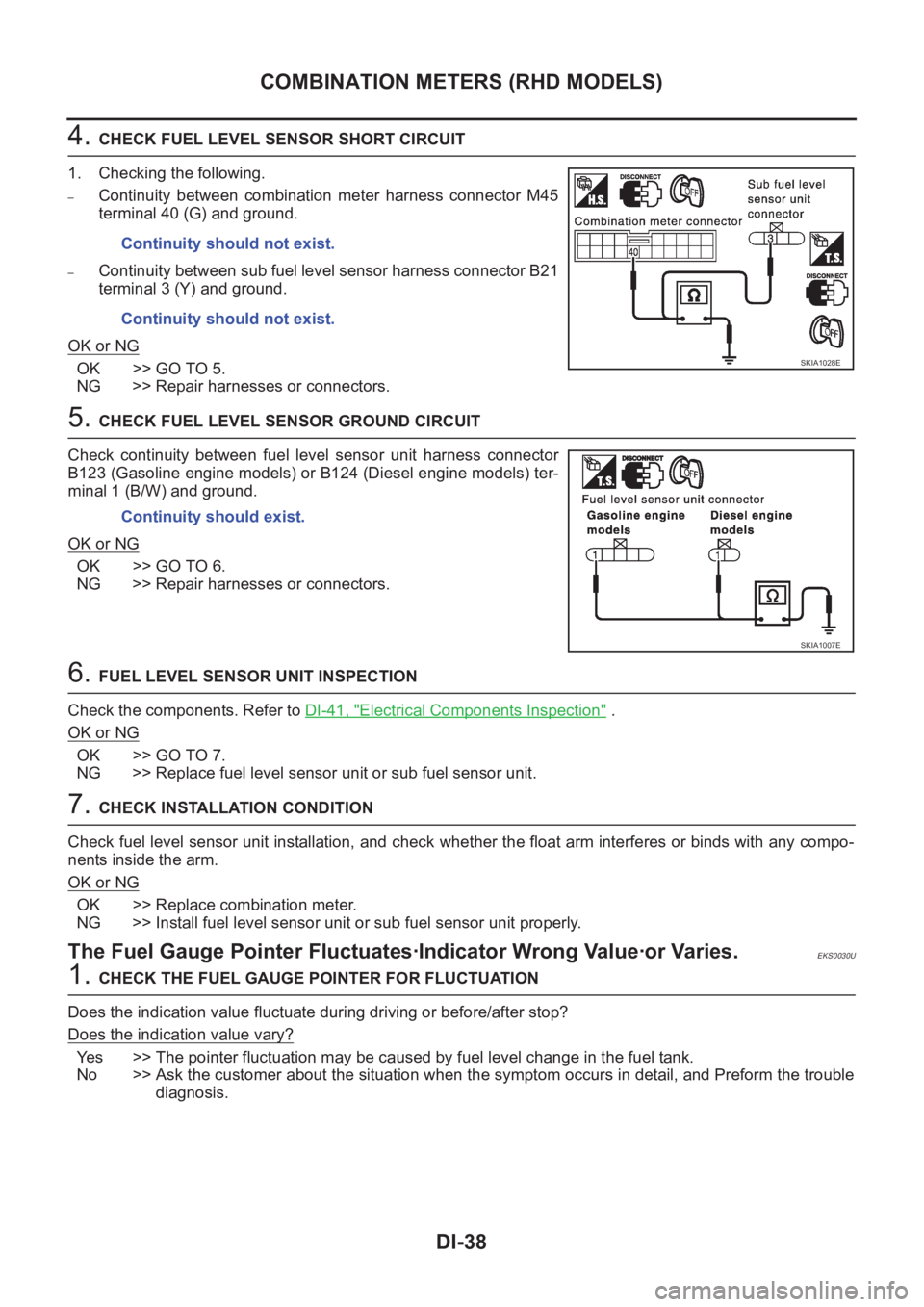
4. CHECK FUEL LEVEL SENSOR SHORT CIRCUIT
1. Checking the following.
–Continuity between combination meter harness connector M45
terminal 40 (G) and ground.
–Continuity between sub fuel level sensor harness connector B21
terminal 3 (Y) and ground.
OK or NG
OK >> GO TO 5.
NG >> Repair harnesses or connectors.
5. CHECK FUEL LEVEL SENSOR GROUND CIRCUIT
Check continuity between fuel level sensor unit harness connector
B123 (Gasoline engine models) or B124 (Diesel engine models) ter-
minal 1 (B/W) and ground.
OK or NG
OK >> GO TO 6.
NG >> Repair harnesses or connectors.
6. FUEL LEVEL SENSOR UNIT INSPECTION
Check the components. Refer to DI-41, "
Electrical Components Inspection" .
OK or NG
OK >> GO TO 7.
NG >> Replace fuel level sensor unit or sub fuel sensor unit.
7. CHECK INSTALLATION CONDITION
Check fuel level sensor unit installation, and check whether the float arm interferes or binds with any compo-
nents inside the arm.
OK or NG
OK >> Replace combination meter.
NG >> Install fuel level sensor unit or sub fuel sensor unit properly.
The Fuel Gauge Pointer Fluctuates·Indicator Wrong Value·or Varies.EKS0030U
1. CHECK THE FUEL GAUGE POINTER FOR FLUCTUATION
Does the indication value fluctuate during driving or before/after stop?
Does the indication value vary?
Yes >> The pointer fluctuation may be caused by fuel level change in the fuel tank.
No >> Ask the customer about the situation when the symptom occurs in detail, and Preform the trouble
diagnosis. Continuity should not exist.
Continuity should not exist.
SKIA1028E
Continuity should exist.
SKIA1007E
Page 3597 of 3833
COMBINATION METERS (RHD MODELS)
DI-39
C
D
E
F
G
H
I
J
L
MA
B
DI
The Fuel Gauge Does Not Move to Full-position.EKS0030V
1.QUESTION 1
Does it take a long time for the pointer to move to Full-position?
Ye s o r N o
Ye s > > G O T O 2 .
No >> GO TO 3.
2.QUESTION 2
Was the vehicle fueled with the ignition switch ON?
Ye s o r N o
Yes >> Be sure to fuel the vehicle with the ignition switch OFF. Otherwise it will take a long time to move
to Full-position because of the characteristic of the fuel gauge.
No >> GO TO 3.
3.QUESTION 3
Is the floor or the vehicle inclined?
Ye s o r N o
Yes >> It may not be filled fully.
No >> GO TO 4.
4.QUESTION 4
During driving, does the fuel gauge pointer move gradually toward E-position?
Ye s o r N o
Yes >> Check the components. Refer to DI-41, "Electrical Components Inspection" .
No >> The float arm may interfere or bind with any of the components in the fuel tank.
The Fuel Gauge Does Not Work.EKS0030W
1.HARNESS CONNECTOR INSPECTION
1. Turn the ignition switch OFF.
2. Check combination meter, fuel level sensor unit, sub fuel level sensor unit and terminals (meter-side,
module-side, and harness-side) for poor connection and bend.
OK or NG
OK >> GO TO 2.
NG >> Repair connector.
2.CHECK INSTALLATION CONDITION
Check fuel level sensor unit or sub fuel level sensor unit installation (refer toFL-4, "
FUEL LEVEL SENSOR
UNIT, FUEL FILTER AND FUEL PUMP ASSEMBLY" for QR engine models or FL-17, "FUEL LEVEL SEN-
SOR UNIT" for YD engine models, and check whether the float arm interferes or binds with any components
inside the arm.
OK or NG
OK >> Fuel level sensor unit is OK.
NG >> Check fuel level sensor unit or sub fuel level sensor unit. Refer to DI-41, "
Electrical Components
Inspection" .
Page 3598 of 3833
DI-40
COMBINATION METERS (RHD MODELS)
Low Fuel Warning Lamp Illuminate or Not Illuminate
EKS0030X
1. DIAGNOSIS MODE INSPECTION
Preform combination meter diagnosis mode. Refer to DI-30, "
Meter/Gauge Operation and Odo/Trip Meter
Segment Check in Diagnosis Mode" .
OK or NG
OK >> Check fuel level sensor unit or sub fuel level sensor unit. Refer to DI-41, "Electrical Components
Inspection" .
NG >> Replace combination meter.
Page 3599 of 3833
COMBINATION METERS (RHD MODELS)
DI-41
C
D
E
F
G
H
I
J
L
MA
B
DI
Electrical Components InspectionEKS0031V
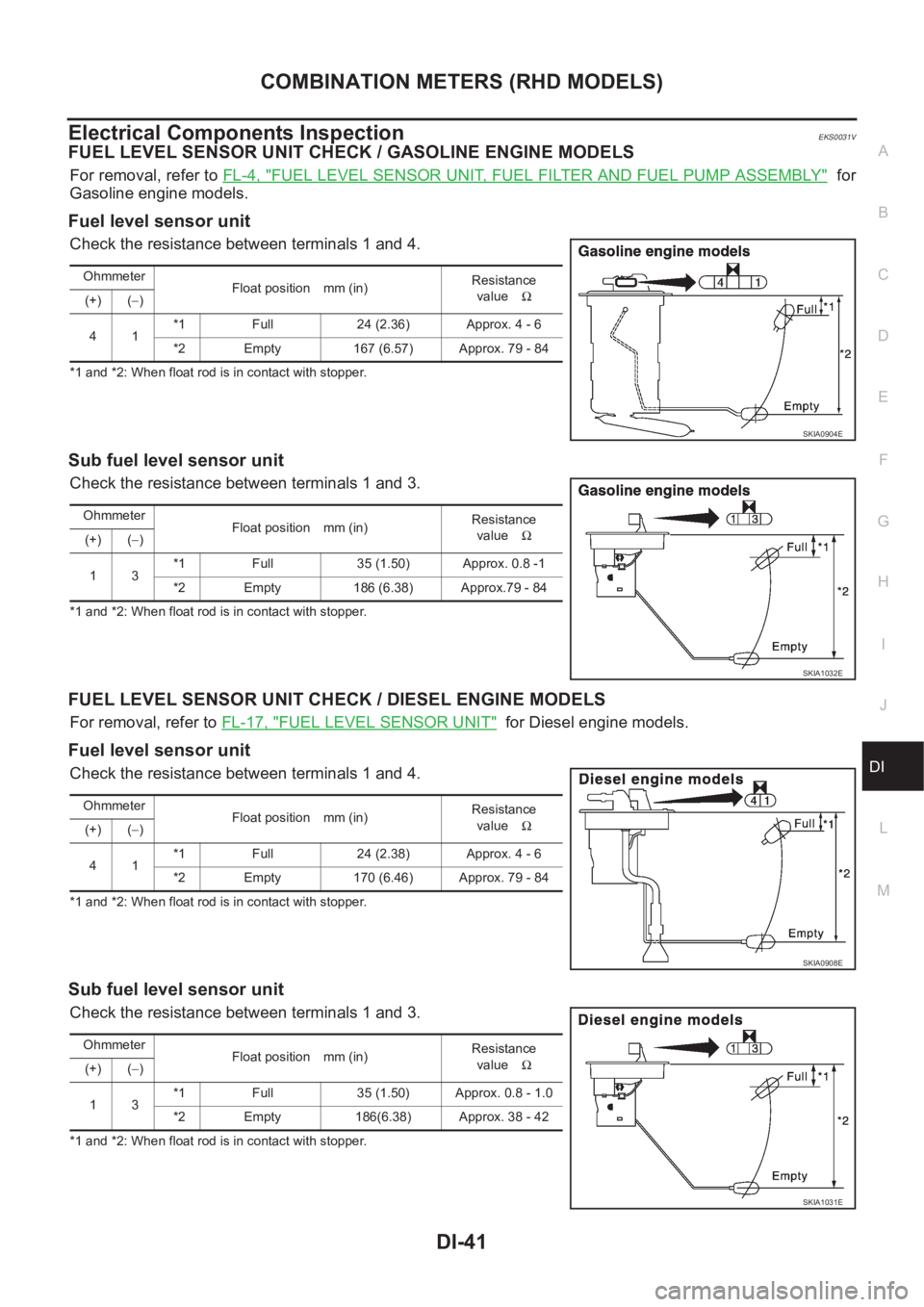
FUEL LEVEL SENSOR UNIT CHECK / GASOLINE ENGINE MODELS
For removal, refer to FL-4, "FUEL LEVEL SENSOR UNIT, FUEL FILTER AND FUEL PUMP ASSEMBLY" for
Gasoline engine models.
Fuel level sensor unit
Check the resistance between terminals 1 and 4.
*1 and *2: When float rod is in contact with stopper.
Sub fuel level sensor unit
Check the resistance between terminals 1 and 3.
*1 and *2: When float rod is in contact with stopper.
FUEL LEVEL SENSOR UNIT CHECK / DIESEL ENGINE MODELS
For removal, refer to FL-17, "FUEL LEVEL SENSOR UNIT" for Diesel engine models.
Fuel level sensor unit
Check the resistance between terminals 1 and 4.
*1 and *2: When float rod is in contact with stopper.
Sub fuel level sensor unit
Check the resistance between terminals 1 and 3.
*1 and *2: When float rod is in contact with stopper.Ohmmeter
Float position mm (in)Resistance
valueΩ
(+) (−)
41*1 Full 24 (2.36) Approx. 4 - 6
*2 Empty 167 (6.57) Approx. 79 - 84
SKIA0904E
Ohmmeter
Float position mm (in)Resistance
valueΩ
(+) (−)
13*1 Full 35 (1.50) Approx. 0.8 -1
*2 Empty 186 (6.38) Approx.79 - 84
SKIA1032E
Ohmmeter
Float position mm (in)Resistance
valueΩ
(+) (−)
41*1 Full 24 (2.38) Approx. 4 - 6
*2 Empty 170 (6.46) Approx. 79 - 84
SKIA0908E
Ohmmeter
Float position mm (in)Resistance
valueΩ
(+) (−)
13*1 Full 35 (1.50) Approx. 0.8 - 1.0
*2 Empty 186(6.38) Approx. 38 - 42
SKIA1031E
Page 3600 of 3833
DI-42
COMBINATION METERS (RHD MODELS)
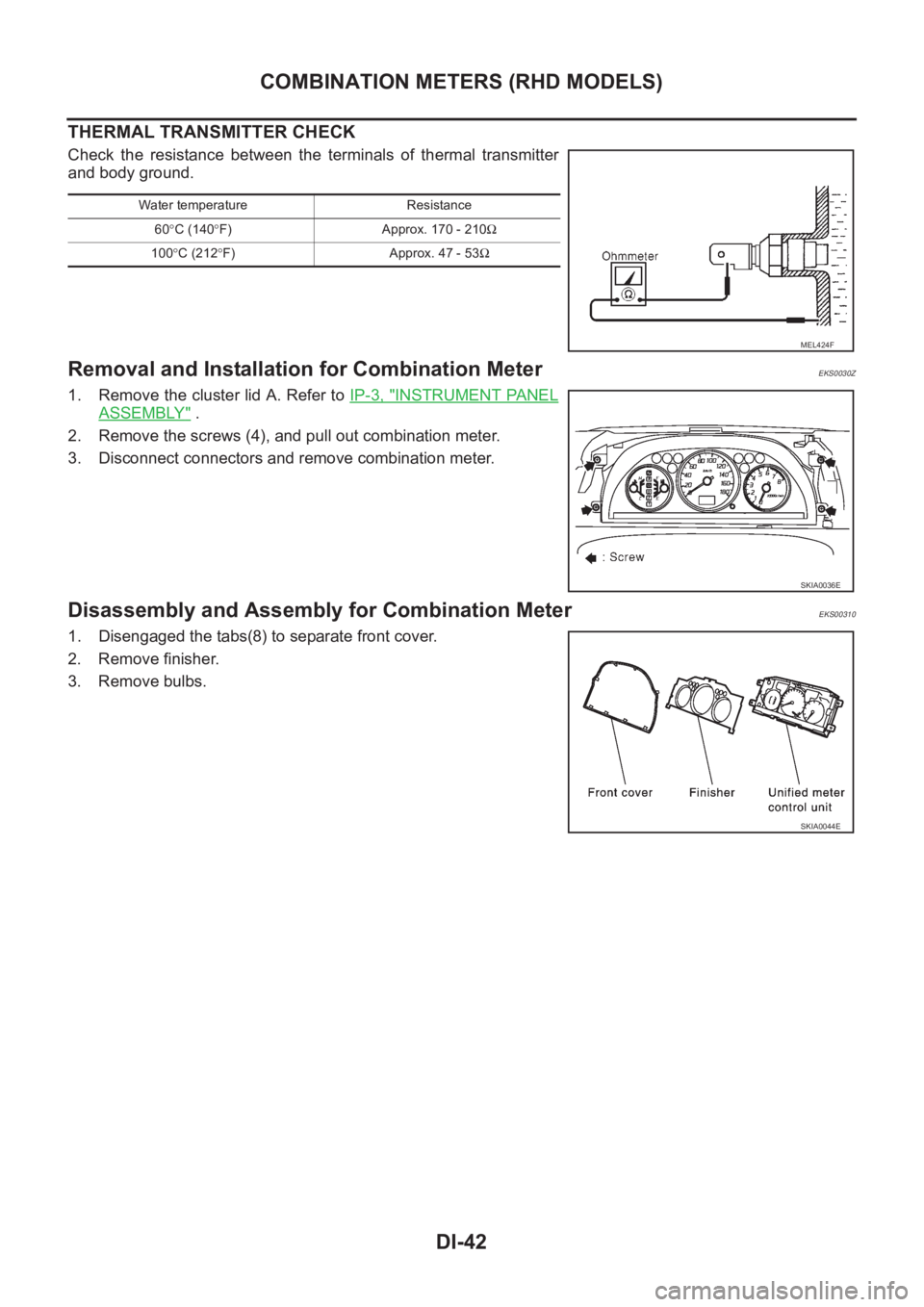
THERMAL TRANSMITTER CHECK
Check the resistance between the terminals of thermal transmitter
and body ground.
Removal and Installation for Combination MeterEKS0030Z
1. Remove the cluster lid A. Refer to IP-3, "INSTRUMENT PANEL
ASSEMBLY" .
2. Remove the screws (4), and pull out combination meter.
3. Disconnect connectors and remove combination meter.
Disassembly and Assembly for Combination MeterEKS00310
1. Disengaged the tabs(8) to separate front cover.
2. Remove finisher.
3. Remove bulbs.
Water temperature Resistance
60°C (140°F) Approx. 170 - 210Ω
100°C (212°F) Approx. 47 - 53Ω
MEL424F
SKIA0036E
SKIA0044E