NISSAN X-TRAIL 2001 Service Repair Manual
Manufacturer: NISSAN, Model Year: 2001, Model line: X-TRAIL, Model: NISSAN X-TRAIL 2001Pages: 3833, PDF Size: 39.49 MB
Page 3621 of 3833
WARNING CHIME
DI-63
C
D
E
F
G
H
I
J
L
MA
B
DI
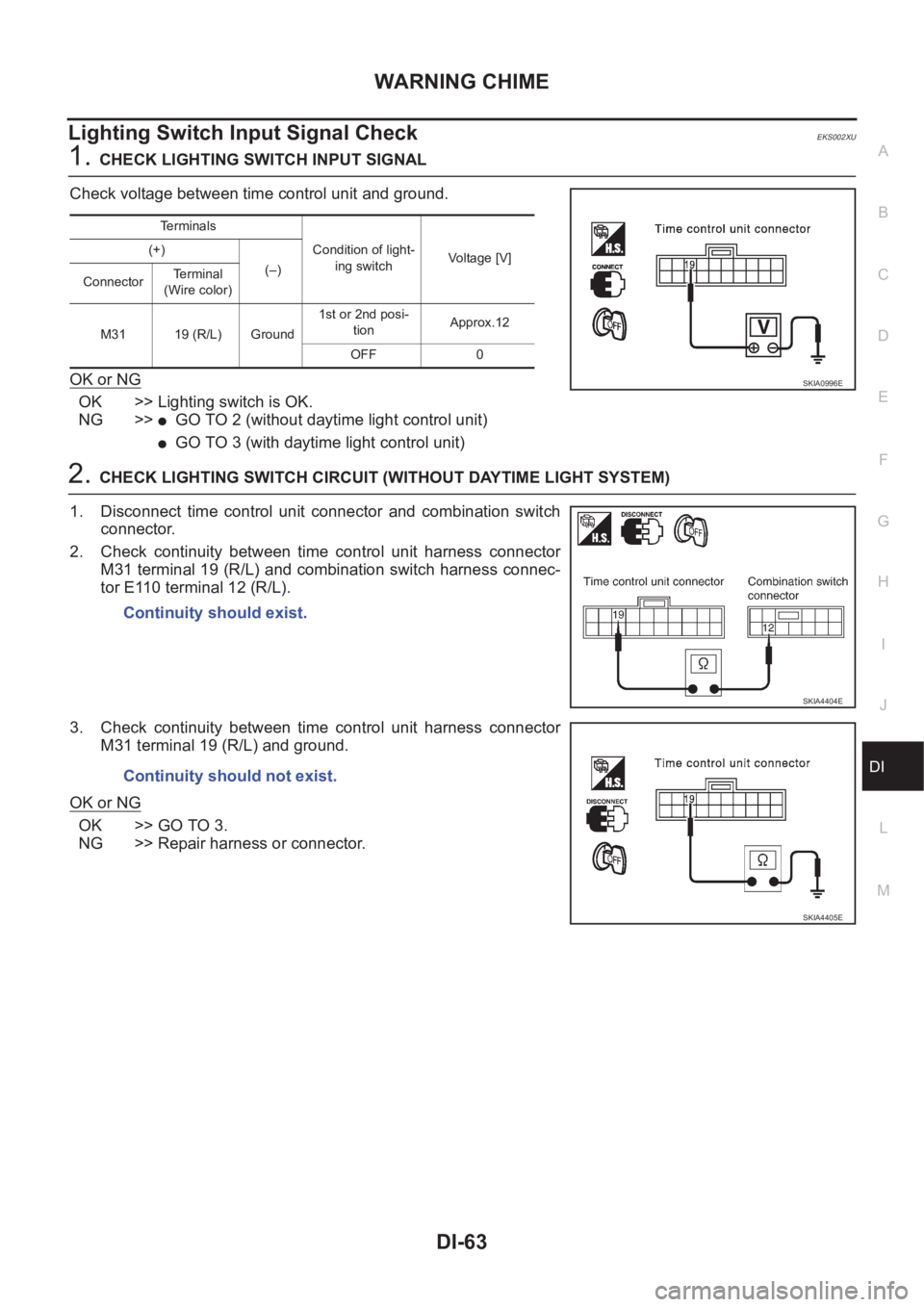
Lighting Switch Input Signal Check EKS002XU
1.CHECK LIGHTING SWITCH INPUT SIGNAL
Check voltage between time control unit and ground.
OK or NG
OK >> Lighting switch is OK.
NG >>
●GO TO 2 (without daytime light control unit)
●GO TO 3 (with daytime light control unit)
2.CHECK LIGHTING SWITCH CIRCUIT (WITHOUT DAYTIME LIGHT SYSTEM)
1. Disconnect time control unit connector and combination switch
connector.
2. Check continuity between time control unit harness connector
M31 terminal 19 (R/L) and combination switch harness connec-
tor E110 terminal 12 (R/L).
3. Check continuity between time control unit harness connector
M31 terminal 19 (R/L) and ground.
OK or NG
OK >> GO TO 3.
NG >> Repair harness or connector.
Te r m i n a l s
Condition of light-
ing switchVoltage [V] (+)
(–)
ConnectorTerminal
(Wire color)
M31 19 (R/L) Ground1st or 2nd posi-
tionApprox.12
OFF 0
SKIA0996E
Continuity should exist.
SKIA4404E
Continuity should not exist.
SKIA4405E
Page 3622 of 3833
DI-64
WARNING CHIME
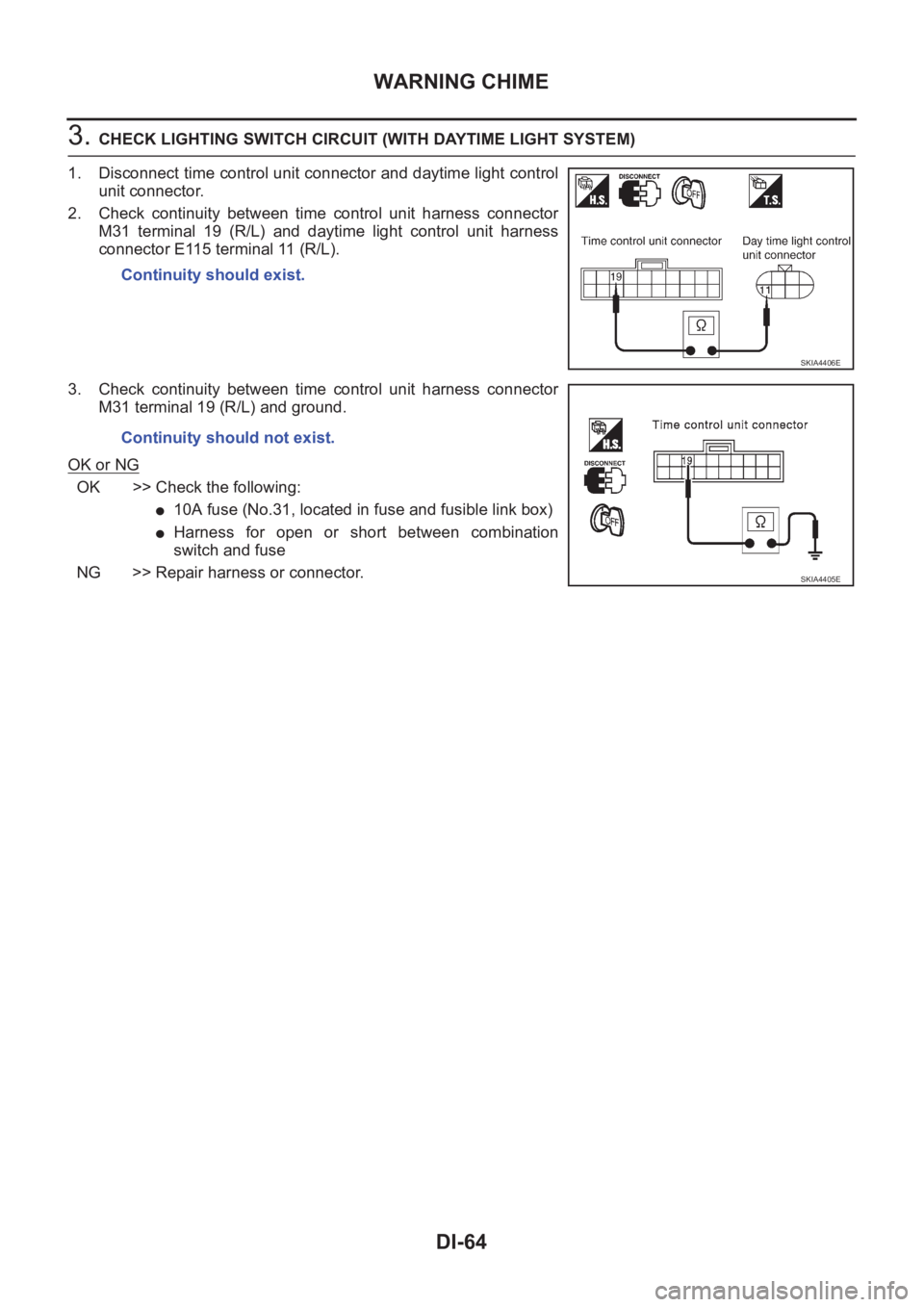
3. CHECK LIGHTING SWITCH CIRCUIT (WITH DAYTIME LIGHT SYSTEM)
1. Disconnect time control unit connector and daytime light control
unit connector.
2. Check continuity between time control unit harness connector
M31 terminal 19 (R/L) and daytime light control unit harness
connector E115 terminal 11 (R/L).
3. Check continuity between time control unit harness connector
M31 terminal 19 (R/L) and ground.
OK or NG
OK >> Check the following:
●10A fuse (No.31, located in fuse and fusible link box)
●Harness for open or short between combination
switch and fuse
NG >> Repair harness or connector.Continuity should exist.
SKIA4406E
Continuity should not exist.
SKIA4405E
Page 3623 of 3833
WARNING CHIME
DI-65
C
D
E
F
G
H
I
J
L
MA
B
DI
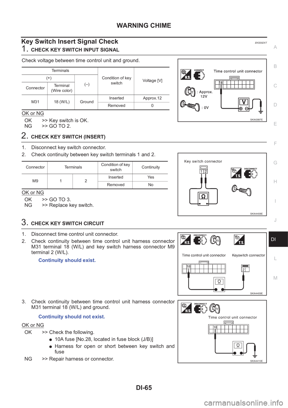
Key Switch Insert Signal Check EKS002XT
1.CHECK KEY SWITCH INPUT SIGNAL
Check voltage between time control unit and ground.
OK or NG
OK >> Key switch is OK.
NG >> GO TO 2.
2.CHECK KEY SWITCH (INSERT)
1. Disconnect key switch connector.
2. Check continuity between key switch terminals 1 and 2.
OK or NG
OK >> GO TO 3.
NG >> Replace key switch.
3.CHECK KEY SWITCH CIRCUIT
1. Disconnect time control unit connector.
2. Check continuity between time control unit harness connector
M31 terminal 18 (W/L) and key switch harness connector M9
terminal 2 (W/L).
3. Check continuity between time control unit harness connector
M31 terminal 18 (W/L) and ground.
OK or NG
OK >> Check the following.
●10A fuse [No.28, located in fuse block (J/B)]
●Harness for open or short between key switch and
fuse
NG >> Repair harness or connector.
Terminals
Condition of key
switchVoltag e [V] (+)
(–)
ConnectorTerminal
(Wire color)
M31 18 (W/L) GroundInserted Approx.12
Removed 0
SKIA0997E
Connector TerminalsCondition of key
switchContinuity
M9 1 2Inserted Yes
Removed No
SKIA4408E
Continuity should exist.
SKIA4409E
Continuity should not exist.
SKIA4410E
Page 3624 of 3833
DI-66
WARNING CHIME
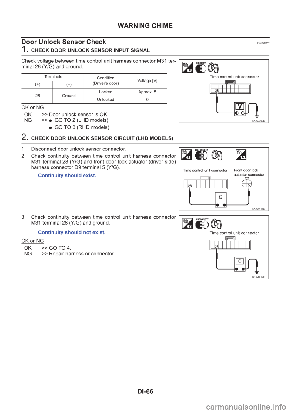
Door Unlock Sensor Check
EKS002YG
1. CHECK DOOR UNLOCK SENSOR INPUT SIGNAL
Check voltage between time control unit harness connector M31 ter-
minal 28 (Y/G) and ground.
OK or NG
OK >> Door unlock sensor is OK.
NG >>
●GO TO 2 (LHD models).
●GO TO 3 (RHD models)
2. CHECK DOOR UNLOCK SENSOR CIRCUIT (LHD MODELS)
1. Disconnect door unlock sensor connector.
2. Check continuity between time control unit harness connector
M31 terminal 28 (Y/G) and front door lock actuator (driver side)
harness connector D9 terminal 5 (Y/G).
3. Check continuity between time control unit harness connector
M31 terminal 28 (Y/G) and ground.
OK or NG
OK >> GO TO 4.
NG >> Repair harness or connector.
Terminals
Condition
(Driver's door)Voltage [V]
(+) (–)
28 GroundLocked Approx. 5
Unlocked 0
SKIA0999E
Continuity should exist.
SKIA4411E
Continuity should not exist.
SKIA4412E
Page 3625 of 3833
WARNING CHIME
DI-67
C
D
E
F
G
H
I
J
L
MA
B
DI
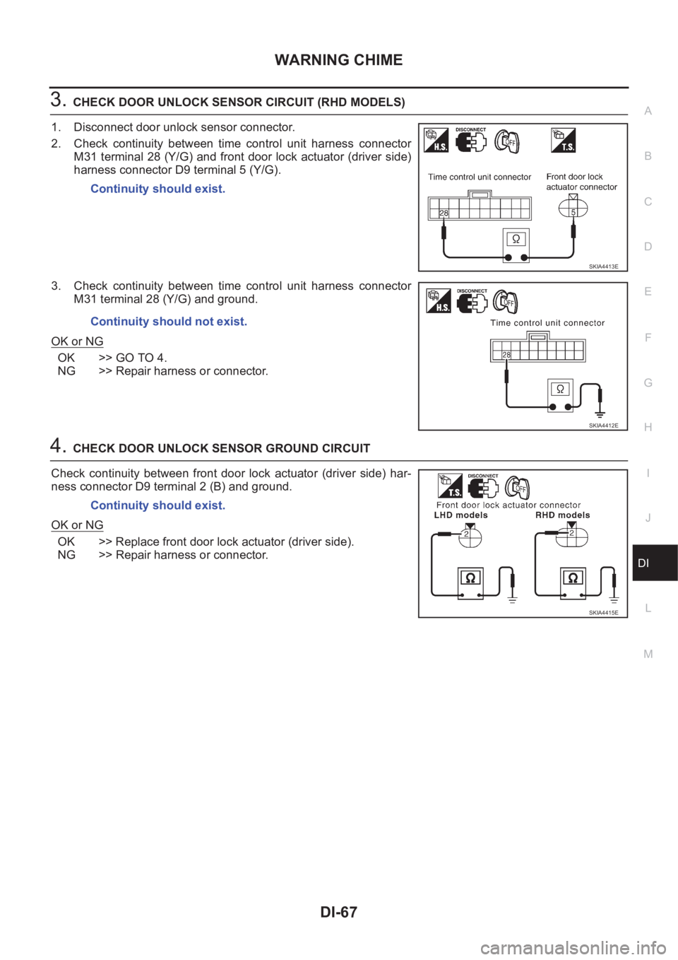
3.CHECK DOOR UNLOCK SENSOR CIRCUIT (RHD MODELS)
1. Disconnect door unlock sensor connector.
2. Check continuity between time control unit harness connector
M31 terminal 28 (Y/G) and front door lock actuator (driver side)
harness connector D9 terminal 5 (Y/G).
3. Check continuity between time control unit harness connector
M31 terminal 28 (Y/G) and ground.
OK or NG
OK >> GO TO 4.
NG >> Repair harness or connector.
4.CHECK DOOR UNLOCK SENSOR GROUND CIRCUIT
Check continuity between front door lock actuator (driver side) har-
ness connector D9 terminal 2 (B) and ground.
OK or NG
OK >> Replace front door lock actuator (driver side).
NG >> Repair harness or connector.Continuity should exist.
SKIA4413E
Continuity should not exist.
SKIA4412E
Continuity should exist.
SKIA4415E
Page 3626 of 3833
DI-68
WARNING CHIME
Front Door Switch (driver side) Check
EKS002YH
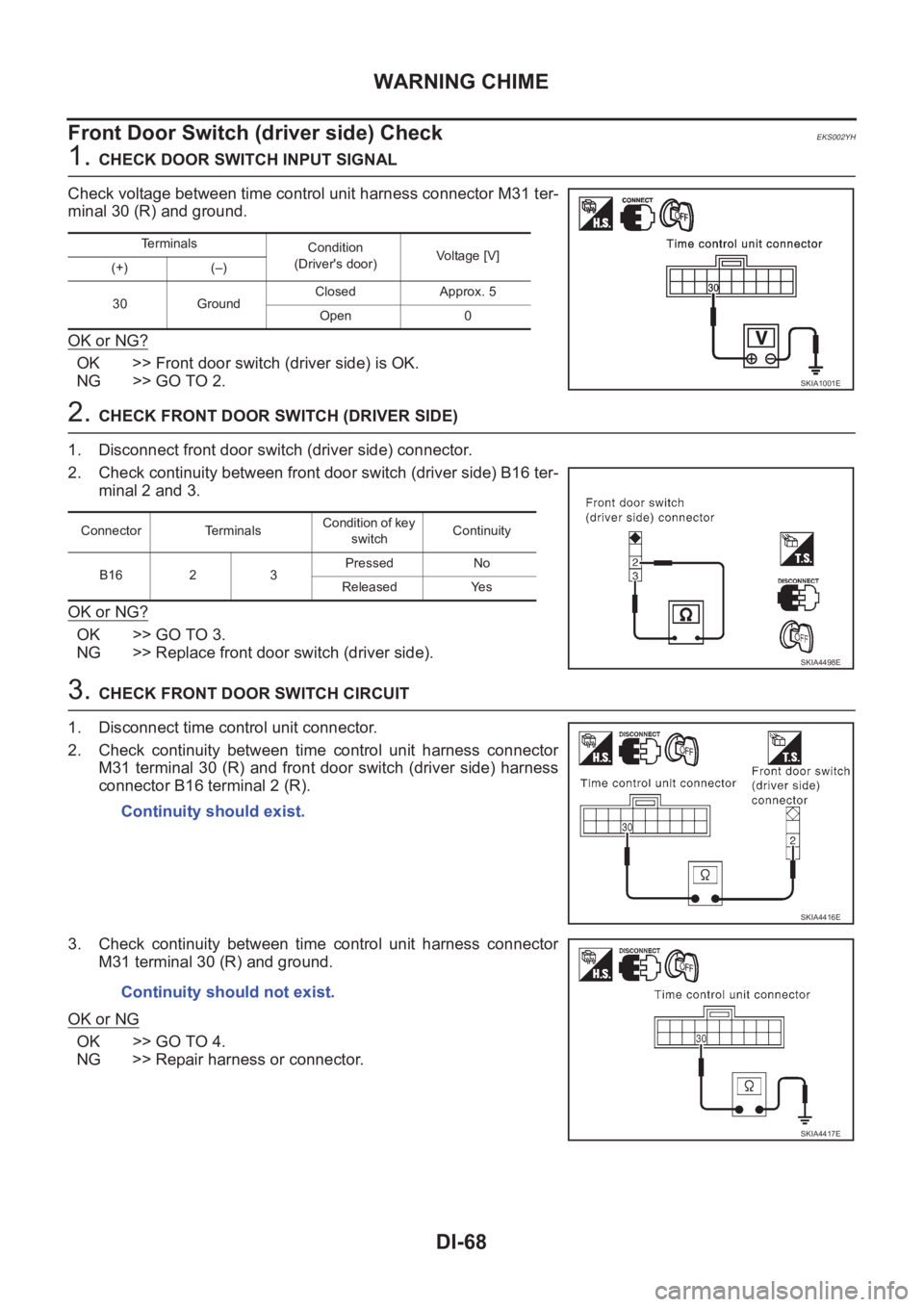
1. CHECK DOOR SWITCH INPUT SIGNAL
Check voltage between time control unit harness connector M31 ter-
minal 30 (R) and ground.
OK or NG?
OK >> Front door switch (driver side) is OK.
NG >> GO TO 2.
2. CHECK FRONT DOOR SWITCH (DRIVER SIDE)
1. Disconnect front door switch (driver side) connector.
2. Check continuity between front door switch (driver side) B16 ter-
minal 2 and 3.
OK or NG?
OK >> GO TO 3.
NG >> Replace front door switch (driver side).
3. CHECK FRONT DOOR SWITCH CIRCUIT
1. Disconnect time control unit connector.
2. Check continuity between time control unit harness connector
M31 terminal 30 (R) and front door switch (driver side) harness
connector B16 terminal 2 (R).
3. Check continuity between time control unit harness connector
M31 terminal 30 (R) and ground.
OK or NG
OK >> GO TO 4.
NG >> Repair harness or connector.
Terminals
Condition
(Driver's door)Voltage [V]
(+) (–)
30 GroundClosed Approx. 5
Open 0
SKIA1001E
Connector TerminalsCondition of key
switchContinuity
B16 2 3Pressed No
Released Yes
SKIA4498E
Continuity should exist.
SKIA4416E
Continuity should not exist.
SKIA4417E
Page 3627 of 3833
WARNING CHIME
DI-69
C
D
E
F
G
H
I
J
L
MA
B
DI
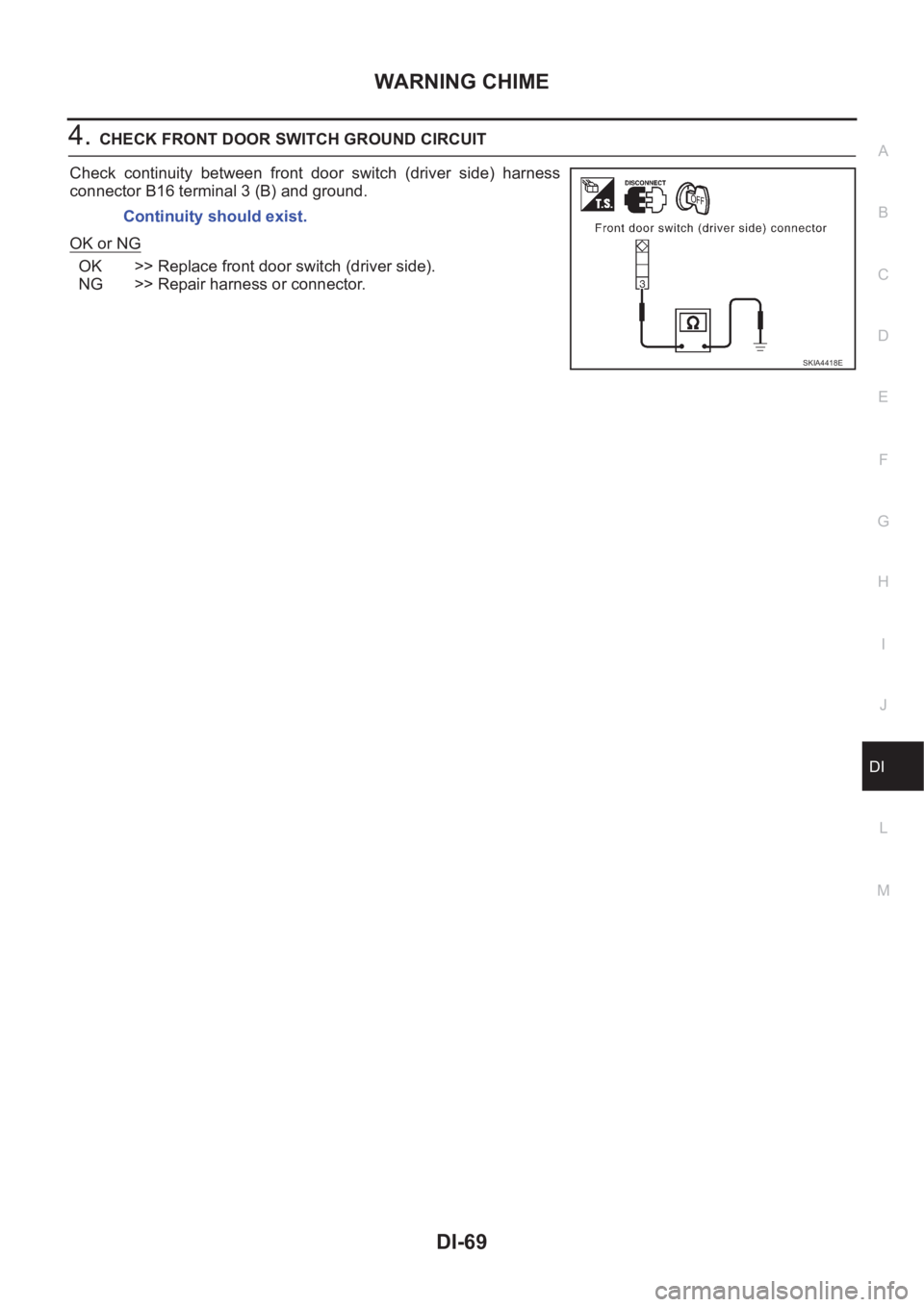
4.CHECK FRONT DOOR SWITCH GROUND CIRCUIT
Check continuity between front door switch (driver side) harness
connector B16 terminal 3 (B) and ground.
OK or NG
OK >> Replace front door switch (driver side).
NG >> Repair harness or connector.Continuity should exist.
SKIA4418E
Page 3628 of 3833
DI-70
CLOCK
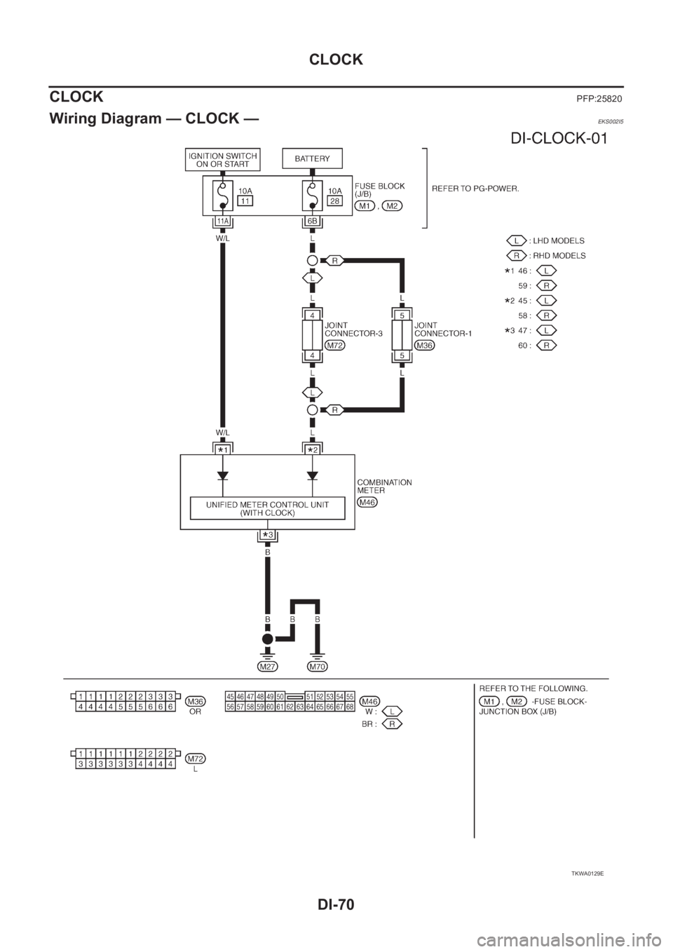
CLOCK
PFP:25820
Wiring Diagram — CLOCK —EKS002I5
TKWA0129E
Page 3629 of 3833
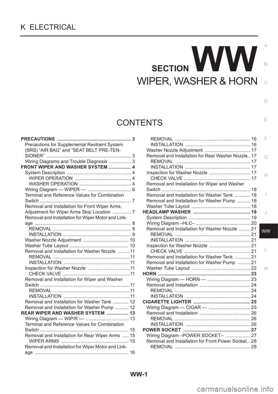
WW-1
WIPER, WASHER & HORN
K ELECTRICAL
CONTENTS
C
D
E
F
G
H
I
J
L
M
SECTION
A
B
WW
WIPER, WASHER & HORN
PRECAUTIONS .......................................................... 3
Precautions for Supplemental Restraint System
(SRS) “AIR BAG” and “SEAT BELT PRE-TEN-
SIONER” .................................................................. 3
Wiring Diagrams and Trouble Diagnosis .................. 3
FRONT WIPER AND WASHER SYSTEM .................. 4
System Description .................................................. 4
WIPER OPERATION ............................................ 4
WASHER OPERATION ......................................... 4
Wiring Diagram — WIPER — .................................. 6
Terminal and Reference Values for Combination
Switch ....................................................................... 7
Removal and Installation for Front Wiper Arms,
Adjustment for Wiper Arms Stop Location ............... 7
Removal and Installation for Wiper Motor and Link-
age ........................................................................... 8
REMOVAL ............................................................. 9
INSTALLATION ..................................................... 9
Washer Nozzle Adjustment .................................... 10
Washer Tube Layout .............................................. 10
Removal and Installation for Washer Nozzle .......... 11
REMOVAL ............................................................ 11
INSTALLATION .................................................... 11
Inspection for Washer Nozzle ................................. 11
CHECK VALVE .................................................... 11
Removal and Installation for Wiper and Washer
Switch ...................................................................... 11
REMOVAL ............................................................ 11
INSTALLATION .................................................... 11
Removal and Installation for Washer Tank ............. 12
Removal and Installation for Washer Pump ........... 12
REAR WIPER AND WASHER SYSTEM .................. 13
Wiring Diagram — WIP/R — .................................. 13
Terminal and Reference Values for Combination
Switch ..................................................................... 15
Removal and Installation for Rear Wiper Arms ...... 15
WIPER ARMS ..................................................... 15
Removal and Installation for Wiper Motor and Link-
age ......................................................................... 16REMOVAL ........................................................... 16
INSTALLATION ................................................... 16
Washer Nozzle Adjustment .................................... 17
Removal and Installation for Rear Washer Nozzle ... 17
REMOVAL ........................................................... 17
INSTALLATION ................................................... 17
Inspection for Washer Nozzle ................................. 17
CHECK VALVE .................................................... 17
Removal and Installation for Wiper and Washer
Switch ..................................................................... 18
Removal and Installation for Washer Tank ............. 18
Removal and Installation for Washer Pump ........... 18
Washer Tube Layout .............................................. 18
HEADLAMP WASHER ............................................. 19
System Description ................................................. 19
Wiring Diagram –HLC– ........................................... 20
Removal and Installation for Washer Nozzle .......... 21
REMOVAL ........................................................... 21
INSTALLATION ................................................... 21
Inspection for Washer Nozzle ................................. 21
CHECK VALVE .................................................... 21
Removal and Installation for Washer Tank ............. 21
Removal and Installation for Washer Pump ........... 21
Washer Tube Layout .............................................. 22
HORN ........................................................................ 23
Wiring Diagram — HORN — .................................. 23
Removal and Installation ........................................ 24
REMOVAL ........................................................... 24
INSTALLATION ................................................... 24
CIGARETTE LIGHTER ............................................. 25
Wiring Diagram — CIGAR — ................................. 25
Removal and Installation ........................................ 26
REMOVAL ........................................................... 26
INSTALLATION ................................................... 26
POWER SOCKET ..................................................... 27
Wiring Diagram –POWER SOCKET– .................... 27
Removal and Installation for Front Power Socket ... 28
REMOVAL ........................................................... 28
Page 3630 of 3833
WW-2
INSTALLATION .................................................... 28
Removal and Installation for Rear Power Socket ... 28
REMOVAL ........................................................... 28
INSTALLATION .................................................... 28