NISSAN X-TRAIL 2001 Service Repair Manual
X-TRAIL 2001
NISSAN
NISSAN
https://www.carmanualsonline.info/img/5/57405/w960_57405-0.png
NISSAN X-TRAIL 2001 Service Repair Manual
Trending: tire pressure, instrument cluster, fuel, fuses, key battery, At-118, power steering pump
Page 3651 of 3833
HORN
WW-23
C
D
E
F
G
H
I
J
L
MA
B
WW
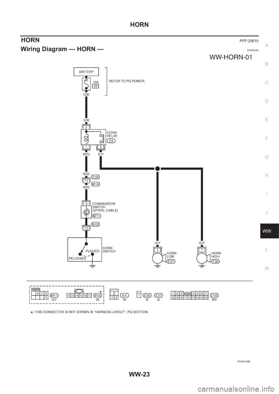
HORNPFP:25610
Wiring Diagram — HORN —EKS0033A
TKWA0108E
Page 3652 of 3833
WW-24
HORN
Removal and Installation
EKS0033B
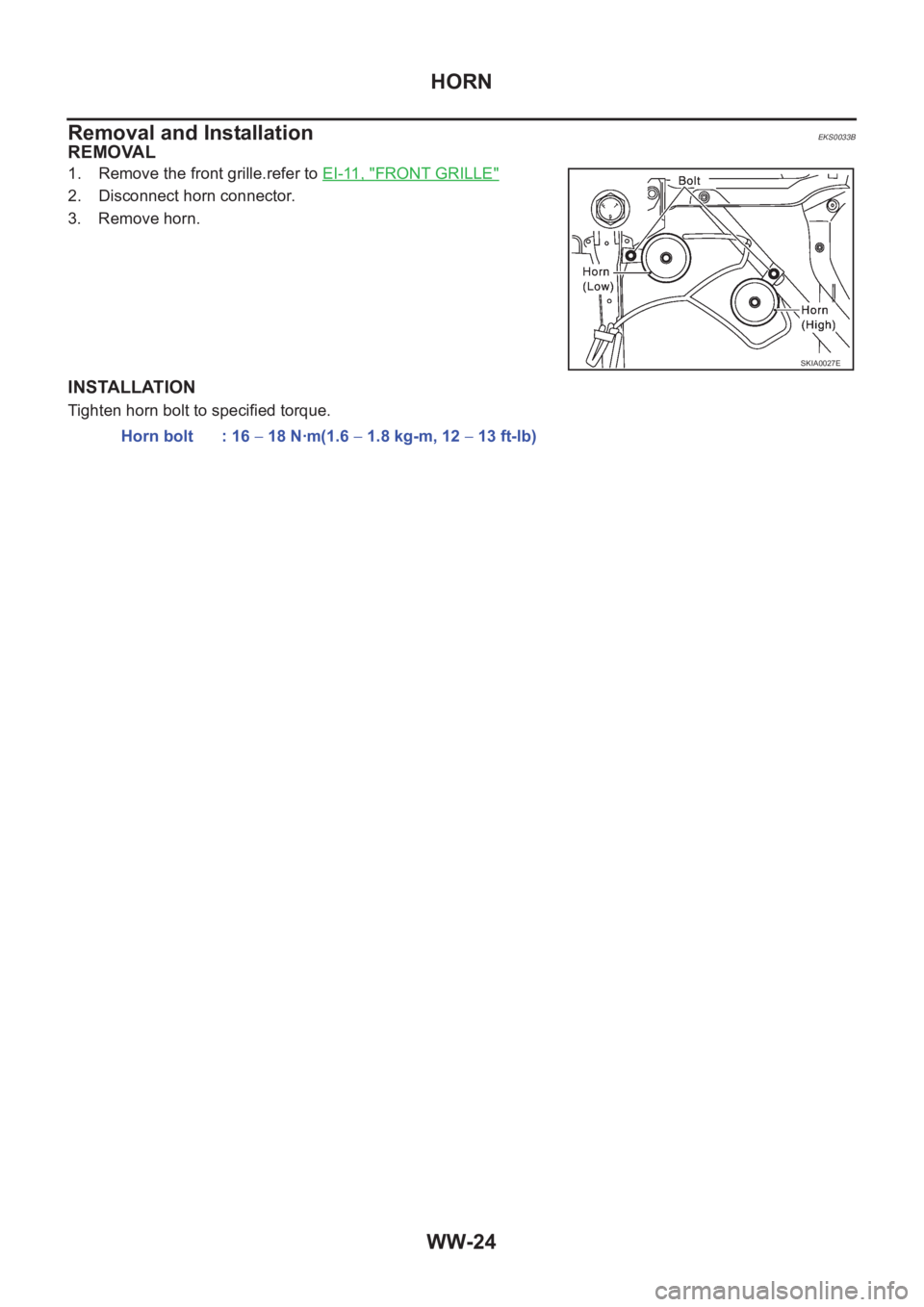
REMOVAL
1. Remove the front grille.refer to EI-11, "FRONT GRILLE"
2. Disconnect horn connector.
3. Remove horn.
INSTALLATION
Tighten horn bolt to specified torque.
SKIA0027E
Horn bolt : 16 − 18 N·m(1.6 − 1.8 kg-m, 12 − 13 ft-lb)
Page 3653 of 3833
CIGARETTE LIGHTER
WW-25
C
D
E
F
G
H
I
J
L
MA
B
WW
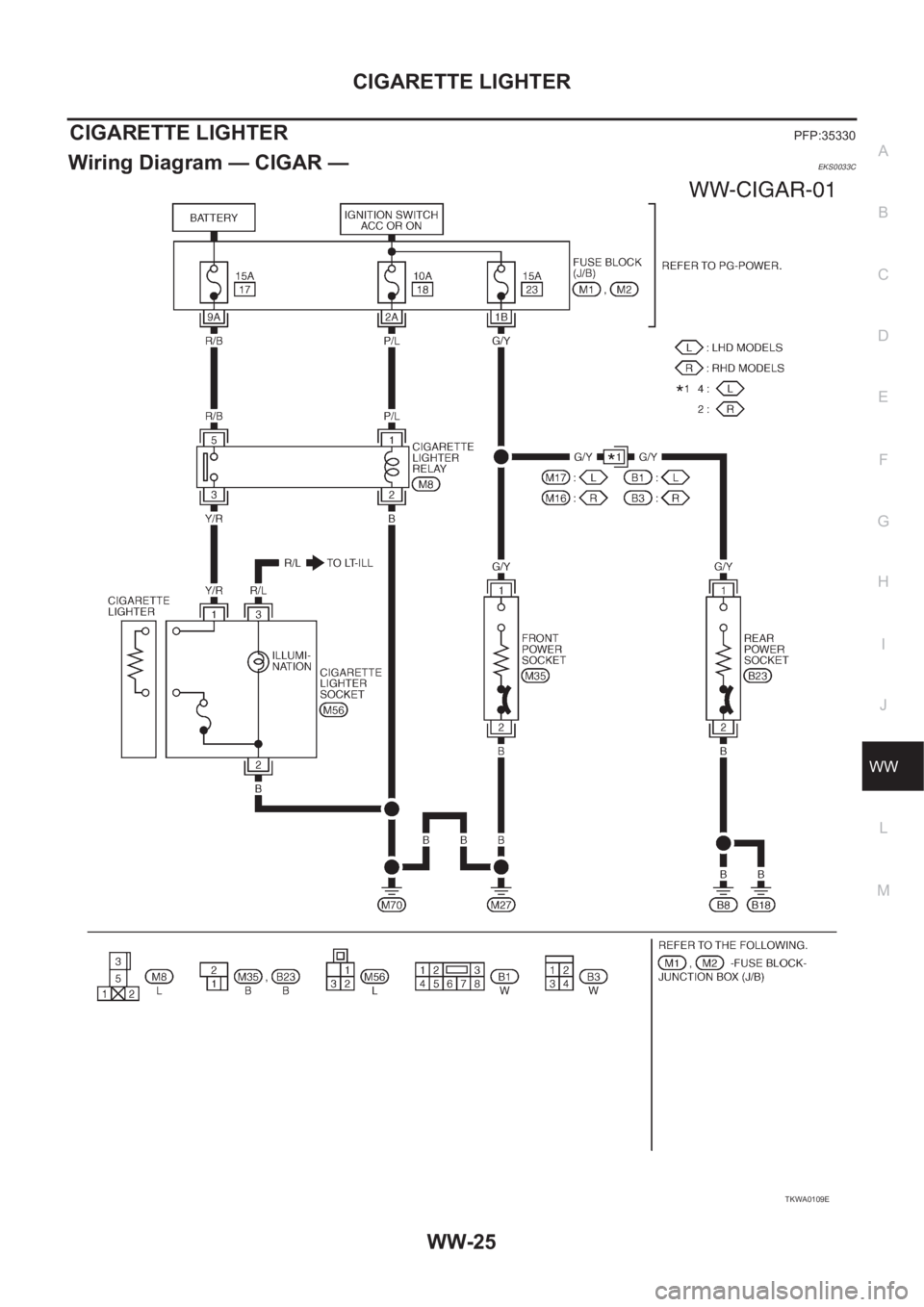
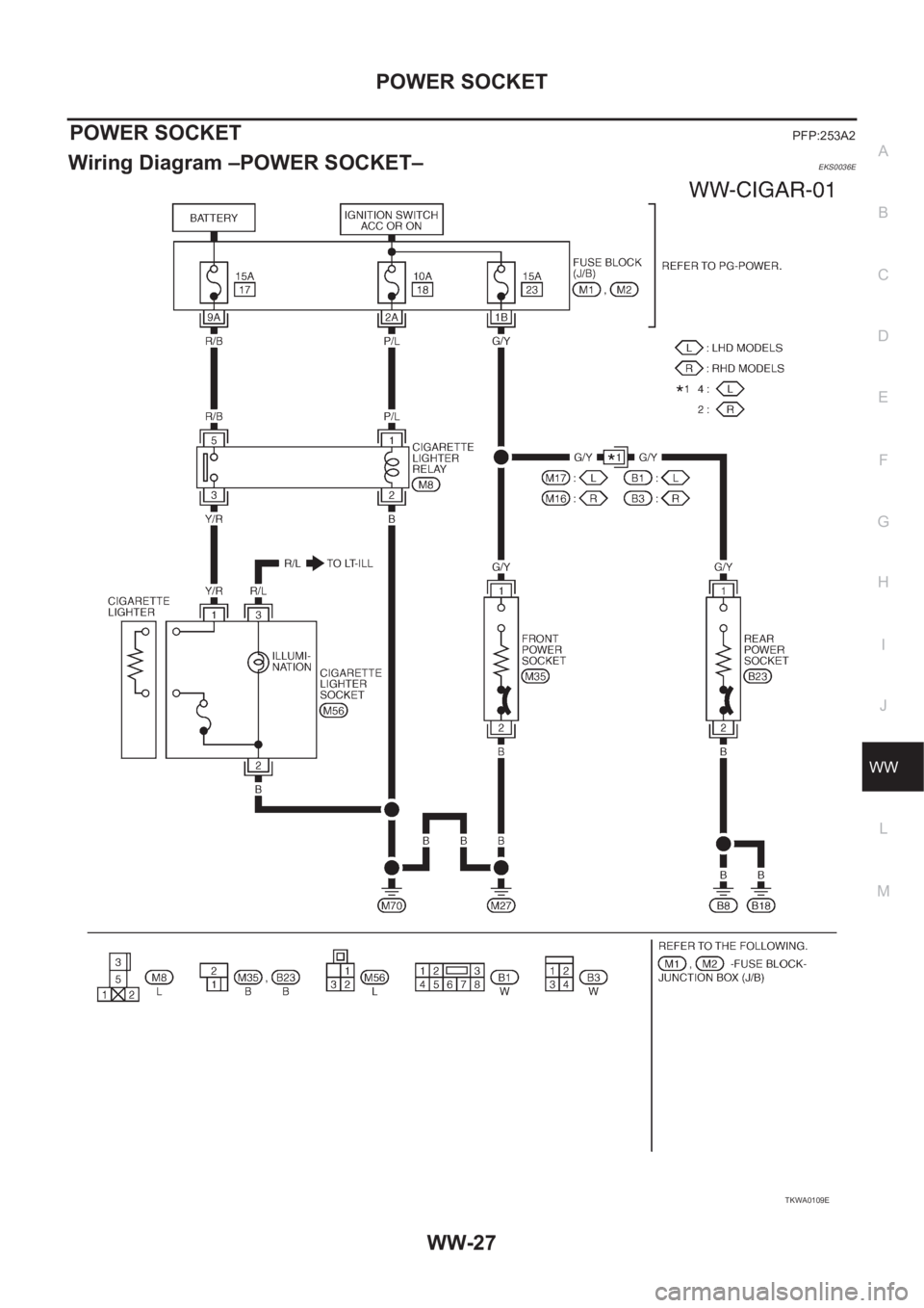
CIGARETTE LIGHTERPFP:35330
Wiring Diagram — CIGAR —EKS0033C
TKWA0109E
Page 3654 of 3833
WW-26
CIGARETTE LIGHTER
Removal and Installation
EKS0033D
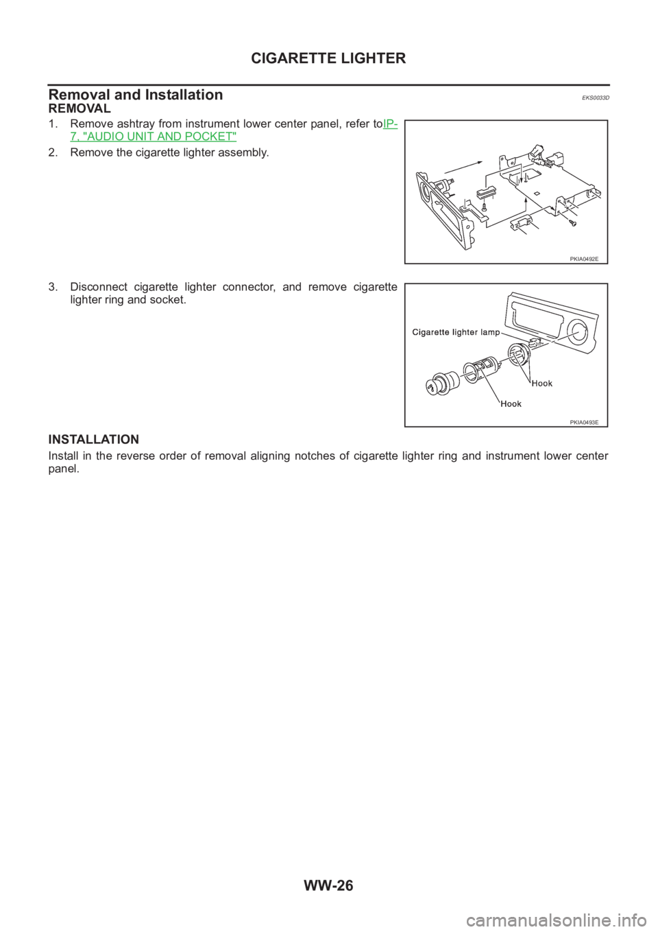
REMOVAL
1. Remove ashtray from instrument lower center panel, refer toIP-
7, "AUDIO UNIT AND POCKET"
2. Remove the cigarette lighter assembly.
3. Disconnect cigarette lighter connector, and remove cigarette
lighter ring and socket.
INSTALLATION
Install in the reverse order of removal aligning notches of cigarette lighter ring and instrument lower center
panel.
PKIA0492E
PKIA0493E
Page 3655 of 3833
POWER SOCKET
WW-27
C
D
E
F
G
H
I
J
L
MA
B
WW
POWER SOCKETPFP:253A2
Wiring Diagram –POWER SOCKET–EKS0036E
TKWA0109E
Page 3656 of 3833
WW-28
POWER SOCKET
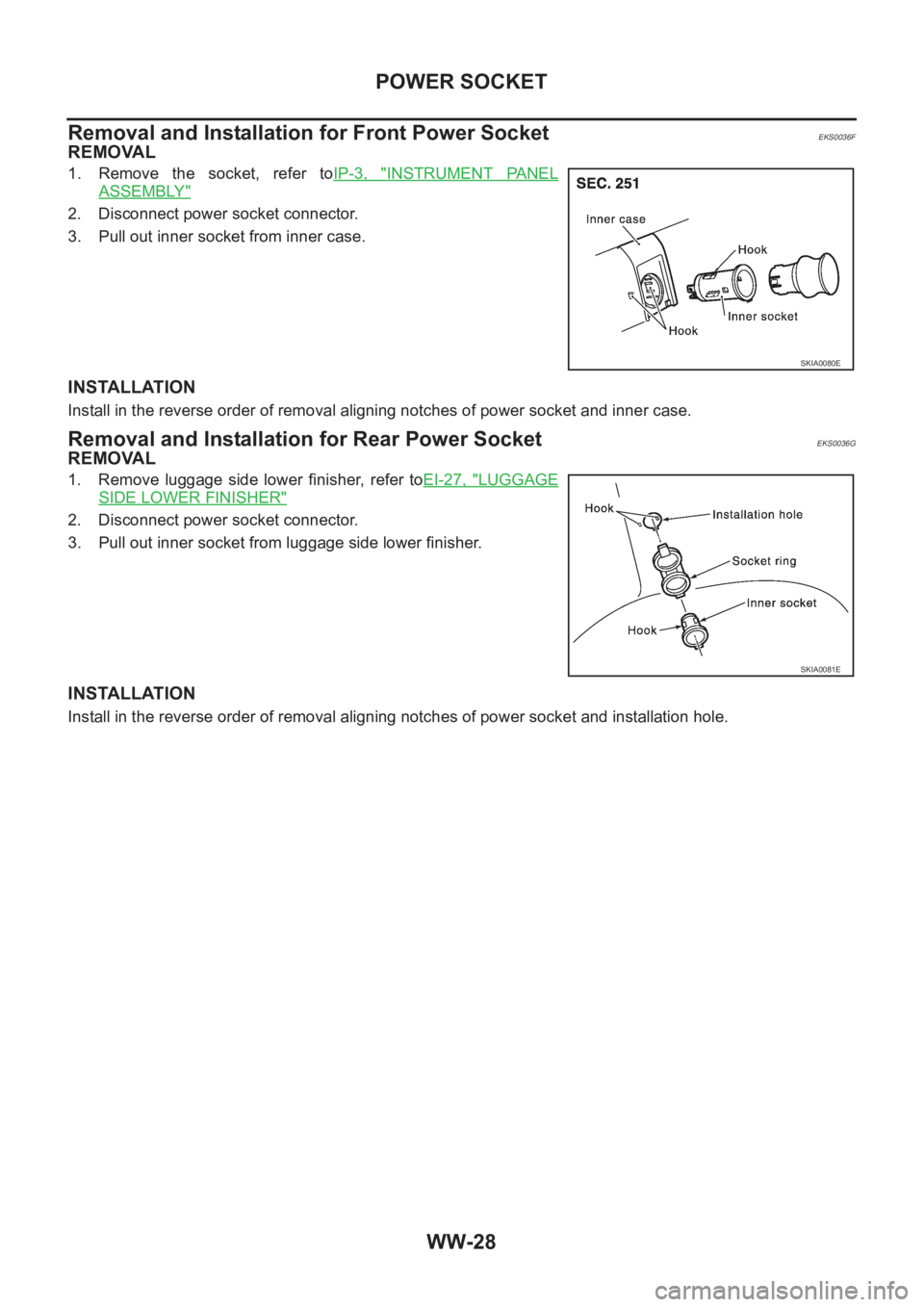
Removal and Installation for Front Power Socket
EKS0036F
REMOVAL
1. Remove the socket, refer toIP-3, "INSTRUMENT PANEL
ASSEMBLY"
2. Disconnect power socket connector.
3. Pull out inner socket from inner case.
INSTALLATION
Install in the reverse order of removal aligning notches of power socket and inner case.
Removal and Installation for Rear Power SocketEKS0036G
REMOVAL
1. Remove luggage side lower finisher, refer toEI-27, "LUGGAGE
SIDE LOWER FINISHER"
2. Disconnect power socket connector.
3. Pull out inner socket from luggage side lower finisher.
INSTALLATION
Install in the reverse order of removal aligning notches of power socket and installation hole.
SKIA0080E
SKIA0081E
Page 3657 of 3833
BCS-1
BODY CONTROL SYSTEM
K ELECTRICAL
CONTENTS
C
D
E
F
G
H
I
J
L
M
SECTION
A
B
BCS
BODY CONTROL SYSTEM
PRECAUTIONS .......................................................... 2
Precautions for Supplemental Restraint System
(SRS) “AIR BAG” and “SEAT BELT PRE-TEN-
SIONER” .................................................................. 2
Wiring Diagrams and Trouble Diagnosis .................. 2
TIME CONTROL UNIT ............................................... 3Description ................................................................ 3
OUTLINE ............................................................... 3
INPUT/OUTPUT .................................................... 3
Schematic ................................................................. 4
Time Control Unit Inspection Table ........................... 5
Page 3658 of 3833
BCS-2
PRECAUTIONS
PRECAUTIONS
PFP:00011
Precautions for Supplemental Restraint System (SRS) “AIR BAG” and “SEAT
BELT PRE-TENSIONER”
EKS0079N
The Supplemental Restraint System such as “AIR BAG” and “SEAT BELT PRE-TENSIONER”, used along
with a front seat belt, helps to reduce the risk or severity of injury to the driver and front passenger for certain
types of collision. Information necessary to service the system safely is included in the SRS and SB section of
this Service Manual.
WARNING:
●To avoid rendering the SRS inoperative, which could increase the risk of personal injury or death
in the event of a collision which would result in air bag inflation, all maintenance must be per-
formed by an authorized NISSAN/INFINITI dealer.
●Improper maintenance, including incorrect removal and installation of the SRS, can lead to per-
sonal injury caused by unintentional activation of the system. For removal of Spiral Cable and Air
Bag Module, see the SRS section.
●Do not use electrical test equipment on any circuit related to the SRS unless instructed to in this
Service Manual. SRS wiring harnesses can be identified by yellow and/or orange harness connec-
tors.
Wiring Diagrams and Trouble Diagnosis EKS0079O
When you read wiring diagrams, refer to the followings:
●Refer to GI-13, "How to Read Wiring Diagrams" in GI section
●Refer to PG-2, "POWER SUPPLY ROUTING" for power distribution circuit in PG section
When you perform trouble diagnosis, refer to the followings:
●Refer to GI-10, "HOW TO FOLLOW TEST GROUPS IN TROUBLE DIAGNOSES" in PG section
●Refer to GI-23, "How to Perform Efficient Diagnosis for an Electrical Incident" in PG section
Page 3659 of 3833
TIME CONTROL UNIT
BCS-3
C
D
E
F
G
H
I
J
L
MA
B
BCS
TIME CONTROL UNITPFP:28491
DescriptionEKS002ZU
OUTLINE
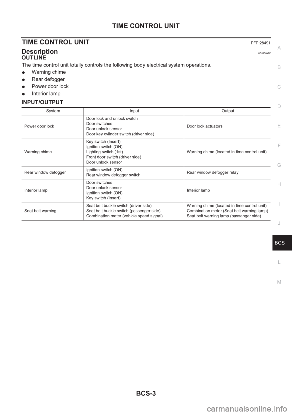
The time control unit totally controls the following body electrical system operations.
●Warning chime
●Rear defogger
●Power door lock
●Interior lamp
INPUT/OUTPUT
System Input Output
Power door lockDoor lock and unlock switch
Door switches
Door unlock sensor
Door key cylinder switch (driver side)Door lock actuators
Warning chimeKey switch (Insert)
Ignition switch (ON)
Lighting switch (1st)
Front door switch (driver side)
Door unlock sensorWarning chime (located in time control unit)
Rear window defoggerIgnition switch (ON)
Rear window defogger switchRear window defogger relay
Interior lampDoor switches
Door unlock sensor
Ignition switch (ON)
Key switch (Insert)Interior lamp
Seat belt warningSeat belt buckle switch (driver side)
Seat belt buckle switch (passenger side)
Combination meter (vehicle speed signal)Warning chime (located in time control unit)
Combination meter (Seat belt warning lamp)
Seat belt warning lamp (passenger side)
Page 3660 of 3833
BCS-4
TIME CONTROL UNIT
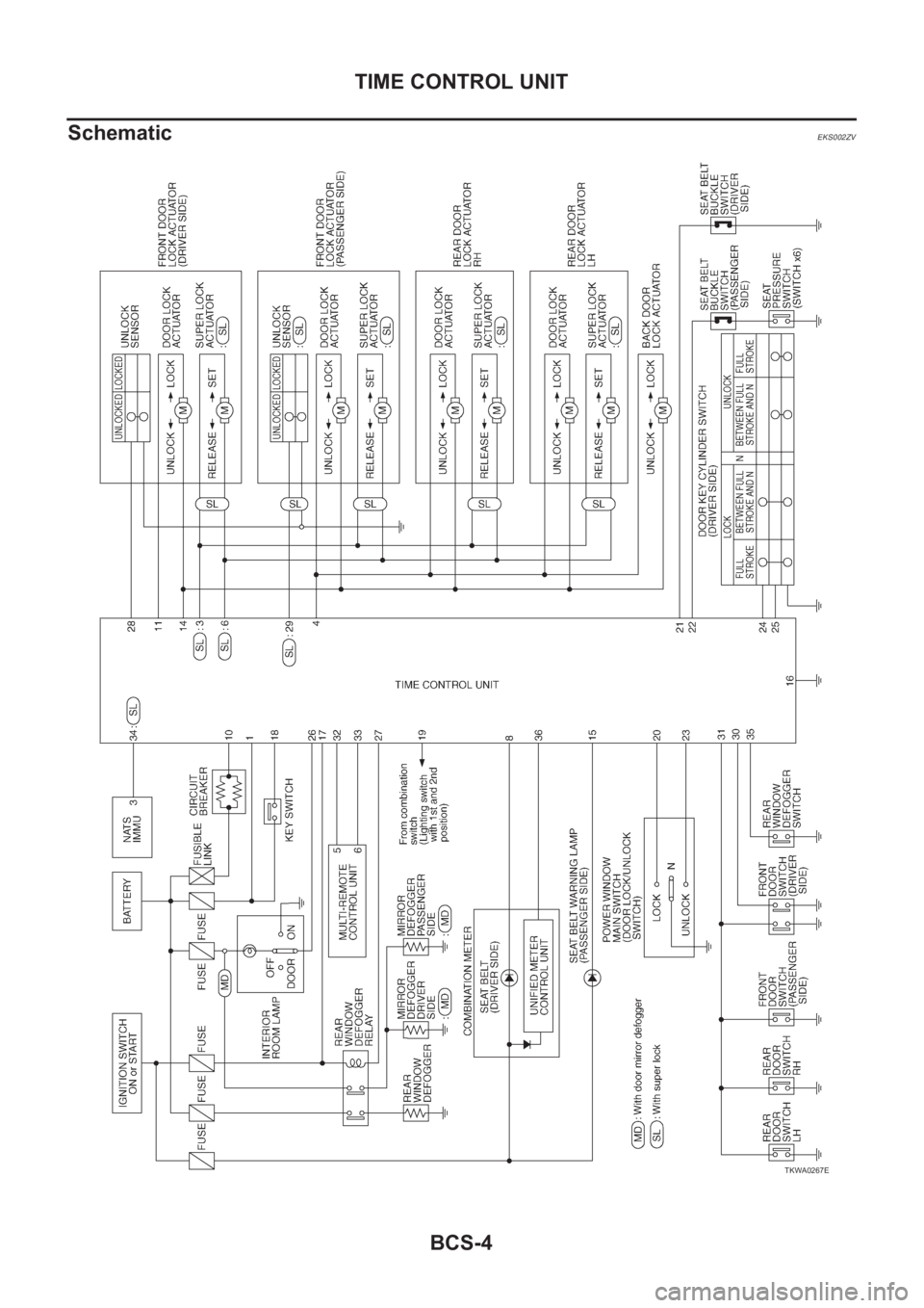
Schematic
EKS002ZV
TKWA0267E
Trending: oil filter, automatic transmission, oil, tailgate, electrical cigarette lighter, ATC-2, oil capacity
