NISSAN X-TRAIL 2001 Service Repair Manual
Manufacturer: NISSAN, Model Year: 2001, Model line: X-TRAIL, Model: NISSAN X-TRAIL 2001Pages: 3833, PDF Size: 39.49 MB
Page 3701 of 3833
AUDIO
AV-13
C
D
E
F
G
H
I
J
L
MA
B
AV
InspectionEKS002F6
AUDIO UNIT
All voltage inspections are made with:
●Ignition switch ON or ACC
●Audio unit ON
●Audio unit connected (If audio unit is removed for inspection, supply a ground to the case using a jumper
wire.)
ANTENNA
Using a jumper wire, clip an auxiliary ground between antenna and body.
●If reception improves, check antenna ground (at body surface).
●If reception does not improve, check main feeder cable for short circuit or open circuit.
Removal and Installation of Audio UnitEKS002PU
1. Remove instrument cluster lid “C”.
● Refer to IP-7, "CLUSTER LID C" in “Instrument Panel (IP)” section.
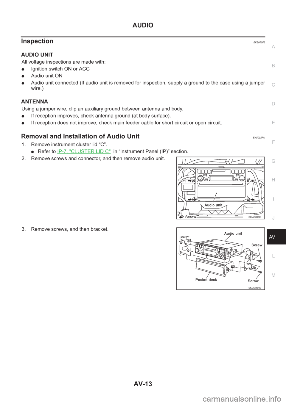
2. Remove screws and connector, and then remove audio unit.
3. Remove screws, and then bracket.
SKIA0890E
SKIA0891E
Page 3702 of 3833
AV-14
AUDIO
Locking CD auto-changer mechanism
EKS002GM
CAUTION:
●Prior to removing a malfunctioning CD auto-changer unit that will be shipped for repair, the
changer mechanism MUST BE LOCKED to prevent the mechanism from being damaged during
shipping.
●If a CD is jammed or unable to be removed from the unit, do NOT lock the changer mechanism. If
the unit is to be shipped for repair, carefully package the unit to prevent vibration and shock.
DAMPER LOCK PROCEDURE
1. Eject and remove any CDs from the CD auto-changer unit.
2. Turn ignition switch OFF. Wait until CD auto-changer unit display is off and mechanism stops moving
(mechanism sound stops).
3. Press any one of the disc selection buttons once. When a display shows on the CD auto-changer unit,
press the same disc selection button again within 5 seconds.
●The changer mechanism will lock itself within 10 seconds.
4. After mechanism stops moving (mechanism sound stops), disconnect negative battery terminal.
NOTE:
After installing a new or remanufactured CD auto-changer unit, switching the CD auto-changer unit ON will
automatically unlock the mechanism. A special unlocking procedure is not required.
Removal and Installation of CD Auto-ChangerEKS002UW
1. Perform damper lock. Refer to AV-14, "DAMPER LOCK PROCEDURE" .
2. Remove cluster lid finishers (left and right).
●Refer to IP-7, "CLUSTER LID FINISHER" in “Instrument Panel (IP)” section.
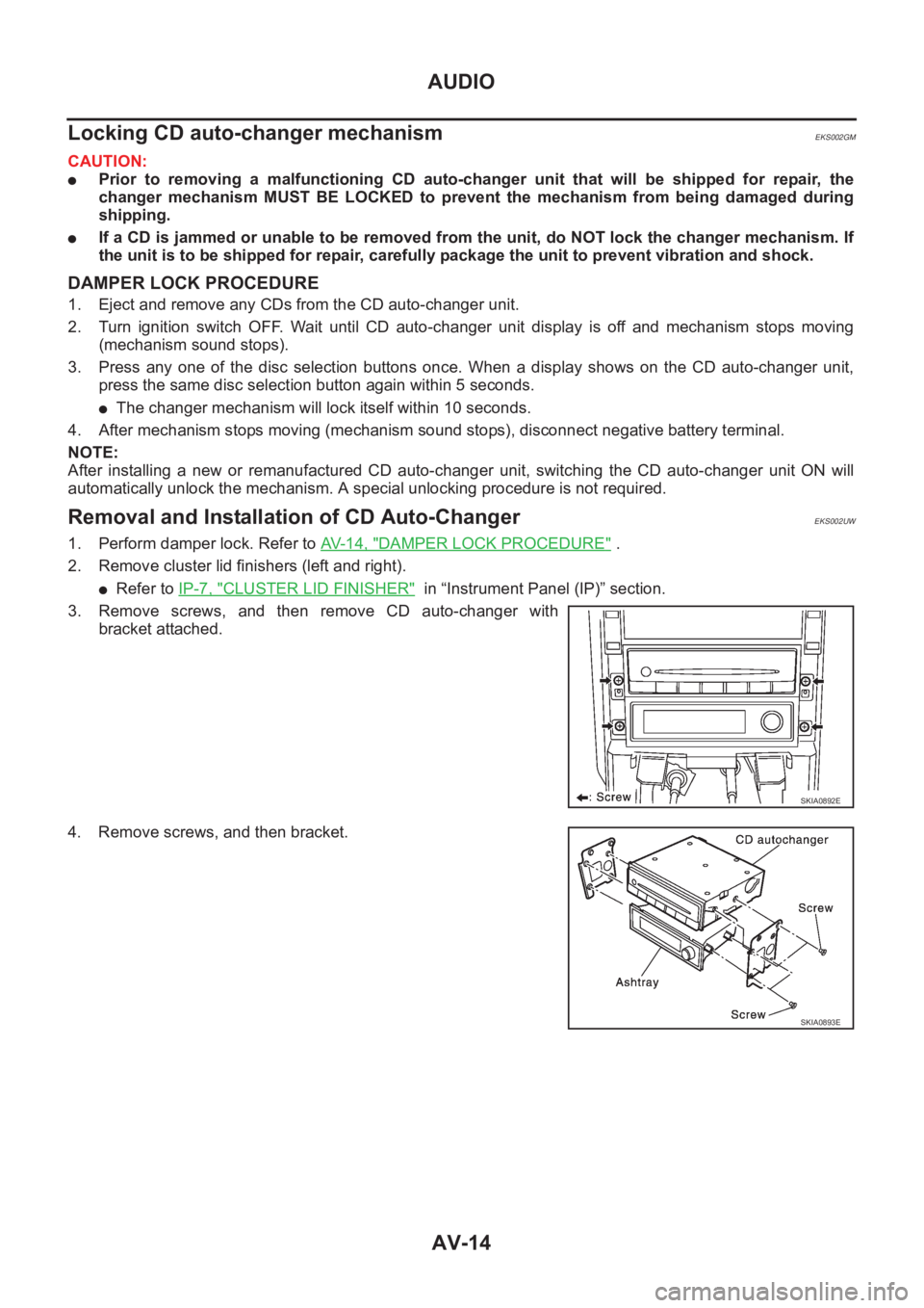
3. Remove screws, and then remove CD auto-changer with
bracket attached.
4. Remove screws, and then bracket.
SKIA0892E
SKIA0893E
Page 3703 of 3833
AUDIO
AV-15
C
D
E
F
G
H
I
J
L
MA
B
AV
Removal and Installation of SpeakersEKS002PV
1. Remove door finisher.
●Refer to EI-23, "DOOR FINISHER" in “Exterior/Interior (EI)”
section.
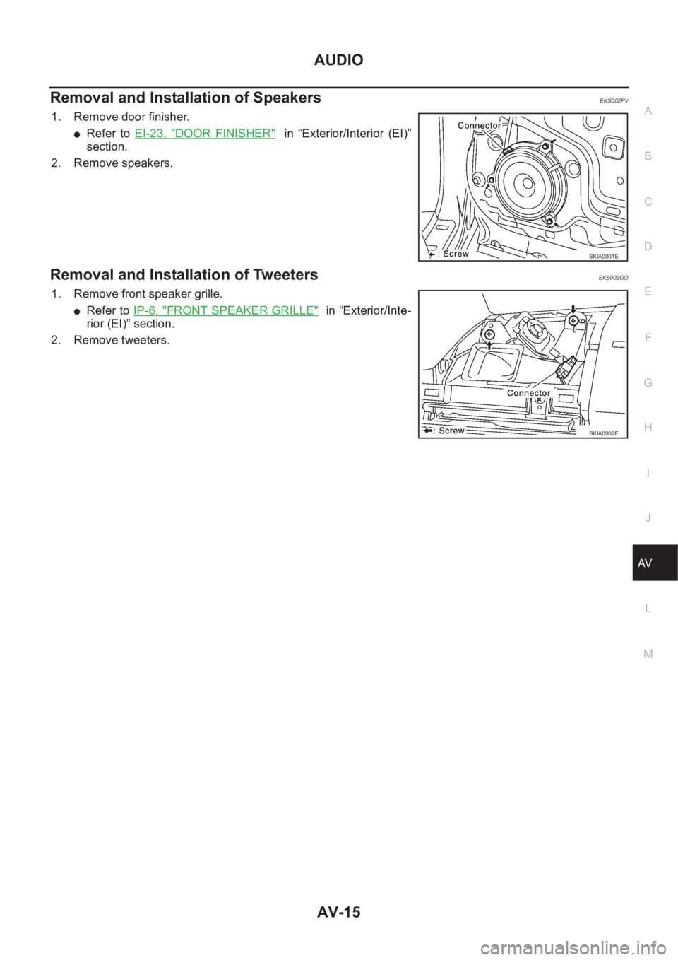
2. Remove speakers.
Removal and Installation of TweetersEKS002GO
1. Remove front speaker grille.
●Refer to IP-6, "FRONT SPEAKER GRILLE" in “Exterior/Inte-
rior (EI)” section.
2. Remove tweeters.
SKIA0001E
SKIA0002E
Page 3704 of 3833
AV-16
AUDIO ANTENNA
AUDIO ANTENNA
PFP:28200
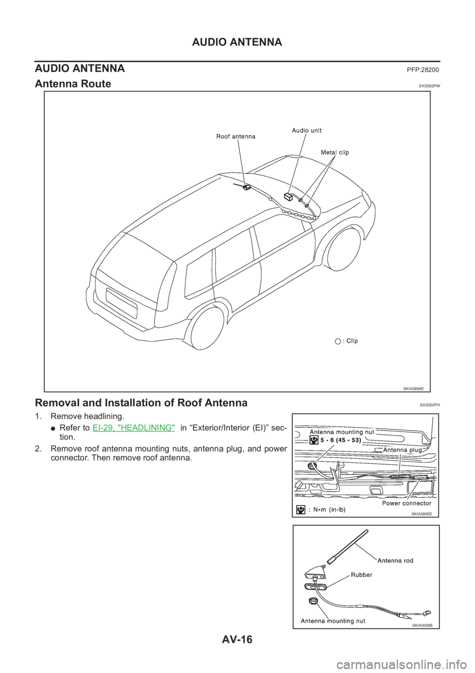
Antenna RouteEKS002PW
Removal and Installation of Roof AntennaEKS002PX
1. Remove headlining.
●Refer to EI-29, "HEADLINING" in “Exterior/Interior (EI)” sec-
tion.
2. Remove roof antenna mounting nuts, antenna plug, and power
connector. Then remove roof antenna.
SKIA0894E
SKIA0895E
SKIA0009E
Page 3705 of 3833
PG-1
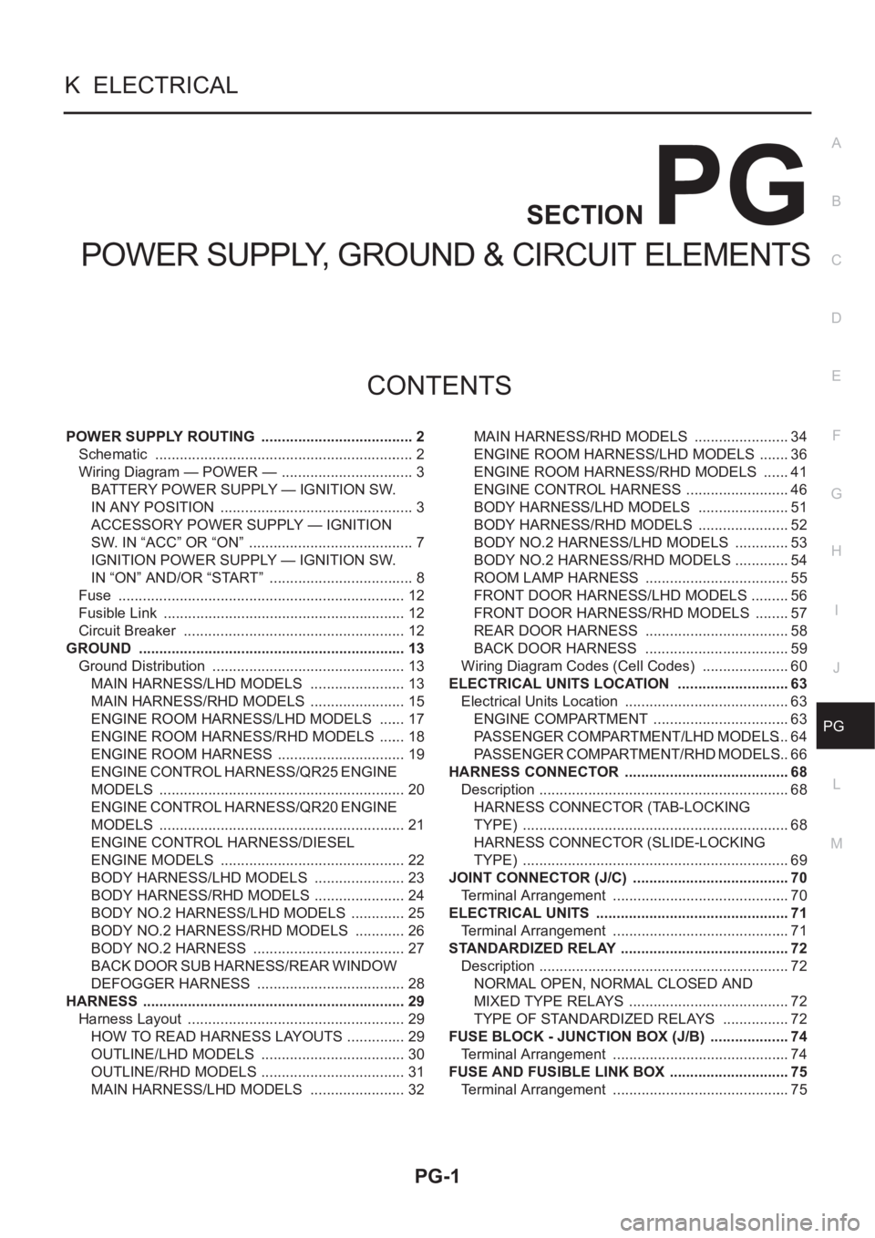
POWER SUPPLY, GROUND & CIRCUIT ELEMENTS
K ELECTRICAL
CONTENTS
C
D
E
F
G
H
I
J
L
M
SECTION
A
B
PG
POWER SUPPLY, GROUND & CIRCUIT ELEMENTS
POWER SUPPLY ROUTING ...................................... 2
Schematic ................................................................ 2
Wiring Diagram — POWER — ................................. 3
BATTERY POWER SUPPLY — IGNITION SW.
IN ANY POSITION ................................................ 3
ACCESSORY POWER SUPPLY — IGNITION
SW. IN “ACC” OR “ON” ......................................... 7
IGNITION POWER SUPPLY — IGNITION SW.
IN “ON” AND/OR “START” .................................... 8
Fuse ....................................................................... 12
Fusible Link ............................................................ 12
Circuit Breaker ....................................................... 12
GROUND .................................................................. 13
Ground Distribution ................................................ 13
MAIN HARNESS/LHD MODELS ........................ 13
MAIN HARNESS/RHD MODELS ........................ 15
ENGINE ROOM HARNESS/LHD MODELS ....... 17
ENGINE ROOM HARNESS/RHD MODELS ....... 18
ENGINE ROOM HARNESS ................................ 19
ENGINE CONTROL HARNESS/QR25 ENGINE
MODELS ............................................................. 20
ENGINE CONTROL HARNESS/QR20 ENGINE
MODELS ............................................................. 21
ENGINE CONTROL HARNESS/DIESEL
ENGINE MODELS .............................................. 22
BODY HARNESS/LHD MODELS ....................... 23
BODY HARNESS/RHD MODELS ....................... 24
BODY NO.2 HARNESS/LHD MODELS .............. 25
BODY NO.2 HARNESS/RHD MODELS ............. 26
BODY NO.2 HARNESS ...................................... 27
BACK DOOR SUB HARNESS/REAR WINDOW
DEFOGGER HARNESS ..................................... 28
HARNESS ................................................................. 29
Harness Layout ...................................................... 29
HOW TO READ HARNESS LAYOUTS ............... 29
OUTLINE/LHD MODELS .................................... 30
OUTLINE/RHD MODELS .................................... 31
MAIN HARNESS/LHD MODELS ........................ 32MAIN HARNESS/RHD MODELS ........................ 34
ENGINE ROOM HARNESS/LHD MODELS ........ 36
ENGINE ROOM HARNESS/RHD MODELS ....... 41
ENGINE CONTROL HARNESS .......................... 46
BODY HARNESS/LHD MODELS ....................... 51
BODY HARNESS/RHD MODELS ....................... 52
BODY NO.2 HARNESS/LHD MODELS .............. 53
BODY NO.2 HARNESS/RHD MODELS .............. 54
ROOM LAMP HARNESS .................................... 55
FRONT DOOR HARNESS/LHD MODELS .......... 56
FRONT DOOR HARNESS/RHD MODELS ......... 57
REAR DOOR HARNESS .................................... 58
BACK DOOR HARNESS .................................... 59
Wiring Diagram Codes (Cell Codes) ...................... 60
ELECTRICAL UNITS LOCATION .........................
... 63
Electrical Units Location ......................................... 63
ENGINE COMPARTMENT .................................. 63
PASSENGER COMPARTMENT/LHD MODELS ... 64
PASSENGER COMPARTMENT/RHD MODELS ... 66
HARNESS CONNECTOR ......................................... 68
Description .............................................................. 68
HARNESS CONNECTOR (TAB-LOCKING
TYPE) .................................................................. 68
HARNESS CONNECTOR (SLIDE-LOCKING
TYPE) .................................................................. 69
JOINT CONNECTOR (J/C) ....................................... 70
Terminal Arrangement ............................................ 70
ELECTRICAL UNITS ................................................ 71
Terminal Arrangement ............................................ 71
STANDARDIZED RELAY .......................................... 72
Description .............................................................. 72
NORMAL OPEN, NORMAL CLOSED AND
MIXED TYPE RELAYS ........................................ 72
TYPE OF STANDARDIZED RELAYS ................. 72
FUSE BLOCK - JUNCTION BOX (J/B) .................... 74
Terminal Arrangement ............................................ 74
FUSE AND FUSIBLE LINK BOX .............................. 75
Terminal Arrangement ............................................ 75
Page 3706 of 3833
PG-2
POWER SUPPLY ROUTING
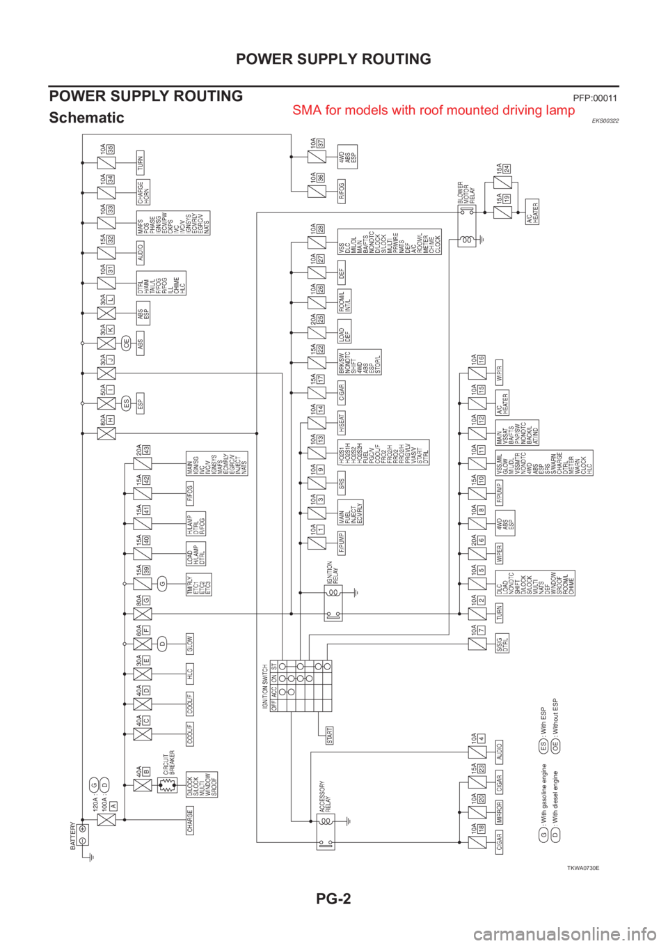
POWER SUPPLY ROUTING
PFP:00011
Schematic EKS00322
TKWA0730E
SMA for models with roof mounted driving lamp
Page 3707 of 3833
POWER SUPPLY ROUTING
PG-3
C
D
E
F
G
H
I
J
L
MA
B
PG
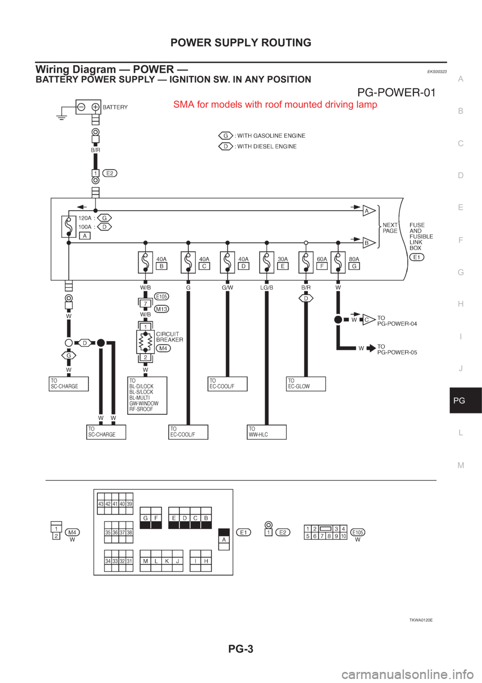
Wiring Diagram — POWER — EKS00323
BATTERY POWER SUPPLY — IGNITION SW. IN ANY POSITION
TKWA0120E
SMA for models with roof mounted driving lamp
Page 3708 of 3833
PG-4
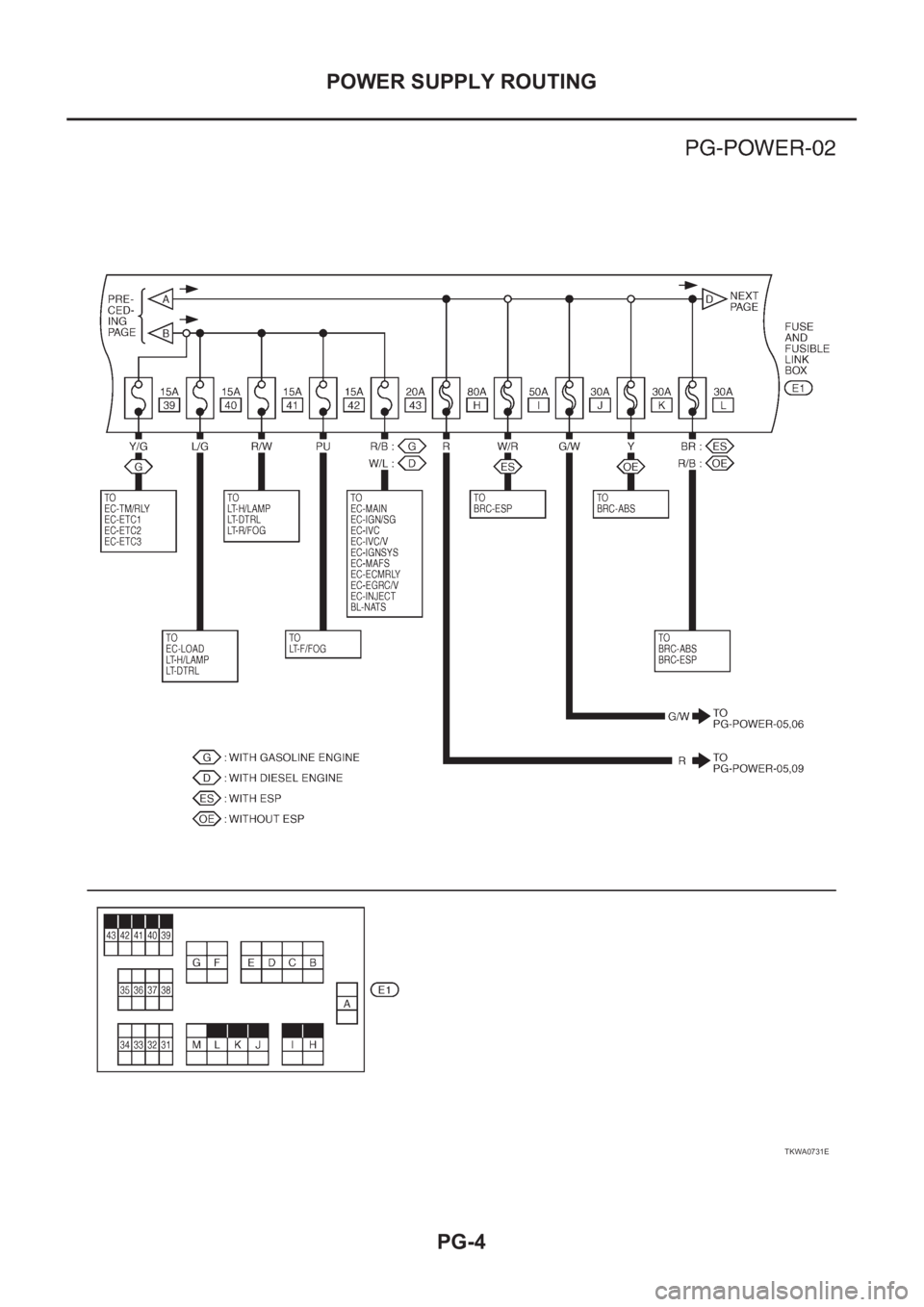
POWER SUPPLY ROUTING
TKWA0731E
Page 3709 of 3833
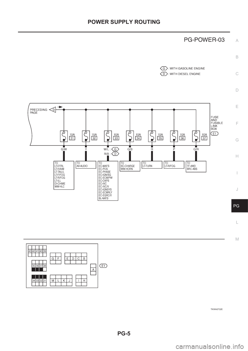
POWER SUPPLY ROUTING
PG-5
C
D
E
F
G
H
I
J
L
MA
B
PG
TKWA0732E
Page 3710 of 3833
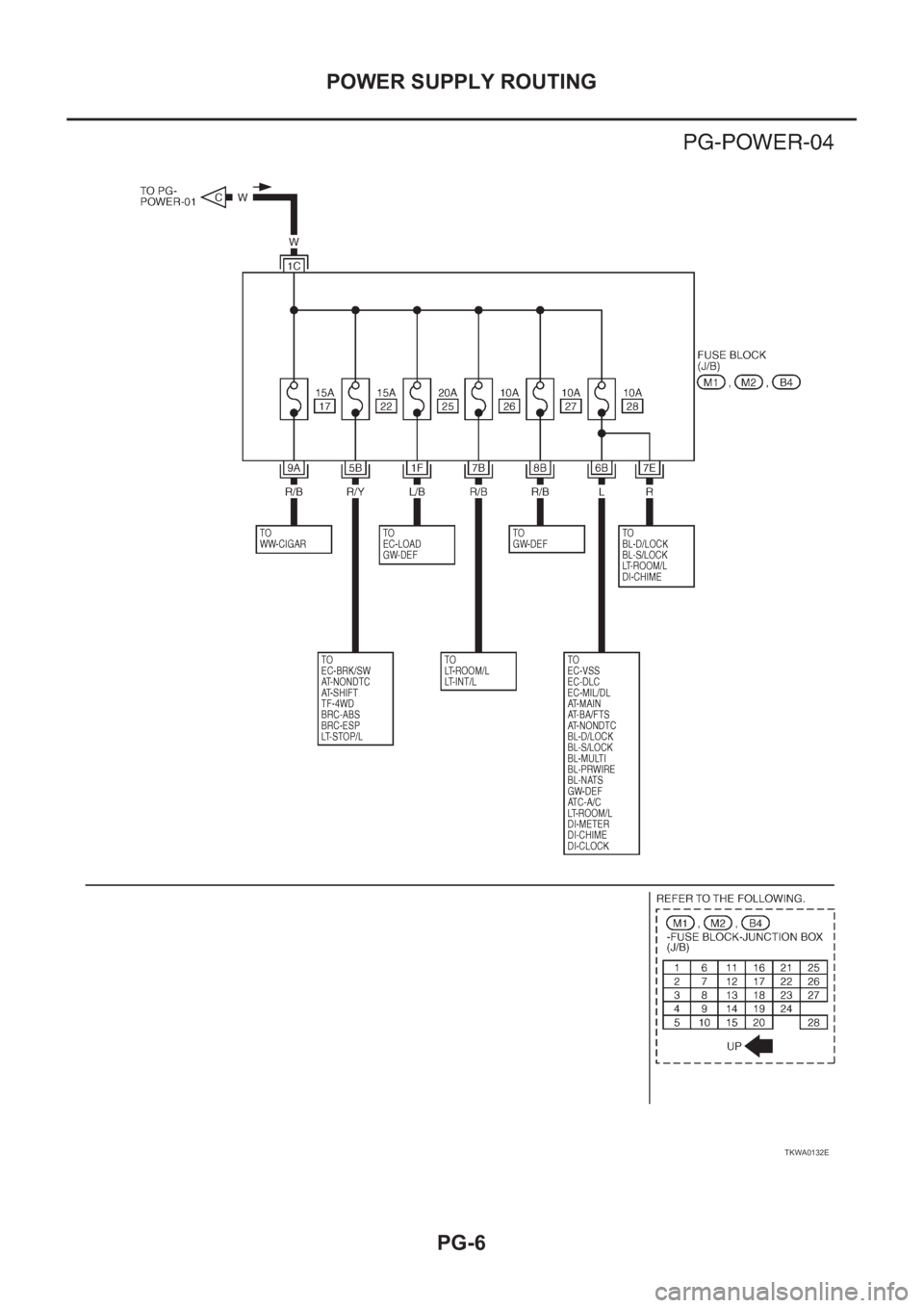
PG-6
POWER SUPPLY ROUTING
TKWA0132E