fuel pump NISSAN X-TRAIL 2003 Electronic Repair Manual
[x] Cancel search | Manufacturer: NISSAN, Model Year: 2003, Model line: X-TRAIL, Model: NISSAN X-TRAIL 2003Pages: 3066, PDF Size: 51.47 MB
Page 2234 of 3066
![NISSAN X-TRAIL 2003 Electronic Repair Manual FUEL LEVEL SENSOR UNIT
FL-19
[YD22DDTi]
C
D
E
F
G
H
I
J
K
L
MA
FL
lTo keep clean the connecting portion and to avoid damage
and foreign materials, cover them completely with plastic
bags or something NISSAN X-TRAIL 2003 Electronic Repair Manual FUEL LEVEL SENSOR UNIT
FL-19
[YD22DDTi]
C
D
E
F
G
H
I
J
K
L
MA
FL
lTo keep clean the connecting portion and to avoid damage
and foreign materials, cover them completely with plastic
bags or something](/img/5/57402/w960_57402-2233.png)
FUEL LEVEL SENSOR UNIT
FL-19
[YD22DDTi]
C
D
E
F
G
H
I
J
K
L
MA
FL
lTo keep clean the connecting portion and to avoid damage
and foreign materials, cover them completely with plastic
bags or something similar.
8. Using a lock ring wrench, remove the lock ring.
9. Remove main fuel level sensor unit and sub fuel level sensor
unit.
CAUTION:
lDo not bend the float arm during removal.
lAvoid impacts such as falling when handling components.
Removal of main fuel level sensor unit:
lRaise the fuel level sensor unit, and remove the jet pump.
lLeave the jet pump on the fuel tank with the fuel hose.
lIf necessary, remove the chamber from the bottom of the fuel
tank.
lRemove the chamber by sliding toward the rear of the vehicle.
Removal of sub fuel level sensor unit:
lRaise and release the sub fuel level sensor unit to remove.
lIf necessary, remove the jet pump inlet from the bottom of the fuel tank.
To remove it, pinch the tabs (2 places).
INSPECTION AFTER REMOVAL
Make sure the fuel pump strainer is free from foreign materials, If any are found, remove them.
INSTALLATION
Install in the reverse order of removal paying attention to the follow-
ing.
lWhen installing the chamber and jet pump, insert them fully until
a click sound of full stopper engagement is heard (for jet pump
inlet).
lConnect the quick connector as follows.
1. Check the connection for damage and foreign materials.
2. Align the connector with the tube, then insert the connector
straight into the tube until a click is heard.
3. After connecting, make sure that the connection is secure by fol-
lowing the steps below.
PBIC0163E
PBIC0240E
SBIA0142E
SBIA0143E
Page 2257 of 3066
GI-4
PRECAUTIONS
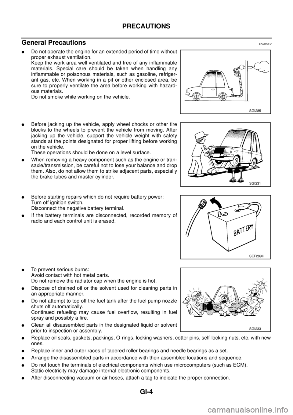
General Precautions
EAS000FQ
lDo not operate the engine for an extended period of time without
proper exhaust ventilation.
Keep the work area well ventilated and free of any inflammable
materials. Special care should be taken when handling any
inflammable or poisonous materials, such as gasoline, refriger-
ant gas, etc. When working in a pit or other enclosed area, be
sure to properly ventilate the area before working with hazard-
ous materials.
Do not smoke while working on the vehicle.
lBefore jacking up the vehicle, apply wheel chocks or other tire
blocks to the wheels to prevent the vehicle from moving. After
jacking up the vehicle, support the vehicle weight with safety
stands at the points designated for proper lifting before working
on the vehicle.
These operations should be done on a level surface.
lWhen removing a heavy component such as the engine or tran-
saxle/transmission, be careful not to lose your balance and drop
them. Also, do not allow them to strike adjacent parts, especially
the brake tubes and master cylinder.
lBefore starting repairs which do not require battery power:
Turn off ignition switch.
Disconnect the negative battery terminal.
lIf the battery terminals are disconnected, recorded memory of
radio and each control unit is erased.
lTo prevent serious burns:
Avoid contact with hot metal parts.
Do not remove the radiator cap when the engine is hot.
lDispose of drained oil or the solvent used for cleaning parts in
an appropriate manner.
lDo not attempt to top off the fuel tank after the fuel pump nozzle
shuts off automatically.
Continued refueling may cause fuel overflow, resulting in fuel
spray and possibly a fire.
lClean all disassembled parts in the designated liquid or solvent
prior to inspection or assembly.
lReplace oil seals, gaskets, packings, O-rings, locking washers, cotter pins, self-locking nuts, etc. with new
ones.
lReplace inner and outer races of tapered roller bearings and needle bearings as a set.
lArrange the disassembled parts in accordance with their assembled locations and sequence.
lDo not touch the terminals of electrical components which use microcomputers (such as ECM).
Static electricity may damage internal electronic components.
lAfter disconnecting vacuum or air hoses, attach a tag to indicate the proper connection.
SGI285
SGI231
SEF289H
SGI233
Page 2259 of 3066
GI-6
PRECAUTIONS
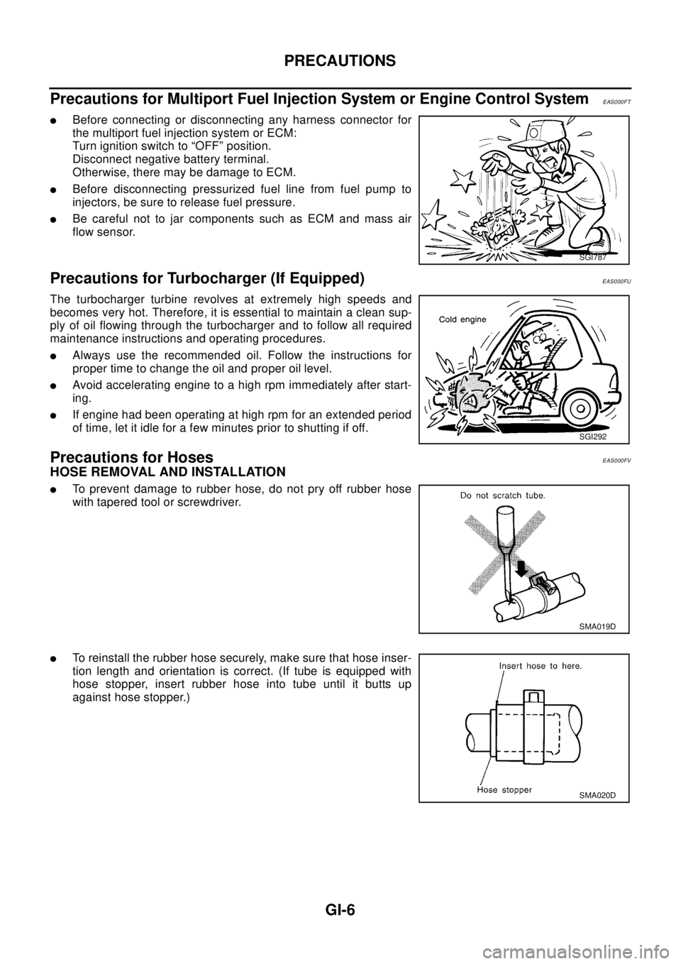
Precautions for Multiport Fuel Injection System or Engine Control System
EAS000FT
lBefore connecting or disconnecting any harness connector for
the multiport fuel injection system or ECM:
Turn ignition switch to “OFF” position.
Disconnect negative battery terminal.
Otherwise, there may be damage to ECM.
lBefore disconnecting pressurized fuel line from fuel pump to
injectors, be sure to release fuel pressure.
lBe careful not to jar components such as ECM and mass air
flow sensor.
Precautions for Turbocharger (If Equipped)EAS000FU
The turbocharger turbine revolves at extremely high speeds and
becomes very hot. Therefore, it is essential to maintain a clean sup-
ply of oil flowing through the turbocharger and to follow all required
maintenance instructions and operating procedures.
lAlways use the recommended oil. Follow the instructions for
proper time to change the oil and proper oil level.
lAvoid accelerating engine to a high rpm immediately after start-
ing.
lIf engine had been operating at high rpm for an extended period
of time, let it idle for a few minutes prior to shutting if off.
Precautions for HosesEAS000FV
HOSE REMOVAL AND INSTALLATION
lTo prevent damage to rubber hose, do not pry off rubber hose
with tapered tool or screwdriver.
lTo reinstall the rubber hose securely, make sure that hose inser-
tion length and orientation is correct. (If tube is equipped with
hose stopper, insert rubber hose into tube until it butts up
against hose stopper.)
SGI787
SGI292
SMA019D
SMA020D
Page 2302 of 3066

TERMINOLOGY
GI-49
Nonvolatile random access memory NVRAM ***
On board diagnostic system OBD system Self-diagnosis
Open loop OL Open loop
Oxidation catalyst OC Catalyst
Oxidation catalytic converter system OC system ***
Oxygen sensor O2S Exhaust gas sensor
Park position switch *** Park switch
Park/neutral position switch PNP switchPark/neutral switch
Inhibitor switch
Neutral position switch
Periodic trap oxidizer system PTOX system ***
Positive crankcase ventilation PCV Positive crankcase ventilation
Positive crankcase ventilation valve PCV valve PCV valve
Powertrain control module PCM ***
Programmable read only memory PROM ***
Pulsed secondary air injection control sole-
noid valvePAIRC solenoid valve AIV control solenoid valve
Pulsed secondary air injection system PAIR system Air induction valve (AIV) control
Pulsed secondary air injection valve PAIR valve Air induction valve
Random access memory RAM ***
Read only memory ROM ***
Scan tool ST ***
Secondary air injection pump AIR pump ***
Secondary air injection system AIR system ***
Sequential multiport fuel injection system SFI system Sequential fuel injection
Service reminder indicator SRI ***
Simultaneous multiport fuel injection sys-
tem*** Simultaneous fuel injection
Smoke puff limiter system SPL system ***
Supercharger SC ***
Supercharger bypass SCB ***
System readiness test SRT ***
Thermal vacuum valve TVV Thermal vacuum valve
Three way catalyst TWC Catalyst
Three way catalytic converter system TWC system ***
Three way + oxidation catalyst TWC + OC Catalyst
Three way + oxidation catalytic converter
systemTWC + OC system ***
Throttle body TBThrottle chamber
SPI body
Throttle body fuel injection system TBI system Fuel injection control
Throttle position TP Throttle position
Throttle position sensor TPS Throttle sensor
Throttle position switch TP switch Throttle switchNEW TERMNEW ACRONYM /
ABBREVIATIONOLD TERM
Page 2361 of 3066
IDX-4
ALPHABETICAL INDEX
Diagnostic trouble code (DTC) ........................EC-666
Diagnostic trouble code (DTC) for OBD systemEC-12,
EC-38
,EC-379,EC-401,EC-654
Diagnostic trouble code (DTC) inspection priority chart
EC-61
,EC-410
Differential gear (FF M/T) .....................MT-22,MT-27
DLC - Wiring diagram ........................EC-371,EC-646
Door glass ...........................................GW-41,GW-43
Door glass Fitting Adjustment .............GW-41,GW-43
Door lock .................................................BL-54,BL-57
Door mirror ........................................................GW-46
Door trim .............................................................EI-23
Door, front ............................................................BL-8
Door, rear .............................................................BL-8
Drive belt inspection(QR20DE) .........................MA-20
Drive belt inspection(YD22DDTi) ......................MA-27
Drive belt(QR20DE) ..........................................EM-13
Drive belt(YD22DDTi) .....................................EM-110
Drive shaft (front) .............................................FAX-11
Drive shaft (rear) ...............................................RAX-9
Driver air bag ..................................................SRS-27
Dropping resistor (A/T) ......................AT-192,AT-442
DTC work support ..............................................EC-95
DTRL - Wiring diagram .........................................LT-9
Dual pressure switch ........ATC-16,ATC-81,ATC-138
Duct and grilles ...............................ATC-121,MTC-29
E
ECM input/output signal .......................EC-79
,EC-427
ECM power supplyEC-108,EC-256,EC-454,EC-530,
EC-700
ECM relay ........................................................EC-790
ECM/PW - Wiring diagram .................EC-257,EC-531
ECMRLY - Wiring diagram ..............................EC-791
ECTS - Wiring diagram .......EC-143,EC-472,EC-712
EDU - Wiring diagram ......................................EC-756
EGR function ...................................................EC-803
EGR volume control valve ...............................EC-803
EGRC/V - Wiring diagram ................................EC-805
Electric sun roof ...................................................RF-2
Electric throttle control actuator ........EC-271,EC-273,
EC-534
,EC-536
Electrical unit .....................................................PG-73
Electrical units location ......................................PG-64
Electronic drive unit (EDU) ..............................EC-754
Electronic fuel injection pump(YD22DDTi) .....EM-138
Electronic ignition (EI) system .............EC-27,EC-392
Engine control circuit diagramEC-77,EC-425,EC-683
Engine control component parts location ..........EC-73,
EC-421
Engine control module (ECM) ...........EC-249,EC-523,
EC-788
Engine control system diagram and chart ........EC-22,
EC-387
,EC-659
Engine coolant temperature sensor (ECTS) ...EC-141,
EC-470
,EC-711
Engine coolant(QR20DE) ...................................CO-9
Engine coolant(YD22DDTi) ..............................CO-30
Engine fail-safe system .......................EC-62,EC-411
Engine oil filter replacement(QR20DE) .............MA-24
Engine oil filter replacement(YD22DDTi) ..........MA-33
Engine oil replacement(QR20DE) ....................MA-24
Engine oil replacement(YD22DDTi) ..................MA-32
Engine oil(QR20DE) ............................................LU-7
Engine oil(YD22DDTi) .......................................LU-18
Engine removal(QR20DE) ................................EM-61
Engine removal(YD22DDTi) ...........................EM-184
EVAP canister purge volume control solenoid valve ....
EC-233
,EC-372,EC-601,EC-649
EVAP vapor lines inspection(QR20DE) ............MA-26
Evaporative emission (EVAP) systemEC-372,EC-647
Evaporator ....................................................ATC-139
Exhaust manifold(QR20DE) .............................EM-22
Exhaust manifold(YD22DDTi) .........................EM-119
Exhaust system ...................................................EX-2
Exhaust system inspection .....................EX-2,MA-35
Expansion valve ............................................ATC-140
ExteriorEI-13,EI-14,EI-16,EI-17,EI-18,EI-19,EI-21,
EI-22
F
F/FOG - Wiring diagram .........................LT-33
,LT-34
F/PUMP - Wiring diagram .................EC-354,EC-629
Fan control amp. .............................ATC-70,ATC-113
Fan switch ........................................ATC-27,MTC-17
FIAR - Wiring diagram .....................................EC-778
Final drive (FF M/T) ..............................MT-22,MT-27
Final drive disassembly ..................................RFD-11
Final drive removal and installation ................RFD-11
Finisher, interior - See Trim ......................EI-23,EI-25
Finisher, rear panel .............................................EI-22
Floor trim .............................................................EI-28
Fluid temperature sensor (A/T) ........................AT-141
Fluids ................................................................MA-17
Fluorescent leak detector .............................ATC-141
Flywheel (clutch) ................................................CL-15
Flywheel runout(QR20DE) ................................EM-89
Flywheel runout(YD22DDTi) ...........................EM-208
Fog lamp, front ...................................................LT-33
Fork rod (M/T) .......................................MT-21,MT-26
Freeze frame data ..............................EC-39,EC-402
FRO2 - Wiring diagram ....................................EC-582
FRO2/H - Wiring diagram ................................EC-569
Front bumper ........................................................EI-6
Front disc brake .................................................BR-21
Front door ............................................................BL-8
Front Door Trim ..................................................EI-23
Front fog lamp ....................................................LT-33
Front passenger air bag ..................................SRS-33
Front seat .............................................................SE-7
Front seat belt ......................................................SB-3
Front seat belt pre-tensioner .....SB-2,SRS-3,SRS-38
Front side air bag ............................................SRS-35
Front suspension ..............................................FSU-5
Page 2362 of 3066
IDX-5
A
C
D
E
F
G
H
I
J
K
L B
IDX
ALPHABETICAL INDEX
Front washer ......................................................WW-4
Front wiper .........................................................WW-4
FTS - Wiring diagram ......................................EC-752
Fuel check valve ..............................................EC-372
Fuel cut control (at no load high engine speed)EC-28,
EC-393
,EC-662
Fuel filler lid ........................................................BL-64
Fuel filter ..........................................................EC-664
Fuel filter replacement(QR20DE) .........................FL-4
Fuel filter replacement(YD22DDTi) .......FL-15,MA-30
Fuel gauge ..................................................DI-4,DI-22
Fuel injection control system ...........................EC-660
Fuel injection system .........................EC-194,EC-200
Fuel injector .....................................................EC-727
Fuel injector adjustment resistor ......................EC-777
Fuel injector and fuel tube(QR20DE) ................EM-29
Fuel injector and fuel tube(YD22DDTi) ............EM-135
Fuel leak ..........................................................EC-781
Fuel line inspection(QR20DE) .................FL-3,MA-23
Fuel line inspection(YD22DDTi) ............FL-14,MA-30
Fuel pressure check ............................EC-34,EC-399
Fuel pressure release ..........................EC-34,EC-399
Fuel pressure relief valve ................................EC-665
Fuel pump ..........................................EC-352,EC-627
Fuel pump and gauge(QR20DE) ..........................FL-4
Fuel system(QR20DE) .........................................FL-3
Fuel system(YD22DDTi) .....................................FL-14
Fuel tank(QR20DE) ..............................................FL-9
Fuel tank(YD22DDTi) .........................................FL-21
Fuel temperature sensor .................................EC-751
Fuse ...................................................................PG-12
Fuse and fusible link box ...................................PG-77
Fusible link .........................................................PG-12
G
Gear components (M/T) .......................MT-19
,MT-24
Generator ..........................................................SC-12
Generator - See Alternator ................................SC-12
Generic scan tool (GST) ....................................EC-96
Glass ..................................................GW-41,GW-43
GLOW - Wiring diagram ..................................EC-797
Glow plug .........................................................EC-796
Glow plug(YD22DDTi) .....................................EM-130
Glow relay ........................................................EC-796
Grease ...............................................................MA-17
Grille - See Exterior .............................................EI-11
Ground distribution ............................................PG-13
G-sensor .............................................................TF-50
H
H/AIM - Wiring diagram ......................................LT-15
H/LAMP - Wiring diagram ...........................LT-4,LT-5
H/MIRROR - Wiring diagram ............................GW-10
Harness connector ............................................PG-70
Harness layout ...................................................PG-29
Headlamp .............................................................LT-4
Headlamp aiming control ....................................LT-15
Headlamp leveler - See Headlamp aiming control .......
LT-15
Headlamp washer ............................................WW-19
Headlining - See Roof trim ..................................EI-29
Heated oxygen sensor 1 ....EC-160,EC-166,EC-174,
EC-284
,EC-290,EC-490,EC-581
Heated oxygen sensor 1 heater .........EC-120,EC-568
Heated oxygen sensor 2 ....EC-181,EC-187,EC-296,
EC-303
,EC-587
Heated oxygen sensor 2 heater .........EC-125,EC-573
Heated seat ...............................................SE-3,SE-5
HEATER - Wiring diagram ................................MTC-6
Heater and cooling unit (Heater core) ............ATC-115
Heater mirror .....................................................GW-10
Heater system - Wiring diagram .......................MTC-6
Heater unit (heater core) ..ATC-120,MTC-23,MTC-26
HFC134a (R134a) system precaution ...............ATC-4
HFC134a (R134a) system service procedureATC-123
HFC134a (R134a) system service tools ..........ATC-12
HFC134a system service equipment precautionATC-8
HO2S1 - Wiring diaram ......EC-122,EC-162,EC-169,
EC-177
,EC-492
HO2S2 - Wiring diagram ....EC-183,EC-190,EC-299,
EC-306
HO2S2H - Wiring diagram ...............................EC-127
Hood ....................................................................BL-4
Horn .................................................................WW-23
HORN - Wiring diagram ...................................WW-23
How to erase DTC ...........................................EC-666
HowtoeraseDTCforOBDsystem .....EC-46,EC-402
I
IATS - Wiring diagram .....................................EC-138
IATSEN - Wiring diagram ................................EC-578
Identification .....................................................ATC-10
Idle air volume learning ........................EC-31,EC-396
Idle speed .............................EC-64,EC-412,EC-672
IGN/SG - Wiring diagram .................................EC-335
Ignition coil .........................................EC-334,EC-592
Ignition coil(QR20DE) .......................................EM-27
Ignition control system .......................EC-334,EC-592
Ignition timing .......................................EC-64,EC-412
IGNSYS - Wiring diagram ................................EC-593
ILL - Wiring diagram ...........................................LT-45
Illumination ..........................................................LT-45
In vehicle sensor ...............ATC-95,ATC-97,ATC-106
INJECT - Wiring diagram ....EC-344,EC-619,EC-730
Injection nozzle(YD22DDTi) ...........................EM-135
Injector ...............................................EC-343,EC-618
Input shaft (FF M/T) ..............................MT-19,MT-24
Instrument panel ...................................................IP-3
INT/L - Wiring diagram ........................................LT-65
Intake air temparature sensor ............EC-136,EC-577
Intake door control linkage adjustment ............ATC-66
Intake door motorATC-64,ATC-112,MTC-10,MTC-22
Intake manifold(QR20DE) .................................EM-17
Page 2363 of 3066
IDX-6
ALPHABETICAL INDEX
Intake manifold(YD22DDTi) ............................EM-115
Intake sensor ................................ATC-101,ATC-108
Intake valve timing control .................EC-117,EC-608
Intake valve timing control solenoid valve ......EC-266,
EC-608
Interior .......................EI-23,EI-25,EI-26,EI-28,EI-29
Interior lamp ........................................................LT-55
Interior lamp on-off control ......................LT-55,LT-56
ISO 15031-5 Mode 1 - 9 ....................................EC-36
IVC - Wiring diagram .......................................EC-268
IVC/V - Wiring diagram ....................................EC-610
J
Joint connector (J/C) .............................PG-72
,PG-76
K
Keyless entry system - See Multi-remote control system
BL-45
Knock sensor (KS) .............................EC-212,EC-496
KS - Wiring diagram ...........................EC-214,EC-498
L
LAN system circuit ...........................................ATC-56
License lamp .......................................................LT-30
Line pressure solenoid valve ...........................AT-179
Line pressure test (A/T) .......................AT-68,AT-290
Liquid gasket application(QR20DE) ....................EM-6
Liquid gasket application(YD22DDTi) .............EM-103
LOAD - Wiring diagram ......................EC-363,EC-638
Location of electrical units .................................PG-64
Lock, door ...............................................BL-54,BL-57
Lubricant (R134a) A/C ........................ATC-5,ATC-21
Lubricants .........................................................MA-17
Lubrication circuit (engine)(QR20DE) ..................LU-5
Lubrication circuit (engine)(YD22DDTi) .............LU-17
Lubrication-locks, hinges and hood latches ......MA-42
M
M/T major overhaul ...............................MT-27
,MT-35
M/T oil replacement ...........................................MT-11
M/T removal and installation ..............................MT-16
MAFS - Wiring diagram .....EC-132,EC-262,EC-466,
EC-708
Magnet clutch .................................ATC-73,ATC-129
MAIN - Wiring diagram .......EC-108,EC-454,EC-701
Mainshaft (M/T) .....................................MT-19,MT-24
Major overhaul (Transfer) ..................................TF-14
Malfunction indicator (MI) ...EC-252,EC-526,EC-667
Malfunction indicator lamp (MIL) ..........EC-48,EC-404
Mass air flow sensor (MAFS) ............EC-130,EC-260,
EC-463
,EC-706
Master cylinder (brake) ......................................BR-13
Master cylinder (clutch) ........................................CL-9
METER - Wiring diagram ...........................DI-8,DI-26
MIL - Wiring diagram ........................EC-253,EC-527
MIL/DL - Wiring diagram ..................................EC-825
MIRROR - Wiring diagram ...............................GW-47
Mirror defogger ................................................GW-10
Mirror, door ......................................................GW-46
Mirror, out side .................................................GW-46
Misfire ..............................................................EC-206
Mode door control linkage adjustment ...........ATC-61,
ATC-118
,MTC-8,MTC-27
Mode door motor ............................ATC-58,ATC-118
Molding - See Exterior ........GW-3,EI-14,EI-16,EI-17
Mud guard - See Exterior ....................................EI-16
MULTI - Wiring diagram .....................................BL-47
Multiport fuel injection (MFI) system ...EC-24,EC-389
Multi-remote control system ...............................BL-45
N
NATS - Wiring diagram ......................................BL-72
NATS (Nissan anti-theft system) .......................BL-70
NVH troubleshooting (BR) .........................BR-5,PB-2
NVH troubleshooting (CL) ....................................CL-4
NVH troubleshooting (EM)(QR20DE) ...............EM-11
NVH troubleshooting (EM)(YD22DDTi) ..........EM-108
NVH troubleshooting (FSU) ..............................FSU-4
NVH troubleshooting (M/T) .................................MT-8
NVH troubleshooting (PR) .................................FAX-6
NVH troubleshooting (RA) ................................RAX-5
NVH troubleshooting (RAX) ..............................RAX-5
NVH troubleshooting (RSU) ..............................RSU-4
NVH troubleshooting (ST) ....................................PS-4
NVH troubleshooting (Transfer) ...........................TF-7
NVH troubleshooting (WT) ..................................WT-2
O
Oil cooler (engine)(QR20DE) .............................LU-13
Oil cooler (engine)(YD22DDTi) ..........................LU-25
Oil filter(QR20DE) ................................................LU-9
Oil filter(YD22DDTi) ...........................................LU-20
Oil pan (engine)(QR20DE) ...............................EM-24
Oil pan (engine)(YD22DDTi) ...........................EM-125
Oil pressure (engine)(QR20DE) ..........................LU-7
Oil pressure (engine)(YD22DDTi) ......................LU-18
Oil pump (engine)(QR20DE) .............................LU-10
Oil pump (engine)(YD22DDTi) ...........................LU-23
Oil pump regulator valve (engine)(QR20DE) .....LU-11
Oil pump regulator valve (engine)(YD22DDTi) ..LU-24
On board diagnostic system ...............EC-36,EC-401
Operating cylinder (clutch) .................................CL-11
Out side mirror .................................................GW-46
Overdrive control switch ....................AT-265,AT-387
Overheat ..........................................................EC-761
Oversize piston(QR20DE) ................................EM-85
Oversize piston(YD22DDTi) ...........................EM-204
Page 2526 of 3066
MA-34
ENGINE MAINTENANCE (YD22DDTI)
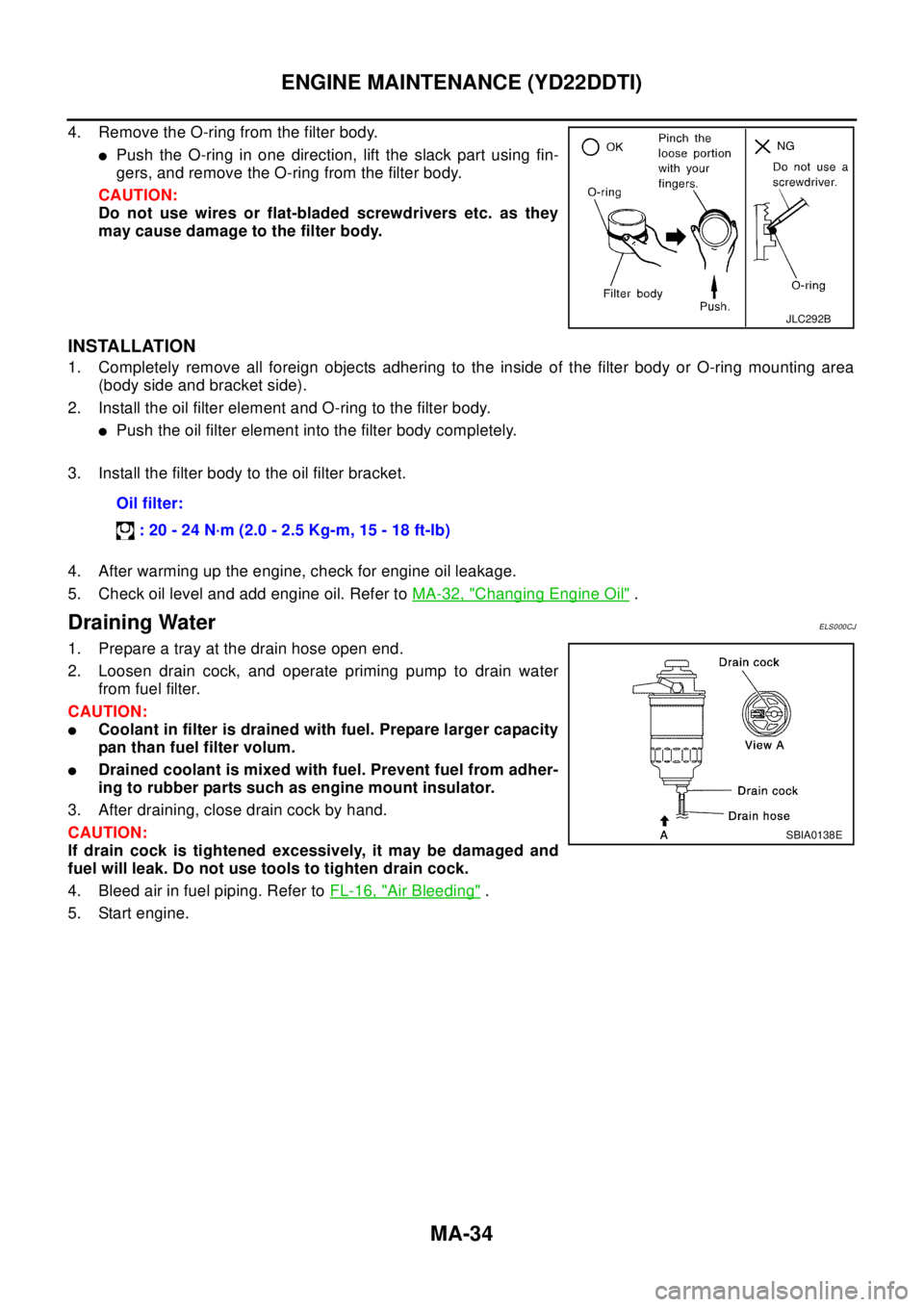
4. Remove the O-ring from the filter body.
lPush the O-ring in one direction, lift the slack part using fin-
gers, and remove the O-ring from the filter body.
CAUTION:
Do not use wires or flat-bladed screwdrivers etc. as they
may cause damage to the filter body.
INSTALLATION
1. Completely remove all foreign objects adhering to the inside of the filter body or O-ring mounting area
(body side and bracket side).
2. Install the oil filter element and O-ring to the filter body.
lPush the oil filter element into the filter body completely.
3. Install the filter body to the oil filter bracket.
4. After warming up the engine, check for engine oil leakage.
5. Check oil level and add engine oil. Refer toMA-32, "
Changing Engine Oil".
Draining WaterELS000CJ
1. Prepare a tray at the drain hose open end.
2. Loosen drain cock, and operate priming pump to drain water
from fuel filter.
CAUTION:
lCoolant in filter is drained with fuel. Prepare larger capacity
pan than fuel filter volum.
lDrained coolant is mixed with fuel. Prevent fuel from adher-
ing to rubber parts such as engine mount insulator.
3. After draining, close drain cock by hand.
CAUTION:
If drain cock is tightened excessively, it may be damaged and
fuel will leak. Do not use tools to tighten drain cock.
4. Bleed air in fuel piping. Refer toFL-16, "
Air Bleeding".
5. Start engine.
JLC292B
Oil filter:
:20-24N·m(2.0-2.5Kg-m,15-18ft-lb)
SBIA0138E