door locks NISSAN X-TRAIL 2003 Electronic User Guide
[x] Cancel search | Manufacturer: NISSAN, Model Year: 2003, Model line: X-TRAIL, Model: NISSAN X-TRAIL 2003Pages: 3066, PDF Size: 51.47 MB
Page 769 of 3066

POWER DOOR LOCK — SUPER LOCK —
BL-25
C
D
E
F
G
H
J
K
L
MA
B
BL
Lock/unlock switch operation cannot control super lock
Key reminder system
lIf the ignition key is in the ignition key cylinder and driver door is open, setting lock/unlock switch, lock
knob, key or multi-remote controller to “LOCK” locks the door once but then immediately unlocks all doors.
(signal from door unlock sensor driver side)
System initialization
lSystem initialization is required when battery cables are reconnected. Conduct the following to release
super lock once;
–insert the key into the ignition key cylinder and turn it to ON.
–LOCK/UNLOCK operation using door key cylinder or multi-remote controller.
Page 780 of 3066
BL-36
POWER DOOR LOCK — SUPER LOCK —
Power Supply and Ground Circuit Check
EIS001SS
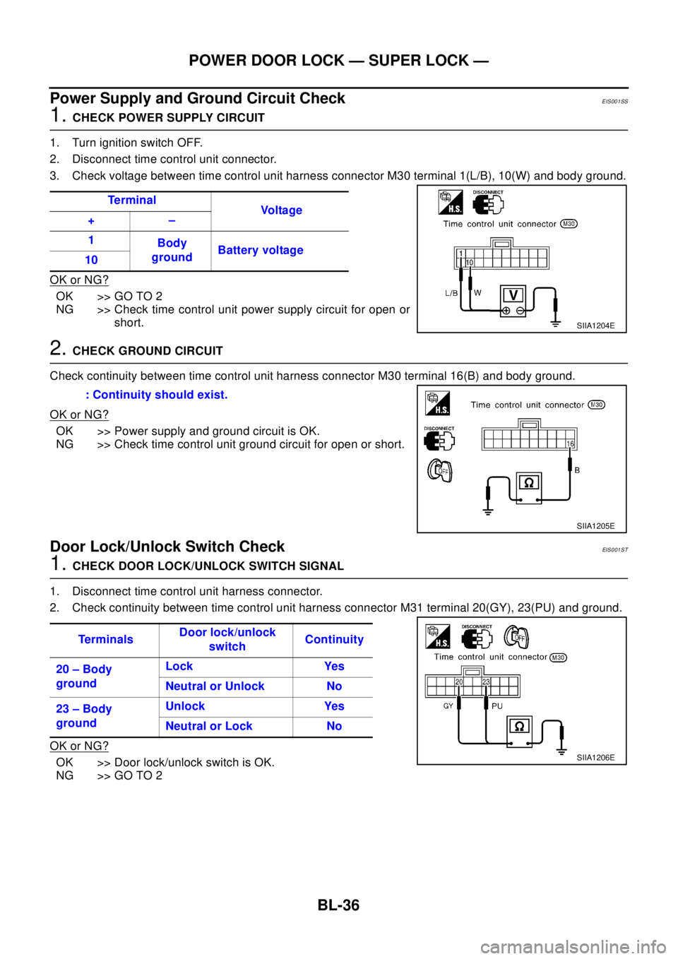
1.CHECK POWER SUPPLY CIRCUIT
1. Turn ignition switch OFF.
2. Disconnect time control unit connector.
3. Check voltage between time control unit harness connector M30 terminal 1(L/B), 10(W) and body ground.
OK or NG?
OK >> GO TO 2
NG >> Check time control unit power supply circuit for open or
short.
2.CHECK GROUND CIRCUIT
Check continuity between time control unit harness connector M30 terminal 16(B) and body ground.
OK or NG?
OK >> Power supply and ground circuit is OK.
NG >> Check time control unit ground circuit for open or short.
Door Lock/Unlock Switch CheckEIS001ST
1.CHECKDOORLOCK/UNLOCKSWITCHSIGNAL
1. Disconnect time control unit harness connector.
2. Check continuity between time control unit harness connector M31 terminal 20(GY), 23(PU) and ground.
OK or NG?
OK >> Door lock/unlock switch is OK.
NG >> GO TO 2Te r m i n a l
Vo l ta g e
+–
1
Body
groundBattery voltage
10
SIIA1204E
: Continuity should exist.
SIIA1205E
Te r m i n a l sDoor lock/unlock
switchContinuity
20 – Body
groundLock Yes
Neutral or Unlock No
23 – Body
groundUnlock Yes
Neutral or Lock No
SIIA1206E
Page 2363 of 3066
IDX-6
ALPHABETICAL INDEX
Intake manifold(YD22DDTi) ............................EM-115
Intake sensor ................................ATC-101,ATC-108
Intake valve timing control .................EC-117,EC-608
Intake valve timing control solenoid valve ......EC-266,
EC-608
Interior .......................EI-23,EI-25,EI-26,EI-28,EI-29
Interior lamp ........................................................LT-55
Interior lamp on-off control ......................LT-55,LT-56
ISO 15031-5 Mode 1 - 9 ....................................EC-36
IVC - Wiring diagram .......................................EC-268
IVC/V - Wiring diagram ....................................EC-610
J
Joint connector (J/C) .............................PG-72
,PG-76
K
Keyless entry system - See Multi-remote control system
BL-45
Knock sensor (KS) .............................EC-212,EC-496
KS - Wiring diagram ...........................EC-214,EC-498
L
LAN system circuit ...........................................ATC-56
License lamp .......................................................LT-30
Line pressure solenoid valve ...........................AT-179
Line pressure test (A/T) .......................AT-68,AT-290
Liquid gasket application(QR20DE) ....................EM-6
Liquid gasket application(YD22DDTi) .............EM-103
LOAD - Wiring diagram ......................EC-363,EC-638
Location of electrical units .................................PG-64
Lock, door ...............................................BL-54,BL-57
Lubricant (R134a) A/C ........................ATC-5,ATC-21
Lubricants .........................................................MA-17
Lubrication circuit (engine)(QR20DE) ..................LU-5
Lubrication circuit (engine)(YD22DDTi) .............LU-17
Lubrication-locks, hinges and hood latches ......MA-42
M
M/T major overhaul ...............................MT-27
,MT-35
M/T oil replacement ...........................................MT-11
M/T removal and installation ..............................MT-16
MAFS - Wiring diagram .....EC-132,EC-262,EC-466,
EC-708
Magnet clutch .................................ATC-73,ATC-129
MAIN - Wiring diagram .......EC-108,EC-454,EC-701
Mainshaft (M/T) .....................................MT-19,MT-24
Major overhaul (Transfer) ..................................TF-14
Malfunction indicator (MI) ...EC-252,EC-526,EC-667
Malfunction indicator lamp (MIL) ..........EC-48,EC-404
Mass air flow sensor (MAFS) ............EC-130,EC-260,
EC-463
,EC-706
Master cylinder (brake) ......................................BR-13
Master cylinder (clutch) ........................................CL-9
METER - Wiring diagram ...........................DI-8,DI-26
MIL - Wiring diagram ........................EC-253,EC-527
MIL/DL - Wiring diagram ..................................EC-825
MIRROR - Wiring diagram ...............................GW-47
Mirror defogger ................................................GW-10
Mirror, door ......................................................GW-46
Mirror, out side .................................................GW-46
Misfire ..............................................................EC-206
Mode door control linkage adjustment ...........ATC-61,
ATC-118
,MTC-8,MTC-27
Mode door motor ............................ATC-58,ATC-118
Molding - See Exterior ........GW-3,EI-14,EI-16,EI-17
Mud guard - See Exterior ....................................EI-16
MULTI - Wiring diagram .....................................BL-47
Multiport fuel injection (MFI) system ...EC-24,EC-389
Multi-remote control system ...............................BL-45
N
NATS - Wiring diagram ......................................BL-72
NATS (Nissan anti-theft system) .......................BL-70
NVH troubleshooting (BR) .........................BR-5,PB-2
NVH troubleshooting (CL) ....................................CL-4
NVH troubleshooting (EM)(QR20DE) ...............EM-11
NVH troubleshooting (EM)(YD22DDTi) ..........EM-108
NVH troubleshooting (FSU) ..............................FSU-4
NVH troubleshooting (M/T) .................................MT-8
NVH troubleshooting (PR) .................................FAX-6
NVH troubleshooting (RA) ................................RAX-5
NVH troubleshooting (RAX) ..............................RAX-5
NVH troubleshooting (RSU) ..............................RSU-4
NVH troubleshooting (ST) ....................................PS-4
NVH troubleshooting (Transfer) ...........................TF-7
NVH troubleshooting (WT) ..................................WT-2
O
Oil cooler (engine)(QR20DE) .............................LU-13
Oil cooler (engine)(YD22DDTi) ..........................LU-25
Oil filter(QR20DE) ................................................LU-9
Oil filter(YD22DDTi) ...........................................LU-20
Oil pan (engine)(QR20DE) ...............................EM-24
Oil pan (engine)(YD22DDTi) ...........................EM-125
Oil pressure (engine)(QR20DE) ..........................LU-7
Oil pressure (engine)(YD22DDTi) ......................LU-18
Oil pump (engine)(QR20DE) .............................LU-10
Oil pump (engine)(YD22DDTi) ...........................LU-23
Oil pump regulator valve (engine)(QR20DE) .....LU-11
Oil pump regulator valve (engine)(YD22DDTi) ..LU-24
On board diagnostic system ...............EC-36,EC-401
Operating cylinder (clutch) .................................CL-11
Out side mirror .................................................GW-46
Overdrive control switch ....................AT-265,AT-387
Overheat ..........................................................EC-761
Oversize piston(QR20DE) ................................EM-85
Oversize piston(YD22DDTi) ...........................EM-204
Page 2496 of 3066
MA-4
DESCRIPTION
DESCRIPTION
PFP:00000
Pre-delivery Inspection ItemsELS000AK
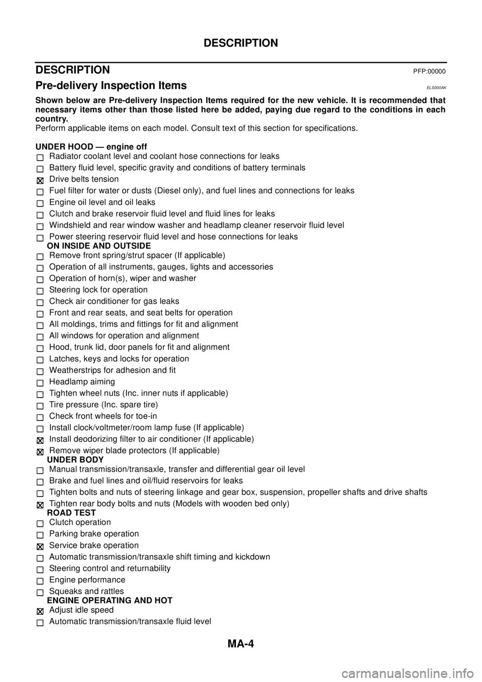
Shown below are Pre-delivery Inspection Items required for the new vehicle. It is recommended that
necessary items other than those listed here be added, paying due regard to the conditions in each
country.
Perform applicable items on each model. Consult text of this section for specifications.
UNDER HOOD — engine off
Radiator coolant level and coolant hose connections for leaks
Battery fluid level, specific gravity and conditions of battery terminals
Drive belts tension
Fuel filter for water or dusts (Diesel only), and fuel lines and connections for leaks
Engine oil level and oil leaks
Clutch and brake reservoir fluid level and fluid lines for leaks
Windshield and rear window washer and headlamp cleaner reservoir fluid level
Power steering reservoir fluid level and hose connections for leaks
ON INSIDE AND OUTSIDE
Remove front spring/strut spacer (If applicable)
Operation of all instruments, gauges, lights and accessories
Operation of horn(s), wiper and washer
Steering lock for operation
Check air conditioner for gas leaks
Front and rear seats, and seat belts for operation
All moldings, trims and fittings for fit and alignment
All windows for operation and alignment
Hood, trunk lid, door panels for fit and alignment
Latches, keys and locks for operation
Weatherstrips for adhesion and fit
Headlamp aiming
Tighten wheel nuts (Inc. inner nuts if applicable)
Tire pressure (Inc. spare tire)
Check front wheels for toe-in
Install clock/voltmeter/room lamp fuse (If applicable)
Install deodorizing filter to air conditioner (If applicable)
Remove wiper blade protectors (If applicable)
UNDER BODY
Manual transmission/transaxle, transfer and differential gear oil level
Brake and fuel lines and oil/fluid reservoirs for leaks
Tighten bolts and nuts of steering linkage and gear box, suspension, propeller shafts and drive shafts
Tighten rear body bolts and nuts (Models with wooden bed only)
ROAD TEST
Clutch operation
Parking brake operation
Service brake operation
Automatic transmission/transaxle shift timing and kickdown
Steering control and returnability
Engine performance
Squeaks and rattles
ENGINE OPERATING AND HOT
Adjust idle speed
Automatic transmission/transaxle fluid level
Page 2534 of 3066
MA-42
CHASSIS AND BODY MAINTENANCE
Drive Shaft
ELS000CL
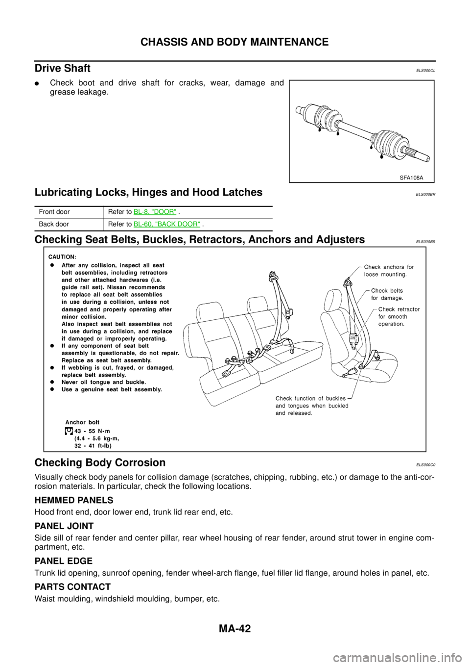
lCheck boot and drive shaft for cracks, wear, damage and
grease leakage.
Lubricating Locks, Hinges and Hood LatchesELS000BR
Checking Seat Belts, Buckles, Retractors, Anchors and AdjustersELS000BS
Checking Body CorrosionELS000C0
Visually check body panels for collision damage (scratches, chipping, rubbing, etc.) or damage to the anti-cor-
rosion materials. In particular, check the following locations.
HEMMED PANELS
Hood front end, door lower end, trunk lid rear end, etc.
PANEL JOINT
Side sill of rear fender and center pillar, rear wheel housing of rear fender, around strut tower in engine com-
partment, etc.
PANEL EDGE
Trunk lid opening, sunroof opening, fender wheel-arch flange, fuel filler lid flange, around holes in panel, etc.
PA R T S C O N TA C T
Waist moulding, windshield moulding, bumper, etc.
SFA108A
Front door Refer toBL-8, "DOOR".
Back door Refer toBL-60, "
BACK DOOR".
Page 2962 of 3066
SRS-40
DISPOSAL OF AIR BAG MODULE AND SEAT BELT PRE-TENSIONER
DISPOSAL OF AIR BAG MODULE AND SEAT BELT PRE-TENSIONER
PFP:00014
Caution for Air Bag Module and Seat Belt Pre-tensionerEHS000DE
lBefore disposing of air bag module and seat belt pre-tensioner, or vehicles equipped with such systems,
deploy the systems. If such systems have already been deployed due to an accident, dispose of them as
indicated in “SRS-45, "
DISPOSING OF AIR BAG MODULE AND SEAT BELT PRE-TENSIONER"
lWhen deploying the air bag module and seat belt pre-tensioner, always use the Special Service Tool;
Deployment tool (KV99106400).
lWhen deploying the air bag module and seat belt pre-tensioner, stand at least 5 m (16 ft) away from the
deployment component.
lWhen deploying air bag module and seat belt pre-tensioner, a fairly loud noise is made, followed by
smoke being released. The smoke is not poisonous, however, be careful not to inhale smoke since it irri-
tates the throat and can cause choking.
lAlways activate one air bag module at a time.
lDue to heat, leave air bag module unattended for more than 30 minutes after deployment. Also leave seat
belt pre-tensioner unattended for more than 10 minutes after deployment.
lBe sure to wear gloves when handling a deployed air bag module and seat belt pre-tensioner.
lNever apply water to the deployed air bag module and seat belt pre-tensioner.
lWash your hands clean after finishing work.
lPlace the vehicle outdoors with an open space of at least 6 m (20 ft) on all sides when deploying air bag
module and seat belt pre-tensioner while mounted in vehicle.
lUse a voltmeter to make sure the vehicle battery is fully charged.
lDo not dispose of the air bag module and seat belt pre-tensioner un-deployed.
CHECKING DEPLOYMENT TOOL
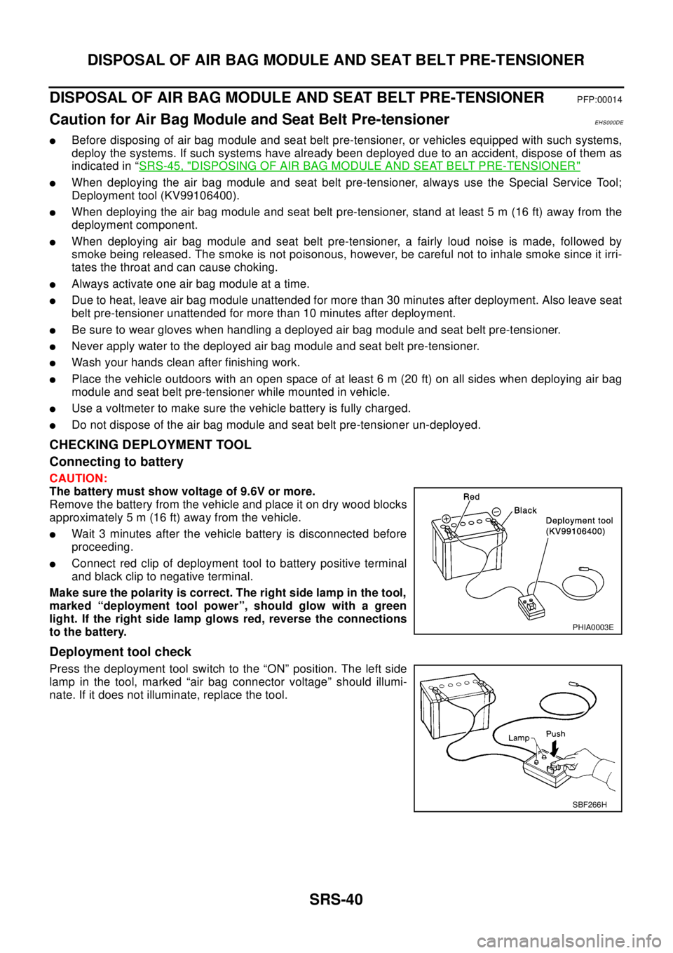
Connecting to battery
CAUTION:
The battery must show voltage of 9.6V or more.
Remove the battery from the vehicle and place it on dry wood blocks
approximately 5 m (16 ft) away from the vehicle.
lWait 3 minutes after the vehicle battery is disconnected before
proceeding.
lConnect red clip of deployment tool to battery positive terminal
and black clip to negative terminal.
Make sure the polarity is correct. The right side lamp in the tool,
marked “deployment tool power”, should glow with a green
light. If the right side lamp glows red, reverse the connections
to the battery.
Deployment tool check
Press the deployment tool switch to the “ON” position. The left side
lamp in the tool, marked “air bag connector voltage” should illumi-
nate. If it does not illuminate, replace the tool.
PHIA0003E
SBF266H