hood release NISSAN X-TRAIL 2003 Electronic Repair Manual
[x] Cancel search | Manufacturer: NISSAN, Model Year: 2003, Model line: X-TRAIL, Model: NISSAN X-TRAIL 2003Pages: 3066, PDF Size: 51.47 MB
Page 745 of 3066
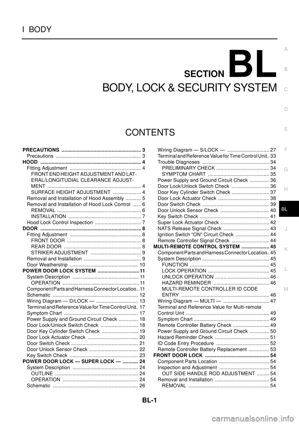
BL-1
BODY, LOCK & SECURITY SYSTEM
IBODY
CONTENTS
C
D
E
F
G
H
J
K
L
M
SECTION
A
B
BL
BODY, LOCK & SECURITY SYSTEM
PRECAUTIONS .......................................................... 3
Precautions .............................................................. 3
HOOD ......................................................................... 4
Fitting Adjustment .................................................... 4
FRONT END HEIGHT ADJUSTMENT AND LAT-
ERAL/LONGITUDIAL CLEARANCE ADJUST-
MENT .................................................................... 4
SURFACE HEIGHT ADJUSTMENT ..................... 4
Removal and Installation of Hood Assembly ............ 5
Removal and Installation of Hood Lock Control ....... 6
REMOVAL ............................................................. 6
INSTALLATION ..................................................... 7
Hood Lock Control Inspection .................................. 7
DOOR ......................................................................... 8
Fitting Adjustment .................................................... 8
FRONT DOOR ...................................................... 8
REAR DOOR ........................................................ 8
STRIKER ADJUSTMENT ..................................... 9
Removal and Installation .......................................... 9
Door Weatherstrip .................................................. 10
POWER DOOR LOCK SYSTEM ...............................11
System Description .................................................11
OPERATION ........................................................11
Component Parts and Harness Connector Location....11
Schematic .............................................................. 12
Wiring Diagram — D/LOCK — ............................... 13
Terminal and Reference Value for Time Control Unit... 17
Symptom Chart ...................................................... 17
Power Supply and Ground Circuit Check ............... 18
Door Lock/Unlock Switch Check ............................ 18
Door Key Cylinder Switch Check ........................... 19
Door Lock Actuator Check ..................................... 20
Door Switch Check ................................................. 21
Door Unlock Sensor Check .................................... 22
Key Switch Check .................................................. 23
POWER DOOR LOCK — SUPER LOCK — ............ 24
System Description ................................................ 24
OUTLINE ............................................................. 24
OPERATION ....................................................... 24
Schematic .............................................................. 26Wiring Diagram — S/LOCK — ............................... 27
Terminal and Reference Value for Time Control Unit... 33
Trouble Diagnoses ................................................. 34
PRELIMINARY CHECK ....................................... 34
SYMPTOM CHART ............................................. 35
Power Supply and Ground Circuit Check ............... 36
Door Lock/Unlock Switch Check ............................ 36
Door Key Cylinder Switch Check ............................ 37
Door Lock Actuator Check ...................................... 38
Door Switch Check ................................................. 39
Door Unlock Sensor Check .................................... 40
Key Switch Check ................................................... 41
Super Lock Actuator Check .................................... 42
NATS Release Signal Check .................................. 43
Ignition Switch “ON” Circuit Check ......................... 44
Remote Controller Signal Check ............................ 44
MULTI-REMOTE CONTROL SYSTEM ..................... 45
Component Parts and Harness Connector Location... 45
System Description ................................................. 45
FUNCTION .......................................................... 45
LOCK OPERATION ............................................. 45
UNLOCK OPERATION ........................................ 46
HAZARD REMINDER ......................................... 46
MULTI-REMOTE CONTROLLER ID CODE
ENTRY ................................................................ 46
Wiring Diagram — MULTI — .................................. 47
Terminal and Reference Value for Multi-remote
Control Unit ............................................................. 49
Symptom Chart ....................................................... 49
Remote Controller Battery Check ........................... 49
Power Supply and Ground Circuit Check ............... 50
Hazard Reminder Check ........................................ 51
ID Code Entry Procedure ....................................... 52
Remote Controller Battery Replacement ................ 53
FRONT DOOR LOCK ............................................... 54
Component Parts Location ..................................... 54
Inspection and Adjustment ..................................... 54
OUT SIDE HANDLE ROD ADJUSTMENT .......... 54
Removal and Installation ........................................ 54
REMOVAL ........................................................... 54
Page 749 of 3066
HOOD
BL-5
C
D
E
F
G
H
J
K
L
MA
B
BL
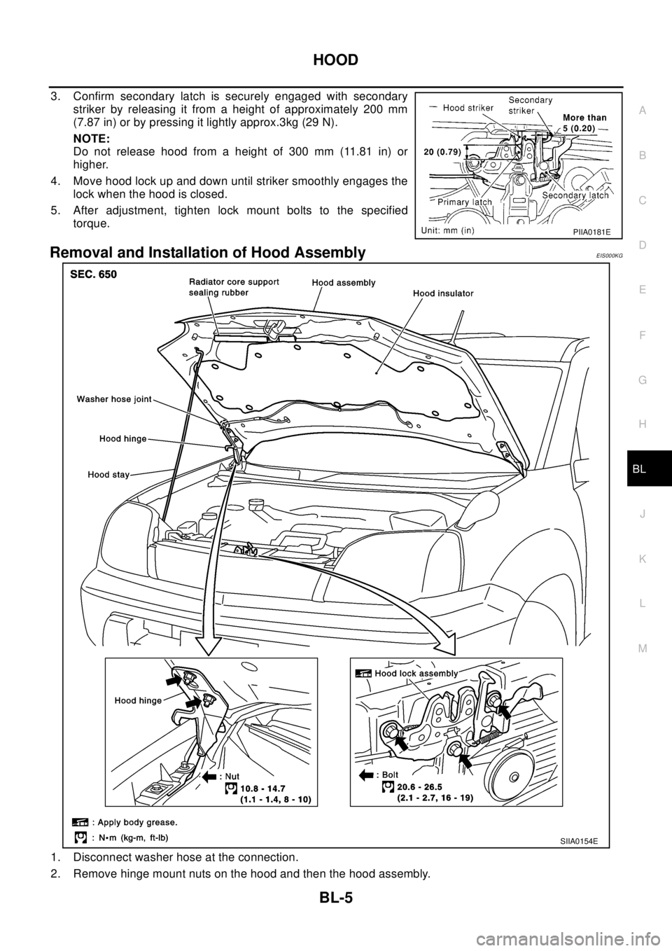
3. Confirm secondary latch is securely engaged with secondary
striker by releasing it from a height of approximately 200 mm
(7.87 in) or by pressing it lightly approx.3kg (29 N).
NOTE:
Do not release hood from a height of 300 mm (11.81 in) or
higher.
4. Move hood lock up and down until striker smoothly engages the
lock when the hood is closed.
5. After adjustment, tighten lock mount bolts to the specified
torque.
Removal and Installation of Hood AssemblyEIS000KG
1. Disconnect washer hose at the connection.
2. Remove hinge mount nuts on the hood and then the hood assembly.
PIIA0181E
SIIA0154E
Page 1343 of 3066
![NISSAN X-TRAIL 2003 Electronic Repair Manual DTC P0420 THREE WAY CATALYST FUNCTION
EC-229
[QR (WITH EURO-OBD)]
C
D
E
F
G
H
I
J
K
L
MA
EC
DTC P0420 THREE WAY CATALYST FUNCTIONPFP:20905
On Board Diagnosis LogicEBS00B6A
The ECM monitors the switchi NISSAN X-TRAIL 2003 Electronic Repair Manual DTC P0420 THREE WAY CATALYST FUNCTION
EC-229
[QR (WITH EURO-OBD)]
C
D
E
F
G
H
I
J
K
L
MA
EC
DTC P0420 THREE WAY CATALYST FUNCTIONPFP:20905
On Board Diagnosis LogicEBS00B6A
The ECM monitors the switchi](/img/5/57402/w960_57402-1342.png)
DTC P0420 THREE WAY CATALYST FUNCTION
EC-229
[QR (WITH EURO-OBD)]
C
D
E
F
G
H
I
J
K
L
MA
EC
DTC P0420 THREE WAY CATALYST FUNCTIONPFP:20905
On Board Diagnosis LogicEBS00B6A
The ECM monitors the switching frequency ratio of heated oxygen
sensors 1 and 2.
A three way catalyst (Manifold) with high oxygen storage capacity
will indicate a low switching frequency of heated oxygen sensor 2.
As oxygen storage capacity decreases, the heated oxygen sensor 2
switching frequency will increase.
When the frequency ratio of heated oxygen sensors 1 and 2
approaches a specified limit value, the three way catalyst (Manifold)
malfunction is diagnosed.
DTC Confirmation ProcedureEBS00B6B
NOTE:
If “DTC Confirmation Procedure” has been previously conducted, always turn ignition switch “OFF” and wait at
least 10 seconds before conducting the next test.
WITH CONSULT-II
TESTING CONDITION:
lOpen engine hood before conducting the following procedure.
lDo not hold engine speed for more than the specified minutes below.
1. Turn ignition switch “ON”.
2. Select “DTC & SRT CONFIRMATION” then “SRT WORK SUP-
PORT”modewithCONSULT-II.
3. Start engine.
4. Rev engine up to 2,000 to 3,000 rpm and hold it for 3 consecu-
tive minutes then release the accelerator pedal completely.
If "INCMP" of "CATALYST" changed to "COMPLT", go to step 7
5. Wait 5 seconds at idle.
PBIB0067E
DTC No. Trouble diagnosis name DTC detecting condition Possible cause
P0420
0420Catalyst system effi-
ciency below threshold
lThree way catalyst (Manifold) does not oper-
ate properly.
lThree way catalyst (Manifold) does not have
enough oxygen storage capacity.
lThree way catalyst (Manifold)
lExhaust tube
lIntake air leaks
lFuel injectors
lFuel injector leaks
lSpark plug
lImproper ignition timing
PBIB0566E
Page 2023 of 3066
![NISSAN X-TRAIL 2003 Electronic Repair Manual CYLINDER HEAD
EM-53
[QR20DE]
C
D
E
F
G
H
I
J
K
L
MA
EM
lIf some cylinders have low compression pressure, pour small amount of engine oil into the spark plug hole
of the cylinder to re-check it for com NISSAN X-TRAIL 2003 Electronic Repair Manual CYLINDER HEAD
EM-53
[QR20DE]
C
D
E
F
G
H
I
J
K
L
MA
EM
lIf some cylinders have low compression pressure, pour small amount of engine oil into the spark plug hole
of the cylinder to re-check it for com](/img/5/57402/w960_57402-2022.png)
CYLINDER HEAD
EM-53
[QR20DE]
C
D
E
F
G
H
I
J
K
L
MA
EM
lIf some cylinders have low compression pressure, pour small amount of engine oil into the spark plug hole
of the cylinder to re-check it for compression.
–If the added engine oil improves the compression, the piston rings may be worn out or damaged. Check
the piston rings and replace if necessary.
–If the compression pressure remains at low level despite the addition of engine oil, the valves may be mal-
functioning. Check the valves for damage. Replace the valve or valve seat accordingly.
lIf two adjacent cylinders have respectively low compression pressure and their compression remains low
even after the addition of engine oil, the gaskets are leaking. In such a case, replace the cylinder head
gaskets.
8. Install spark plug, ignition coil and harness connectors.
Removal and InstallationEBS009R4
REMOVAL
1. Release fuel pressure. Refer toEC-34, "FUEL PRESSURE RELEASE"(WITH EURO-OBD),EC-399,
"FUEL PRESSURE RELEASE"(WITHOUT EURO-OBD).
2. Drain engine coolant and engine oil.
3. Remove the following components and related parts.
lEngine hood and engine under cover.
lAir cleaner case and air duct assembly; Refer toEM-15, "Removal and Installation".
lIgnition coils; Refer toEM-27, "Removal and Installation".
lRocker cover; Refer toEM-31, "Removal and Installation".
lEngine Coolant reservoir tank
lAuxiliary drive belt; Refer toEM-14, "Removal and Installation of Auxiliary Drive Belt Auto- tensioner".
lAlternator
lAuxiliary drive belt auto -tensioner; Refer toEM-14, "Removal and Installation of Auxiliary Drive Belt Auto-
tensioner".
lExhaust front tube; Refer toEX-2, "EXHAUST SYSTEM".
lExhaust manifold; Refer toEM-22, "Removal and Installation".
lIntake manifold collector, intake manifold and fuel tube assembly; Refer toEM-17, "Removal and Installa-
tion".
lWater control valve and housing; Refer toCO-21, "THERMOSTAT AND WATER CONTROL VALVE".
4. Remove front cover and timing chain. Refer toEM-43, "
Removal and Installation".
KBIA0250E
1 Cylinder head assembly 2 Cylinder head gasket 3 Cylinder head bolt
Page 2032 of 3066
![NISSAN X-TRAIL 2003 Electronic Repair Manual EM-62
[QR20DE]
ENGINE ASSEMBLY
1. Release fuel pressure. Refer toEC-34, "FUEL PRESSURE RELEASE"(WITH EURO-OBD),EC-399,
"FUEL PRESSURE RELEASE"(WITHOUT EURO-OBD).
2. Remove engine hood.
3. Drain coolan NISSAN X-TRAIL 2003 Electronic Repair Manual EM-62
[QR20DE]
ENGINE ASSEMBLY
1. Release fuel pressure. Refer toEC-34, "FUEL PRESSURE RELEASE"(WITH EURO-OBD),EC-399,
"FUEL PRESSURE RELEASE"(WITHOUT EURO-OBD).
2. Remove engine hood.
3. Drain coolan](/img/5/57402/w960_57402-2031.png)
EM-62
[QR20DE]
ENGINE ASSEMBLY
1. Release fuel pressure. Refer toEC-34, "FUEL PRESSURE RELEASE"(WITH EURO-OBD),EC-399,
"FUEL PRESSURE RELEASE"(WITHOUT EURO-OBD).
2. Remove engine hood.
3. Drain coolant from radiator drain plug.
4. Remove the following parts.
lLH/RH under cover
lLH/RH Front wheel
lBattery
lAuxiliary drive belt; Refer toEM-14, "Removal and Installation of Auxiliary Drive Belt Auto- tensioner".
lAir duct and air cleaner case assembly; Refer toEM-15, "Removal and Installation".
lAlternator
lRadiator and radiator fan assembly; Refer toCO-12, "RADIATOR".
5. Disconnect engine room harness from the engine side and set it aside for easier work.
6. Disconnect all the body-side vacuum hoses and air hoses at engine side.
Engine room LH
7. Disconnect fuel hose, and plug it to prevent fuel from draining. Refer toEM-17, "
INTAKE MANIFOLD"
8. Disconnect heater hose, and install plug it to prevent engine coolant from draining.
9. Disconnect select cable from transaxle (A/T models).
10. Remove clutch operating cylinder from transaxle, and move it aside (M/T models).
11. Disconnect shift cable from transaxle (M/T models).
Engine room RH
12. Remove engine coolant reservoir tank.
13. Remove air conditioner compressor with piping connected from engine. Temporarily secure it on body
with a rope to avoid putting load on it.
Vehicle underbody
14. Remove exhaust front tube.
15. Remove propeller shaft.
16. Remove steering shaft from steering gear.
17. Disconnect power steering fluid cooler piping at a point between body and engine.
18. Remove ABS sensor from brake caliper.
19. Remove brake caliper with piping connected from steering knuckle. Temporarily secure it on body with a
rope to avoid load on it.
20. Remove LH/RH suspension from steering knuckle under strut.
Removal
21. Install engine slingers into front left of cylinder head and rear right of cylinder head.
lUse alternator bracket mounting bolt holes for the frontside.
22. Lift with hoist and secure the engine in position.Slinger bolts:
Front: 51.0 - 64.7 N·m (5.2 - 6.6 kg-m, 38 - 47 ft-lb)
Rear: 24.5 - 31.4 N·m (2.5 - 3.2 kg-m, 18 - 23 ft-lb)
KBIA0255E
Page 2273 of 3066
GI-20
HOW TO USE THIS MANUAL
lignition switch is “OFF”,
ldoors, hood and trunk lid/back door are closed,
lpedals are not depressed, and
lparking brake is released.
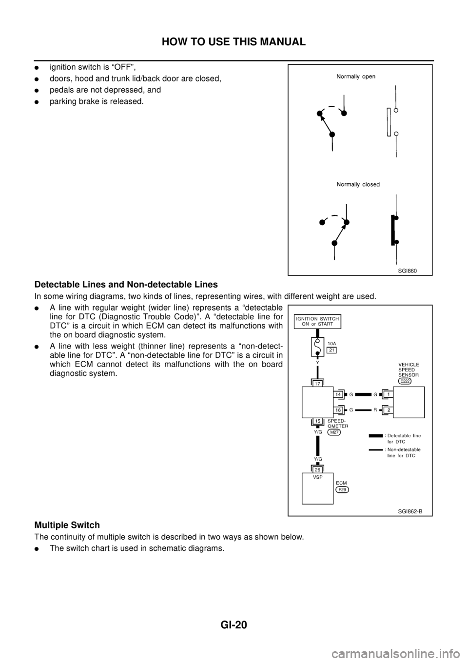
Detectable Lines and Non-detectable Lines
In some wiring diagrams, two kinds of lines, representing wires, with different weight are used.
lA line with regular weight (wider line) represents a “detectable
line for DTC (Diagnostic Trouble Code)”. A “detectable line for
DTC” is a circuit in which ECM can detect its malfunctions with
the on board diagnostic system.
lA line with less weight (thinner line) represents a “non-detect-
able line for DTC”. A “non-detectable line for DTC” is a circuit in
which ECM cannot detect its malfunctions with the on board
diagnostic system.
Multiple Switch
The continuity of multiple switch is described in two ways as shown below.
lThe switch chart is used in schematic diagrams.
SGI860
SGI862-B
Page 2362 of 3066
IDX-5
A
C
D
E
F
G
H
I
J
K
L B
IDX
ALPHABETICAL INDEX
Front washer ......................................................WW-4
Front wiper .........................................................WW-4
FTS - Wiring diagram ......................................EC-752
Fuel check valve ..............................................EC-372
Fuel cut control (at no load high engine speed)EC-28,
EC-393
,EC-662
Fuel filler lid ........................................................BL-64
Fuel filter ..........................................................EC-664
Fuel filter replacement(QR20DE) .........................FL-4
Fuel filter replacement(YD22DDTi) .......FL-15,MA-30
Fuel gauge ..................................................DI-4,DI-22
Fuel injection control system ...........................EC-660
Fuel injection system .........................EC-194,EC-200
Fuel injector .....................................................EC-727
Fuel injector adjustment resistor ......................EC-777
Fuel injector and fuel tube(QR20DE) ................EM-29
Fuel injector and fuel tube(YD22DDTi) ............EM-135
Fuel leak ..........................................................EC-781
Fuel line inspection(QR20DE) .................FL-3,MA-23
Fuel line inspection(YD22DDTi) ............FL-14,MA-30
Fuel pressure check ............................EC-34,EC-399
Fuel pressure release ..........................EC-34,EC-399
Fuel pressure relief valve ................................EC-665
Fuel pump ..........................................EC-352,EC-627
Fuel pump and gauge(QR20DE) ..........................FL-4
Fuel system(QR20DE) .........................................FL-3
Fuel system(YD22DDTi) .....................................FL-14
Fuel tank(QR20DE) ..............................................FL-9
Fuel tank(YD22DDTi) .........................................FL-21
Fuel temperature sensor .................................EC-751
Fuse ...................................................................PG-12
Fuse and fusible link box ...................................PG-77
Fusible link .........................................................PG-12
G
Gear components (M/T) .......................MT-19
,MT-24
Generator ..........................................................SC-12
Generator - See Alternator ................................SC-12
Generic scan tool (GST) ....................................EC-96
Glass ..................................................GW-41,GW-43
GLOW - Wiring diagram ..................................EC-797
Glow plug .........................................................EC-796
Glow plug(YD22DDTi) .....................................EM-130
Glow relay ........................................................EC-796
Grease ...............................................................MA-17
Grille - See Exterior .............................................EI-11
Ground distribution ............................................PG-13
G-sensor .............................................................TF-50
H
H/AIM - Wiring diagram ......................................LT-15
H/LAMP - Wiring diagram ...........................LT-4,LT-5
H/MIRROR - Wiring diagram ............................GW-10
Harness connector ............................................PG-70
Harness layout ...................................................PG-29
Headlamp .............................................................LT-4
Headlamp aiming control ....................................LT-15
Headlamp leveler - See Headlamp aiming control .......
LT-15
Headlamp washer ............................................WW-19
Headlining - See Roof trim ..................................EI-29
Heated oxygen sensor 1 ....EC-160,EC-166,EC-174,
EC-284
,EC-290,EC-490,EC-581
Heated oxygen sensor 1 heater .........EC-120,EC-568
Heated oxygen sensor 2 ....EC-181,EC-187,EC-296,
EC-303
,EC-587
Heated oxygen sensor 2 heater .........EC-125,EC-573
Heated seat ...............................................SE-3,SE-5
HEATER - Wiring diagram ................................MTC-6
Heater and cooling unit (Heater core) ............ATC-115
Heater mirror .....................................................GW-10
Heater system - Wiring diagram .......................MTC-6
Heater unit (heater core) ..ATC-120,MTC-23,MTC-26
HFC134a (R134a) system precaution ...............ATC-4
HFC134a (R134a) system service procedureATC-123
HFC134a (R134a) system service tools ..........ATC-12
HFC134a system service equipment precautionATC-8
HO2S1 - Wiring diaram ......EC-122,EC-162,EC-169,
EC-177
,EC-492
HO2S2 - Wiring diagram ....EC-183,EC-190,EC-299,
EC-306
HO2S2H - Wiring diagram ...............................EC-127
Hood ....................................................................BL-4
Horn .................................................................WW-23
HORN - Wiring diagram ...................................WW-23
How to erase DTC ...........................................EC-666
HowtoeraseDTCforOBDsystem .....EC-46,EC-402
I
IATS - Wiring diagram .....................................EC-138
IATSEN - Wiring diagram ................................EC-578
Identification .....................................................ATC-10
Idle air volume learning ........................EC-31,EC-396
Idle speed .............................EC-64,EC-412,EC-672
IGN/SG - Wiring diagram .................................EC-335
Ignition coil .........................................EC-334,EC-592
Ignition coil(QR20DE) .......................................EM-27
Ignition control system .......................EC-334,EC-592
Ignition timing .......................................EC-64,EC-412
IGNSYS - Wiring diagram ................................EC-593
ILL - Wiring diagram ...........................................LT-45
Illumination ..........................................................LT-45
In vehicle sensor ...............ATC-95,ATC-97,ATC-106
INJECT - Wiring diagram ....EC-344,EC-619,EC-730
Injection nozzle(YD22DDTi) ...........................EM-135
Injector ...............................................EC-343,EC-618
Input shaft (FF M/T) ..............................MT-19,MT-24
Instrument panel ...................................................IP-3
INT/L - Wiring diagram ........................................LT-65
Intake air temparature sensor ............EC-136,EC-577
Intake door control linkage adjustment ............ATC-66
Intake door motorATC-64,ATC-112,MTC-10,MTC-22
Intake manifold(QR20DE) .................................EM-17
Page 2498 of 3066
MA-6
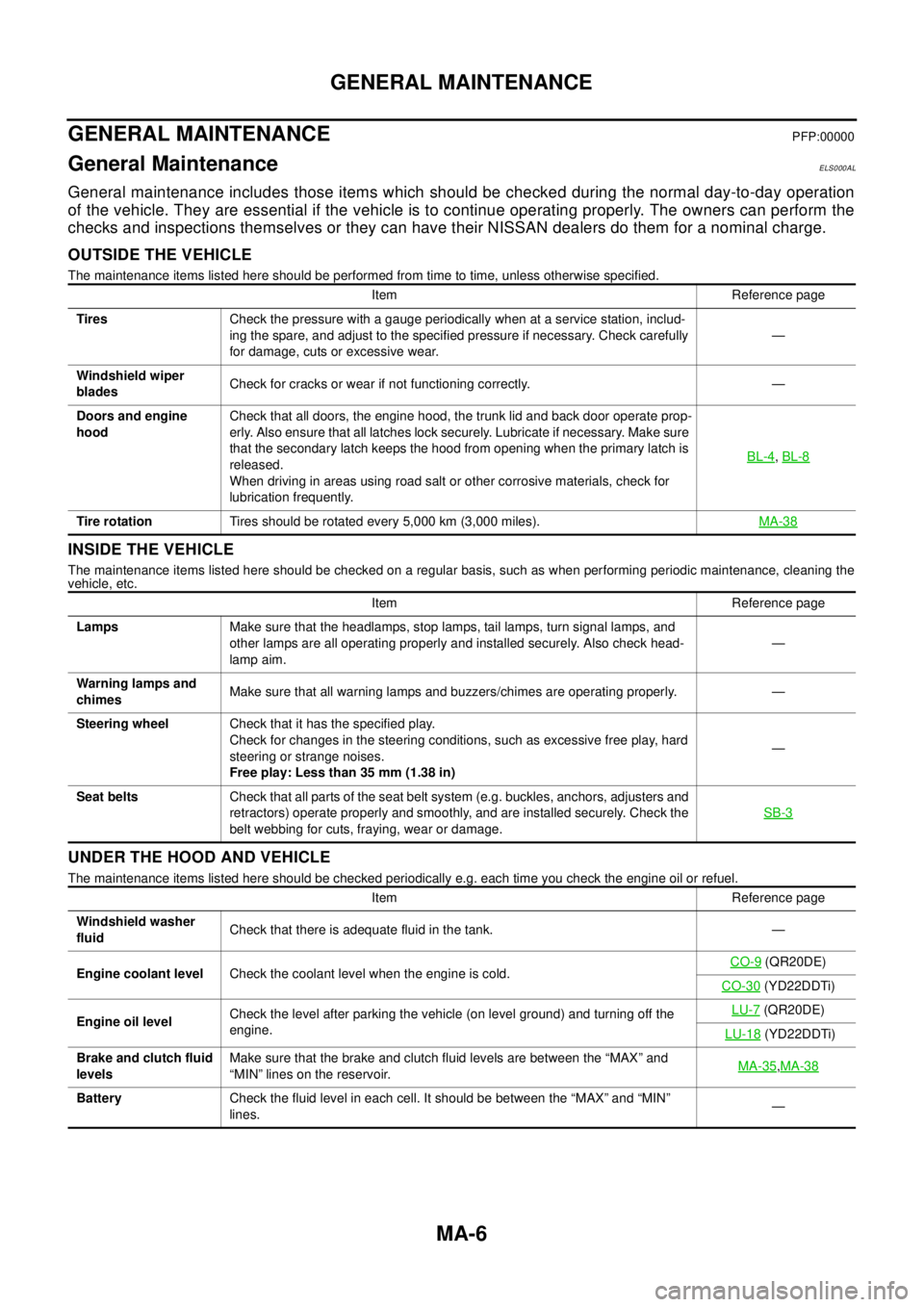
GENERAL MAINTENANCE
GENERAL MAINTENANCE
PFP:00000
General MaintenanceELS000AL
General maintenance includes those items which should be checked during the normal day-to-day operation
of the vehicle. They are essential if the vehicle is to continue operating properly. The owners can perform the
checks and inspections themselves or they can have their NISSAN dealers do them for a nominal charge.
OUTSIDE THE VEHICLE
The maintenance items listed here should be performed from time to time, unless otherwise specified.
INSIDE THE VEHICLE
The maintenance items listed here should be checked on a regular basis, such as when performing periodic maintenance, cleaning the
vehicle, etc.
UNDER THE HOOD AND VEHICLE
The maintenance items listed here should be checked periodically e.g. each time you check the engine oil or refuel.Item Reference page
TiresCheck the pressure with a gauge periodically when at a service station, includ-
ing the spare, and adjust to the specified pressure if necessary. Check carefully
for damage, cuts or excessive wear.—
Windshield wiper
bladesCheck for cracks or wear if not functioning correctly. —
Doors and engine
hoodCheck that all doors, the engine hood, the trunk lid and back door operate prop-
erly. Also ensure that all latches lock securely. Lubricate if necessary. Make sure
that the secondary latch keeps the hood from opening when the primary latch is
released.
When driving in areas using road salt or other corrosive materials, check for
lubrication frequently.BL-4
,BL-8
Tire rotationTires should be rotated every 5,000 km (3,000 miles).MA-38
Item Reference page
LampsMake sure that the headlamps, stop lamps, tail lamps, turn signal lamps, and
other lamps are all operating properly and installed securely. Also check head-
lamp aim.—
Warning lamps and
chimesMake sure that all warning lamps and buzzers/chimes are operating properly. —
Steering wheelCheck that it has the specified play.
Check for changes in the steering conditions, such as excessive free play, hard
steering or strange noises.
Free play: Less than 35 mm (1.38 in)—
Seat beltsCheck that all parts of the seat belt system (e.g. buckles, anchors, adjusters and
retractors) operate properly and smoothly, and are installed securely. Check the
belt webbing for cuts, fraying, wear or damage.SB-3
Item Reference page
Windshield washer
fluidCheck that there is adequate fluid in the tank. —
Engine coolant levelCheck the coolant level when the engine is cold.CO-9
(QR20DE)
CO-30
(YD22DDTi)
Engine oil levelCheck the level after parking the vehicle (on level ground) and turning off the
engine.LU-7
(QR20DE)
LU-18
(YD22DDTi)
Brake and clutch fluid
levelsMake sure that the brake and clutch fluid levels are between the “MAX” and
“MIN” lines on the reservoir.MA-35
,MA-38
BatteryCheck the fluid level in each cell. It should be between the “MAX” and “MIN”
lines.—