NISSAN X-TRAIL 2003 Service Repair Manual
X-TRAIL 2003
NISSAN
NISSAN
https://www.carmanualsonline.info/img/5/57404/w960_57404-0.png
NISSAN X-TRAIL 2003 Service Repair Manual
Trending: odometer, fuel pressure, air suspension, window, service interval, tire size, ignition
Page 3691 of 4179
COMBINATION METERS
DI-13
C
D
E
F
G
H
I
J
L
MA
B
DI
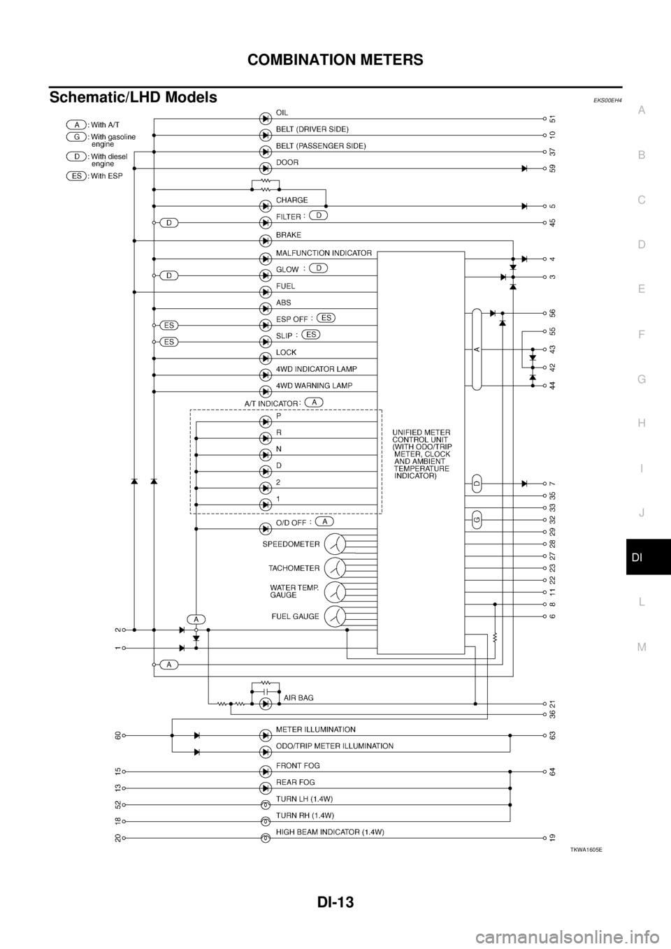
Schematic/LHD ModelsEKS00EH4
TKWA1605E
Page 3692 of 4179
DI-14
COMBINATION METERS
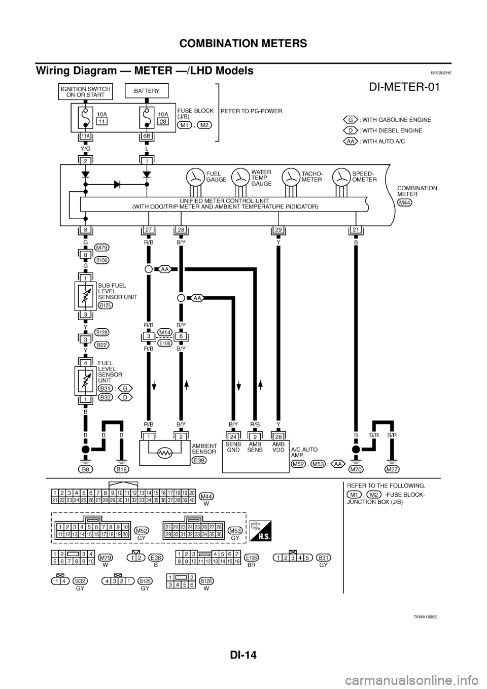
Wiring Diagram — METER —/LHD ModelsEKS00EH5
TKWA1606E
Page 3693 of 4179
COMBINATION METERS
DI-15
C
D
E
F
G
H
I
J
L
MA
B
DI
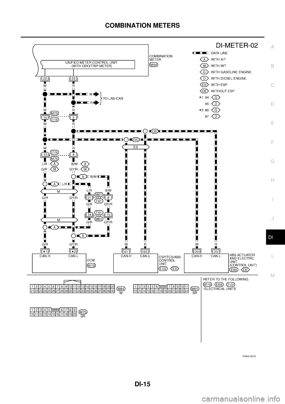
TKWA1607E
Page 3694 of 4179
DI-16
COMBINATION METERS
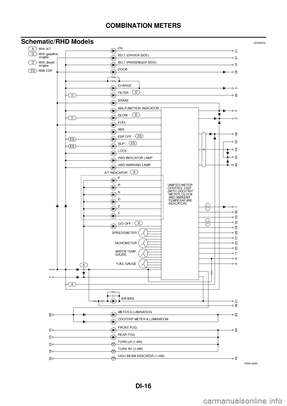
Schematic/RHD ModelsEKS00EHL
TKWA1608E
Page 3695 of 4179
COMBINATION METERS
DI-17
C
D
E
F
G
H
I
J
L
MA
B
DI
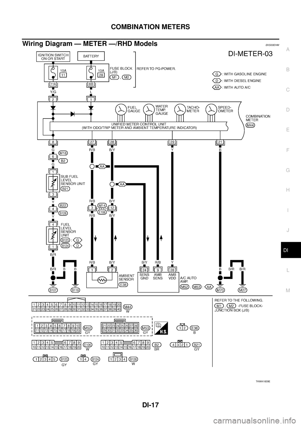
Wiring Diagram — METER —/RHD ModelsEKS00EHM
TKWA1609E
Page 3696 of 4179
DI-18
COMBINATION METERS
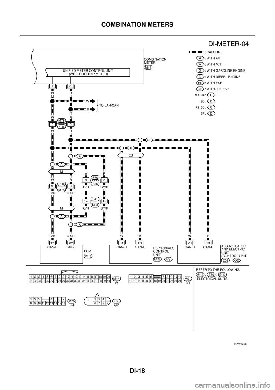
TKWA1610E
Page 3697 of 4179
COMBINATION METERS
DI-19
C
D
E
F
G
H
I
J
L
MA
B
DI
Terminals and Reference Value for Combination MeterEKS00EH6
NOTE:
*1:With auto A/C
Meter/Gauges Operation and Odo/Trip MeterEKS00EH7
SELF-DIAGNOSIS FUNCTION
�Odo/trip meter segment operation can be checked in self-diagnosis mode.
�Meters/gauges can be checked in self-diagnosis mode.
HOW TO ALTERNATE DIAGNOSIS MODE
1. Turn the ignition switch ON, and switch the odo/trip meter to “trip A” or “trip B”.
NOTE:
If the diagnosis function is activated with the trip meter A displayed, the mileage on the trip meter A will
indicate 0.0 miles, but the actual trip mileage will be retained. (Trip B operates the same way.)
2. Turn ignition switch OFF.
3. While pushing the odo/trip meter switch, turn ignition switch ON again.
4. Make sure that the trip meter displays “0.0”.
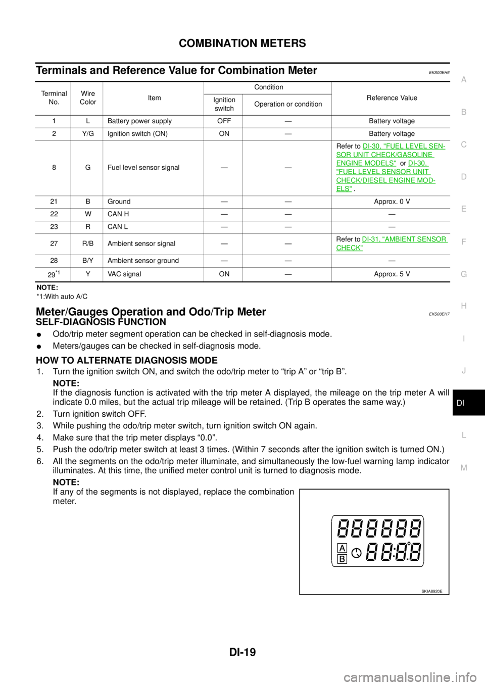
5. Push the odo/trip meter switch at least 3 times. (Within 7 seconds after the ignition switch is turned ON.)
6. All the segments on the odo/trip meter illuminate, and simultaneously the low-fuel warning lamp indicator
illuminates. At this time, the unified meter control unit is turned to diagnosis mode.
NOTE:
If any of the segments is not displayed, replace the combination
meter.
Terminal
No.Wire
ColorItemCondition
Reference Value
Ignition
switchOperation or condition
1 L Battery power supply OFF — Battery voltage
2 Y/G Ignition switch (ON) ON — Battery voltage
8 G Fuel level sensor signal — —Refer to DI-30, "
FUEL LEVEL SEN-
SOR UNIT CHECK/GASOLINE
ENGINE MODELS" or DI-30,
"FUEL LEVEL SENSOR UNIT
CHECK/DIESEL ENGINE MOD-
ELS" .
21 B Ground — — Approx. 0 V
22 W CAN H — — —
23 R CAN L — — —
27 R/B Ambient sensor signal — —Refer to DI-31, "
AMBIENT SENSOR
CHECK"
28 B/Y Ambient sensor ground — — —
29
*1Y VAC signal ON — Approx. 5 V
SKIA8920E
Page 3698 of 4179
DI-20
COMBINATION METERS
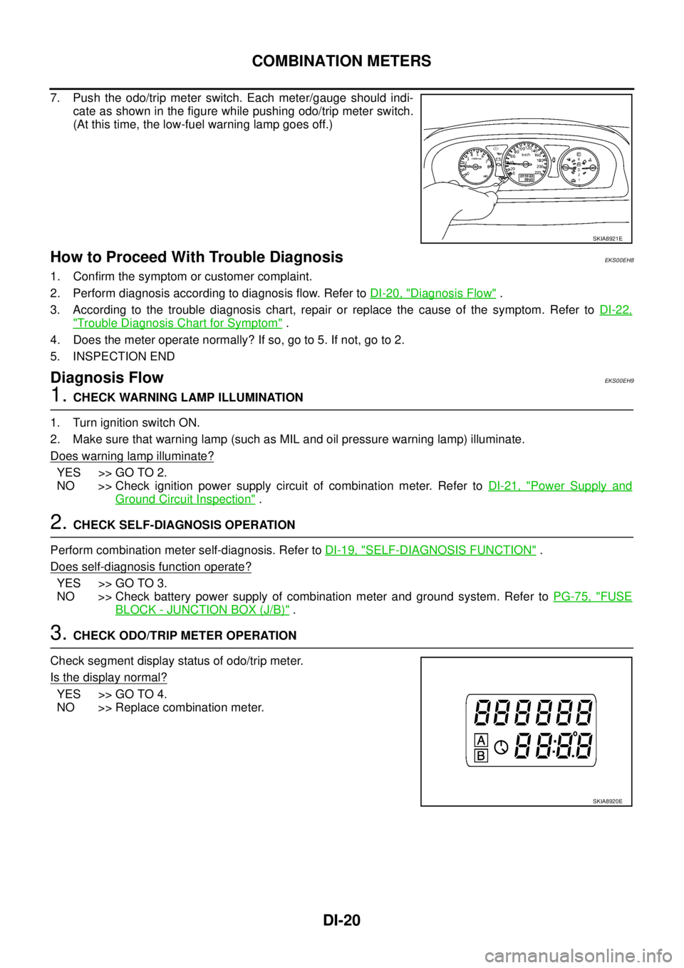
7. Push the odo/trip meter switch. Each meter/gauge should indi-
cate as shown in the figure while pushing odo/trip meter switch.
(At this time, the low-fuel warning lamp goes off.)
How to Proceed With Trouble DiagnosisEKS00EH8
1. Confirm the symptom or customer complaint.
2. Perform diagnosis according to diagnosis flow. Refer to DI-20, "
Diagnosis Flow" .
3. According to the trouble diagnosis chart, repair or replace the cause of the symptom. Refer to DI-22,
"Trouble Diagnosis Chart for Symptom" .
4. Does the meter operate normally? If so, go to 5. If not, go to 2.
5. INSPECTION END
Diagnosis FlowEKS00EH9
1. CHECK WARNING LAMP ILLUMINATION
1. Turn ignition switch ON.
2. Make sure that warning lamp (such as MIL and oil pressure warning lamp) illuminate.
Does warning lamp illuminate?
YES >> GO TO 2.
NO >> Check ignition power supply circuit of combination meter. Refer to DI-21, "
Power Supply and
Ground Circuit Inspection" .
2. CHECK SELF-DIAGNOSIS OPERATION
Perform combination meter self-diagnosis. Refer to DI-19, "
SELF-DIAGNOSIS FUNCTION" .
Does self-diagnosis function operate?
YES >> GO TO 3.
NO >> Check battery power supply of combination meter and ground system. Refer to PG-75, "
FUSE
BLOCK - JUNCTION BOX (J/B)" .
3. CHECK ODO/TRIP METER OPERATION
Check segment display status of odo/trip meter.
Is the display normal?
YES >> GO TO 4.
NO >> Replace combination meter.
SKIA8921E
SKIA8920E
Page 3699 of 4179
COMBINATION METERS
DI-21
C
D
E
F
G
H
I
J
L
MA
B
DI
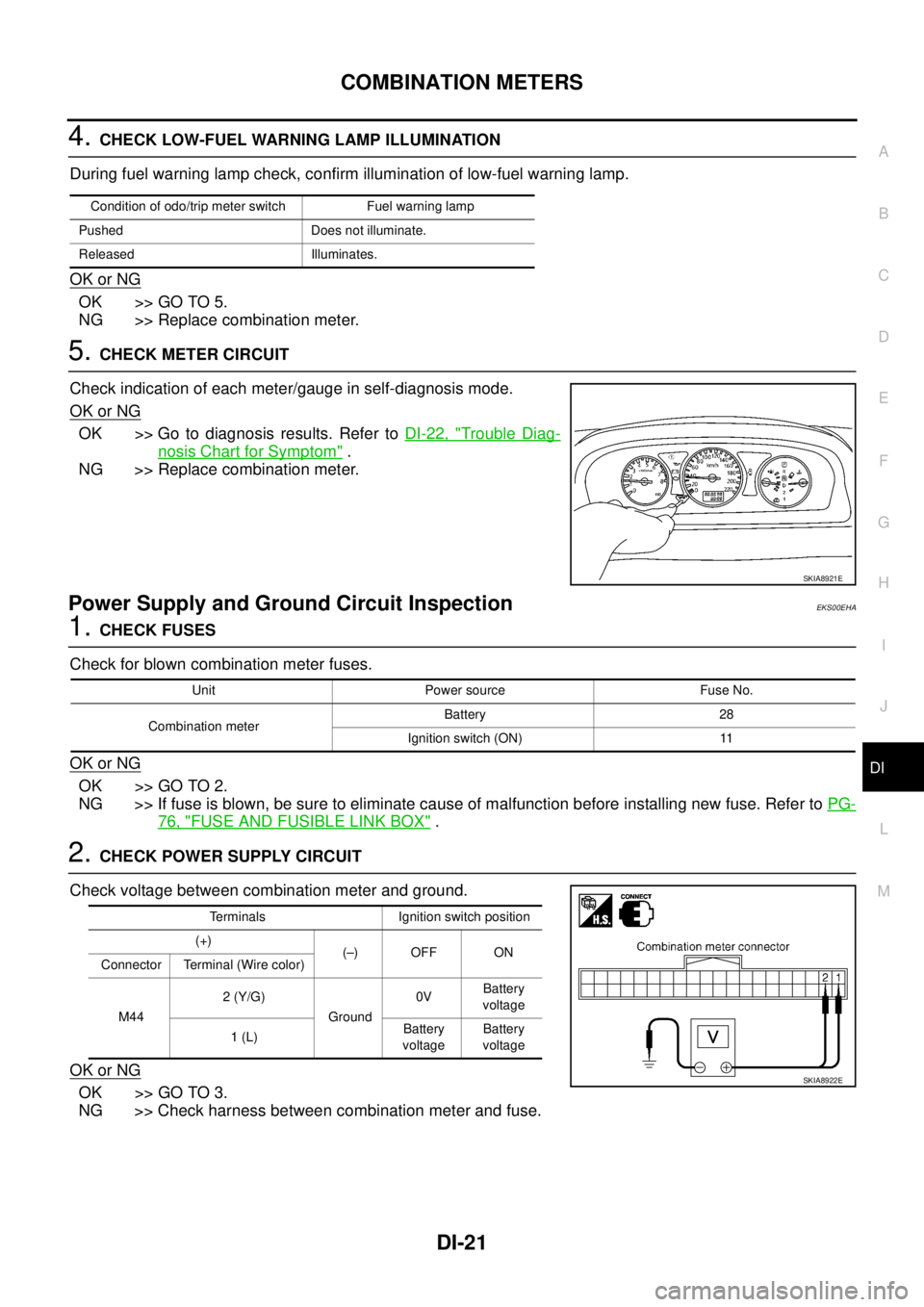
4. CHECK LOW-FUEL WARNING LAMP ILLUMINATION
During fuel warning lamp check, confirm illumination of low-fuel warning lamp.
OK or NG
OK >> GO TO 5.
NG >> Replace combination meter.
5. CHECK METER CIRCUIT
Check indication of each meter/gauge in self-diagnosis mode.
OK or NG
OK >> Go to diagnosis results. Refer to DI-22, "Trouble Diag-
nosis Chart for Symptom" .
NG >> Replace combination meter.
Power Supply and Ground Circuit InspectionEKS00EHA
1. CHECK FUSES
Check for blown combination meter fuses.
OK or NG
OK >> GO TO 2.
NG >> If fuse is blown, be sure to eliminate cause of malfunction before installing new fuse. Refer to PG-
76, "FUSE AND FUSIBLE LINK BOX" .
2. CHECK POWER SUPPLY CIRCUIT
Check voltage between combination meter and ground.
OK or NG
OK >> GO TO 3.
NG >> Check harness between combination meter and fuse.
Condition of odo/trip meter switch Fuel warning lamp
Pushed Does not illuminate.
Released Illuminates.
SKIA8921E
Unit Power source Fuse No.
Combination meterBattery 28
Ignition switch (ON) 11
Terminals Ignition switch position
(+)
(–) OFF ON
Connector Terminal (Wire color)
M442 (Y/G)
Ground0VBattery
voltage
1 (L)Battery
voltageBattery
voltage
SKIA8922E
Page 3700 of 4179
DI-22
COMBINATION METERS
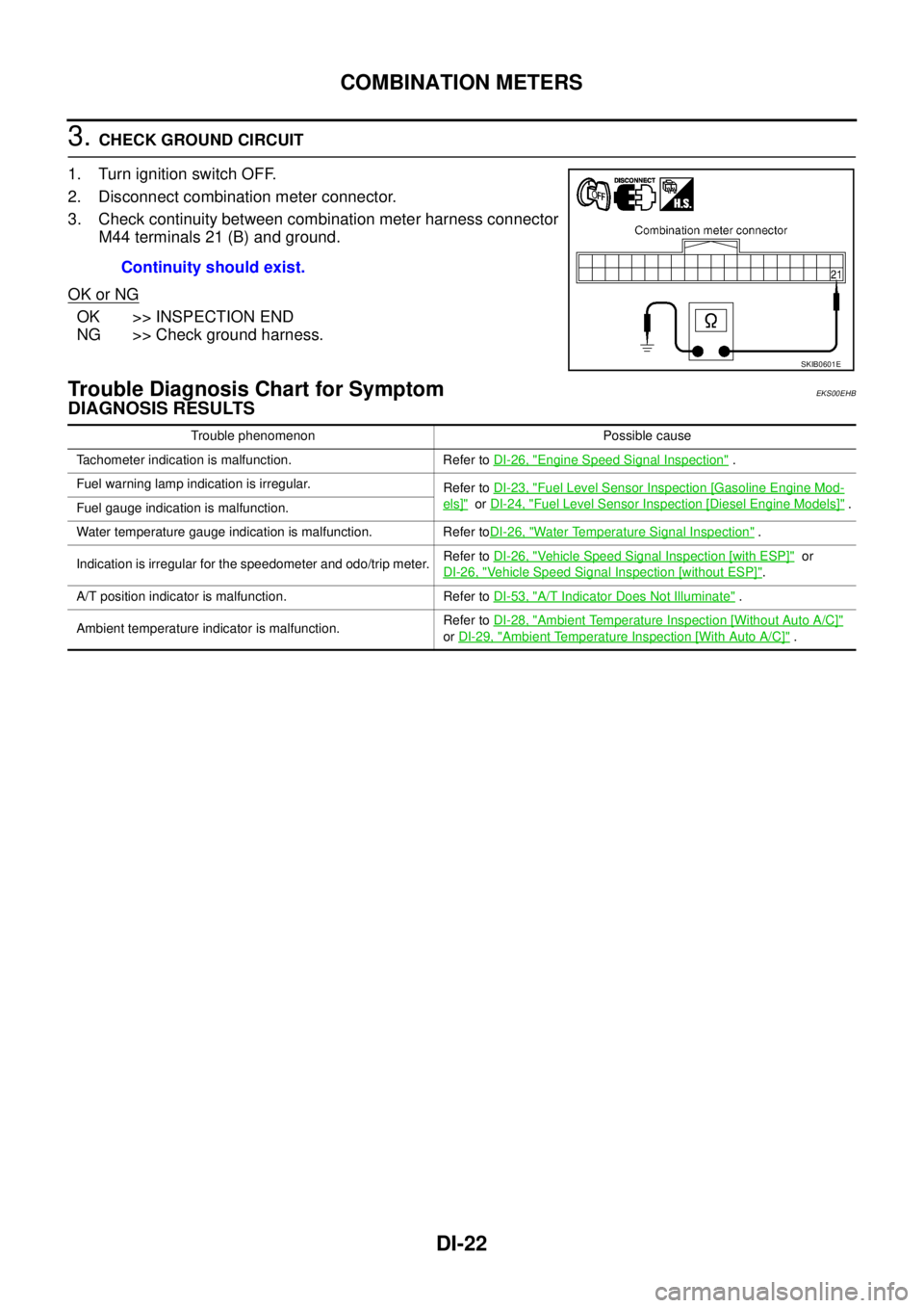
3. CHECK GROUND CIRCUIT
1. Turn ignition switch OFF.
2. Disconnect combination meter connector.
3. Check continuity between combination meter harness connector
M44 terminals 21 (B) and ground.
OK or NG
OK >> INSPECTION END
NG >> Check ground harness.
Trouble Diagnosis Chart for SymptomEKS00EHB
DIAGNOSIS RESULTS
Continuity should exist.
SKIB0601E
Trouble phenomenon Possible cause
Tachometer indication is malfunction. Refer to DI-26, "
Engine Speed Signal Inspection" .
Fuel warning lamp indication is irregular.
Refer to DI-23, "
Fuel Level Sensor Inspection [Gasoline Engine Mod-
els]" or DI-24, "Fuel Level Sensor Inspection [Diesel Engine Models]" .
Fuel gauge indication is malfunction.
Water temperature gauge indication is malfunction. Refer toDI-26, "
Water Temperature Signal Inspection" .
Indication is irregular for the speedometer and odo/trip meter.Refer to DI-26, "
Vehicle Speed Signal Inspection [with ESP]" or
DI-26, "
Vehicle Speed Signal Inspection [without ESP]".
A/T position indicator is malfunction. Refer to DI-53, "
A/T Indicator Does Not Illuminate" .
Ambient temperature indicator is malfunction.Refer to DI-28, "
Ambient Temperature Inspection [Without Auto A/C]"
or DI-29, "
Ambient Temperature Inspection [With Auto A/C]" .
Trending: CD player, air suspension, drain bolt, tire type, radio antenna, CO-11, four wheel drive
