sensor OPEL FRONTERA 1998 Owners Manual
[x] Cancel search | Manufacturer: OPEL, Model Year: 1998, Model line: FRONTERA, Model: OPEL FRONTERA 1998Pages: 6000, PDF Size: 97 MB
Page 875 of 6000

5B–3 ANTI–LOCK BRAKE SYSTEM
G-Sensor
Removal
350RX001
1. Remove center console.
Refer to Consoles in Body and Accessories
section.
2. Remove clip from G-sensor connector (1), then
disconnect connector.
3. Remove G-sensor assembly fixing bolt (2).
4. Remove G-sensor assembly (3).
Inspection and Repair
Refer to Chart B-5 in Brake Control System section.
Installation
1. Install G-sensor assembly (3).
Care should be taken so that the G-sensor is not
installed in the wrong direction.
2. Install G-sensor assembly fixing bolt (2).
Tighten the fixing bolt to the specified torque.
Torque : 10 Nꞏm (1.0kgꞏm/87 lb in)
3. Install G-sensor wiring connector (1).
4. Install center console.
Refer to Consoles in Body and Accessories
section.
Page 876 of 6000

5B–4ANTI–LOCK BRAKE SYSTEM
Front Wheel Speed Sensor
Front Wheel Speed Sensor and Associated Parts
350RW012
Legend
(1) Speed Sensor Connector
(2) Sensor Cable Fixing Bolt (Upper side)(3) Sensor Cable Fixing Bolt (Lower side)
(4) Sensor Cable Fixing Bolt (Sensor side)
(5) Speed Sensor
Removal
1. Remove speed sensor connector.
2. Remove sensor cable fixing bolt (Upper side).
3. Remove sensor cable fixing bolt (Lower side).
4. Remove the speed sensor cable fixing bolts (1) and
caliper fixing bolt (2) from caliper side speed sensor
cable bracket (3).
350RW010
5. Remove speed sensor.
Page 877 of 6000

5B–5 ANTI–LOCK BRAKE SYSTEM
Inspection and Repair
1. Check the speed sensor pole piece for presence of
foreign materials; remove any dirt, etc.
2. Check the pole piece for damage; replace speed
sensor if necessary.
3. Check the speed sensor cable for short or open
circuit, and replace with a new one if necessary.
To check for cable short or open, bend or stretch the
cable while checking for continuity.
4. Check the sensor ring for damage including tooth
chipping, and if damaged, replace the sensor ring
assembly. Refer to Front Hub and Disc in Drive Shaft
System section.
Installation
1. Install speed sensor and take care not to hit the speed
sensor pole piece during installation.
2. Install speed sensor fixing bolt and tighten the fixing
bolt to the specified torque.
Torque
Sensor side : 8 Nꞏm (0.8kgꞏm/69 lb in)
Caliper side : 155 Nꞏm (15.8kgꞏm/115 lb ft)
350RW011
Legend
(1) Caliper Fixing Bolt
(2) Bracket
(3) Sensor Fixing Bolt
(4) Sensor
(5) Knuckle
(6) Brake Caliper
3. Install speed sensor cable fixing bolt (Lower side) and
tighten the fixing bolt to the specified torque.
Torque : 24 Nꞏm (2.4kgꞏm/18 lb ft)
4. Install speed sensor cable fixing bolt (Upper side) and
tighten the fixing bolt to the specified torque.
Torque : 6 Nꞏm (0.6kgꞏm/52 lb in)NOTE: Confirm that a white line marked on the cable is
not twisted when connecting the speed sensor cable.
5. Install speed sensor connector.
Page 878 of 6000

5B–6ANTI–LOCK BRAKE SYSTEM
Rear Wheel Speed Sensor
Rear Wheel Speed Sensor and Associated Parts
350RW008
Legend
(1) Speed Sensor Connector
(2) Sensor Cable Fixing Bolt(3) Clip (11 pieces)
(4) Speed Sensor
(5) Sensor Fixing Bolt
Removal
1. Remove speed sensor connector.
2. Remove clip.
3. Remove sensor cable fixing bolt.
4. Remove sensor fixing bolt.
5. Remove speed sensor.
350RS035
Inspection and Repair
1. Check the speed sensor pole piece for presence of
foreign materials; remove any dirt, etc.2. Check the pole piece for damage, and replace the
speed sensor if necessary.
3. Check the speed sensor cable for a short or an open,
and replace with a new one if necessary. To check for
cable short or open, bend or stretch the cable while
checking for continuity.
4. Check the sensor ring for damage including tooth
chipping. If damaged replace the axle shaft assembly.
Refer to Front Hub and Disc in Drive Shaft System
section.
Installation
1. Install the speed sensor and take care not to hit the
speed sensor pole piece during installation.
2. Install the sensor fixing bolt and tighten it to the
specified torque.
Torque : 18 Nꞏm (1.8kgꞏm/13 lb ft)
3. Install the sensor cable fixing bolt and tighten it to the
specified torque.
Torque : 24 Nꞏm (2.4kgꞏm/18 lb ft)
NOTE: Confirm that the cable is not twisted when
connecting the speed sensor cable.
4. Install clip.
5. Install speed sensor connector.
Page 962 of 6000
6A–6
ENGINE MECHANICAL
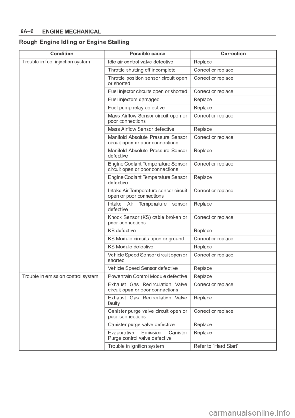
Rough Engine Idling or Engine Stalling
ConditionPossible causeCorrection
Trouble in fuel injection systemIdle air control valve defectiveReplace
Throttle shutting off incompleteCorrect or replace
Throttle position sensor circuit open
or shortedCorrect or replace
Fuel injector circuits open or shortedCorrect or replace
Fuel injectors damagedReplace
Fuel pump relay defectiveReplace
Mass Airflow Sensor circuit open or
poor connectionsCorrect or replace
Mass Airflow Sensor defectiveReplace
Manifold Absolute Pressure Sensor
circuit open or poor connectionsCorrect or replace
Manifold Absolute Pressure Sensor
defectiveReplace
Engine Coolant Temperature Sensor
circuit open or poor connectionsCorrect or replace
Engine Coolant Temperature Sensor
defectiveReplace
Intake Air Temperature sensor circuit
open or poor connectionsCorrect or replace
Intake Air Temperature sensor
defectiveReplace
Knock Sensor (KS) cable broken or
poor connectionsCorrect or replace
KS defectiveReplace
KS Module circuits open or groundCorrect or replace
KS Module defectiveReplace
Vehicle Speed Sensor circuit open or
shortedCorrect or replace
Vehicle Speed Sensor defectiveReplace
Trouble in emission control systemPowertrain Control Module defectiveReplace
Exhaust Gas Recirculation Valve
circuit open or poor connectionsCorrect or replace
Exhaust Gas Recirculation Valve
faultyReplace
Canister purge valve circuit open or
poor connectionsCorrect or replace
Canister purge valve defectiveReplace
Evaporative Emission Canister
Purge control valve defectiveReplace
Trouble in ignition systemRefer to “Hard Start”
Page 963 of 6000
6A–7
ENGINE MECHANICAL
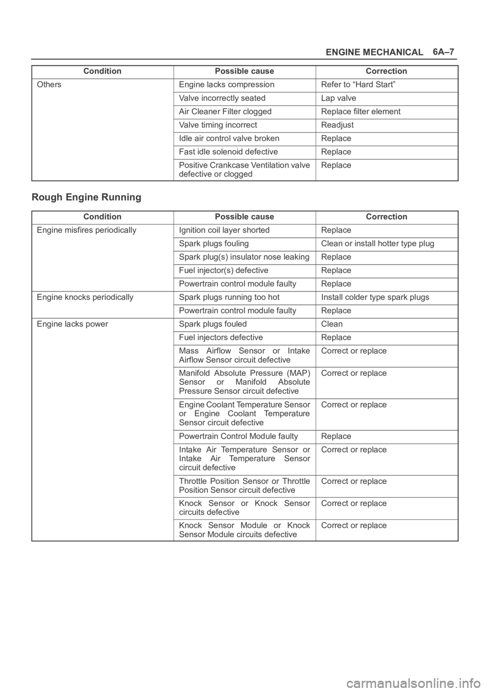
Condition CorrectionPossible cause
OthersEngine lacks compressionRefer to “Hard Start”
Valve incorrectly seatedLap valve
Air Cleaner Filter cloggedReplace filter element
Valve timing incorrectReadjust
Idle air control valve brokenReplace
Fast idle solenoid defectiveReplace
Positive Crankcase Ventilation valve
defective or cloggedReplace
Rough Engine Running
ConditionPossible causeCorrection
Engine misfires periodicallyIgnition coil layer shortedReplace
Spark plugs foulingClean or install hotter type plug
Spark plug(s) insulator nose leakingReplace
Fuel injector(s) defectiveReplace
Powertrain control module faultyReplace
Engine knocks periodicallySpark plugs running too hotInstall colder type spark plugs
Powertrain control module faultyReplace
Engine lacks powerSpark plugs fouledClean
Fuel injectors defectiveReplace
Mass Airflow Sensor or Intake
Airflow Sensor circuit defectiveCorrect or replace
Manifold Absolute Pressure (MAP)
Sensor or Manifold Absolute
Pressure Sensor circuit defectiveCorrect or replace
Engine Coolant Temperature Sensor
or Engine Coolant Temperature
Sensor circuit defectiveCorrect or replace
Powertrain Control Module faultyReplace
Intake Air Temperature Sensor or
Intake Air Temperature Sensor
circuit defectiveCorrect or replace
Throttle Position Sensor or Throttle
Position Sensor circuit defectiveCorrect or replace
Knock Sensor or Knock Sensor
circuits defectiveCorrect or replace
Knock Sensor Module or Knock
Sensor Module circuits defectiveCorrect or replace
Page 964 of 6000

6A–8
ENGINE MECHANICAL
Hesitation
ConditionPossible causeCorrection
Hesitation on accelerationThrottle Position Sensor adjustment
incorrectReplace throttle valve assembly
Throttle Position Sensor circuit open
or shortedCorrect or replace
Excessive play in accelerator linkageAdjust or replace
Mass Airflow Sensor circuit open or
poor connectionsCorrect or replace
Mass Airflow Sensor defectiveReplace
Manifold Absolute Pressure (MAP)
Sensor circuit open or shortedCorrect or replace
MAP Sensor defectiveReplace
Intake Air Temperature (IAT) Sensor
circuit open or shortedCorrect or replace
Knock Sensor (KS) Circuit open or
poor connectionsCorrect or replace
KS defectiveReplace
KS Module circuits open or shortedCorrect or replace
KS Module defectiveReplace
IAT Sensor defectiveReplace
Hesitation at high speedsFuel tank strainer cloggedClean or replace
(Fuel pressure too low)Fuel pipe cloggedClean or replace
Fuel filter cloggedReplace
Defective fuel pump systemCheck and replace
Fuel Pressure Control Valve leakingReplace
Hesitation at high speeds
(Fuel injector not working normally)Power supply or ground circuit for
Multiport Fuel Injection System
shorted or openCheck and correct or replace
Fuel Injector defectiveReplace
Cable of Multiport Fuel Injection
System circuit open or poor
connectionsCorrect or replace
Page 965 of 6000
6A–9
ENGINE MECHANICAL
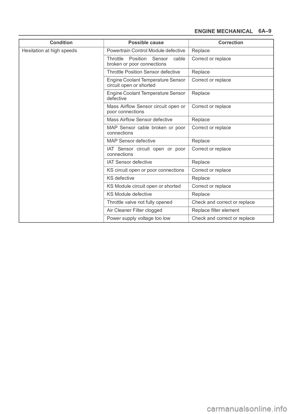
Condition CorrectionPossible cause
Hesitation at high speedsPowertrain Control Module defectiveReplace
Throttle Position Sensor cable
broken or poor connectionsCorrect or replace
Throttle Position Sensor defectiveReplace
Engine Coolant Temperature Sensor
circuit open or shortedCorrect or replace
Engine Coolant Temperature Sensor
defectiveReplace
Mass Airflow Sensor circuit open or
poor connectionsCorrect or replace
Mass Airflow Sensor defectiveReplace
MAP Sensor cable broken or poor
connectionsCorrect or replace
MAP Sensor defectiveReplace
IAT Sensor circuit open or poor
connectionsCorrect or replace
IAT Sensor defectiveReplace
KS circuit open or poor connectionsCorrect or replace
KS defectiveReplace
KS Module circuit open or shortedCorrect or replace
KS Module defectiveReplace
Throttle valve not fully openedCheck and correct or replace
Air Cleaner Filter cloggedReplace filter element
Power supply voltage too lowCheck and correct or replace
Page 966 of 6000
6A–10
ENGINE MECHANICAL
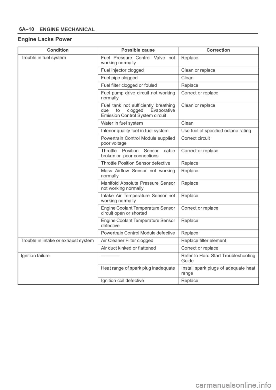
Engine Lacks Power
ConditionPossible causeCorrection
Trouble in fuel systemFuel Pressure Control Valve not
working normallyReplace
Fuel injector cloggedClean or replace
Fuel pipe cloggedClean
Fuel filter clogged or fouledReplace
Fuel pump drive circuit not working
normallyCorrect or replace
Fuel tank not sufficiently breathing
due to clogged Evaporative
Emission Control System circuitClean or replace
Water in fuel systemClean
Inferior quality fuel in fuel systemUse fuel of specified octane rating
Powertrain Control Module supplied
poor voltageCorrect circuit
Throttle Position Sensor cable
broken or poor connectionsCorrect or replace
Throttle Position Sensor defectiveReplace
Mass Airflow Sensor not working
normallyReplace
Manifold Absolute Pressure Sensor
not working normallyReplace
Intake Air Temperature Sensor not
working normallyReplace
Engine Coolant Temperature Sensor
circuit open or shortedCorrect or replace
Engine Coolant Temperature Sensor
defectiveReplace
Powertrain Control Module defectiveReplace
Trouble in intake or exhaust systemAir Cleaner Filter cloggedReplace filter element
Air duct kinked or flattenedCorrect or replace
Ignition failure————Refer to Hard Start Troubleshooting
Guide
Heat range of spark plug inadequateInstall spark plugs of adequate heat
range
Ignition coil defectiveReplace
Page 967 of 6000
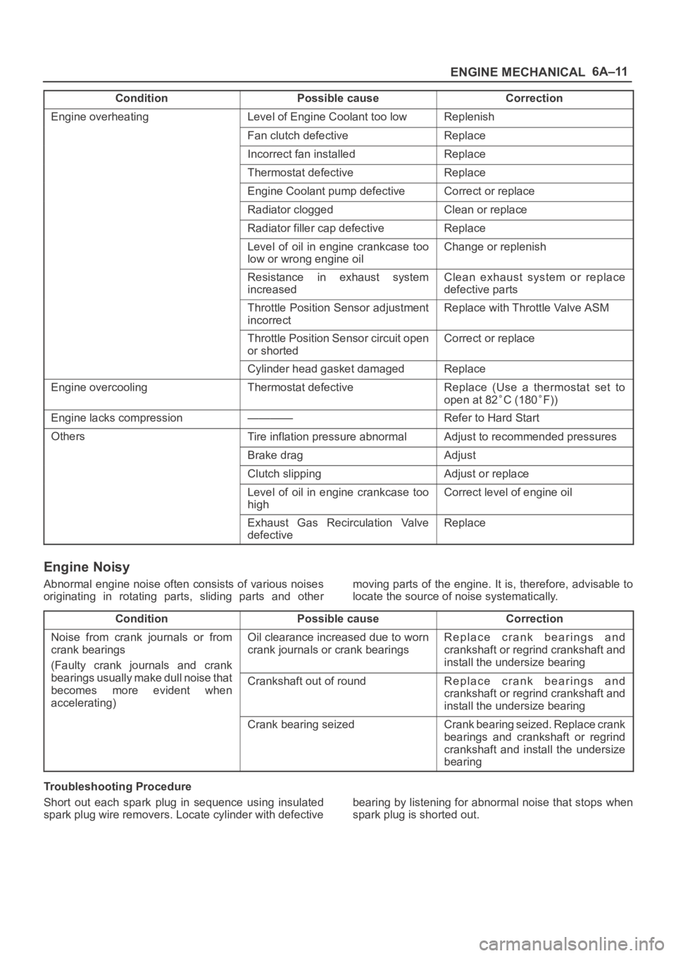
6A–11
ENGINE MECHANICAL
Condition CorrectionPossible cause
Engine overheatingLevel of Engine Coolant too lowReplenish
Fan clutch defectiveReplace
Incorrect fan installedReplace
Thermostat defectiveReplace
Engine Coolant pump defectiveCorrect or replace
Radiator cloggedClean or replace
Radiator filler cap defectiveReplace
Level of oil in engine crankcase too
low or wrong engine oilChange or replenish
Resistance in exhaust system
increasedClean exhaust system or replace
defective parts
Throttle Position Sensor adjustment
incorrectReplace with Throttle Valve ASM
Throttle Position Sensor circuit open
or shortedCorrect or replace
Cylinder head gasket damagedReplace
Engine overcoolingThermostat defectiveReplace (Use a thermostat set to
open at 82
C (180F))
Engine lacks compression————Refer to Hard Start
OthersTire inflation pressure abnormalAdjust to recommended pressures
Brake dragAdjust
Clutch slippingAdjust or replace
Level of oil in engine crankcase too
highCorrect level of engine oil
Exhaust Gas Recirculation Valve
defectiveReplace
Engine Noisy
Abnormal engine noise often consists of various noises
originating in rotating parts, sliding parts and othermoving parts of the engine. It is, therefore, advisable to
locate the source of noise systematically.
Condition
Possible causeCorrection
Noise from crank journals or from
crank bearings
(Faulty crank journals and crankOil clearance increased due to worn
crank journals or crank bearingsReplace crank bearings and
crankshaft or regrind crankshaft and
install the undersize bearing
yj
bearings usually make dull noise that
becomes more evident when
accelerating)Crankshaft out of roundReplace crank bearings and
crankshaft or regrind crankshaft and
install the undersize bearing
Crank bearing seizedCrank bearing seized. Replace crank
bearings and crankshaft or regrind
crankshaft and install the undersize
bearing
Troubleshooting Procedure
Short out each spark plug in sequence using insulated
spark plug wire removers. Locate cylinder with defectivebearing by listening for abnormal noise that stops when
spark plug is shorted out.