sensor OPEL FRONTERA 1998 Workshop Manual
[x] Cancel search | Manufacturer: OPEL, Model Year: 1998, Model line: FRONTERA, Model: OPEL FRONTERA 1998Pages: 6000, PDF Size: 97 MB
Page 969 of 6000
6A–13
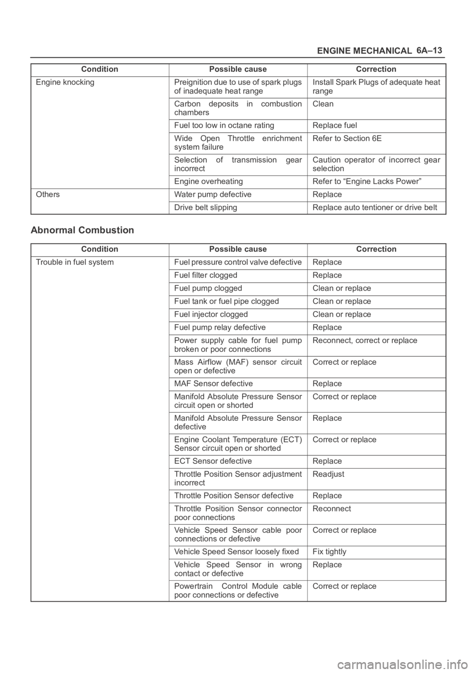
ENGINE MECHANICAL
Condition CorrectionPossible cause
Engine knockingPreignition due to use of spark plugs
of inadequate heat rangeInstall Spark Plugs of adequate heat
range
Carbon deposits in combustion
chambersClean
Fuel too low in octane ratingReplace fuel
Wide Open Throttle enrichment
system failureRefer to Section 6E
Selection of transmission gear
incorrectCaution operator of incorrect gear
selection
Engine overheatingRefer to “Engine Lacks Power”
OthersWater pump defectiveReplace
Drive belt slippingReplace auto tentioner or drive belt
Abnormal Combustion
ConditionPossible causeCorrection
Trouble in fuel systemFuel pressure control valve defectiveReplace
Fuel filter cloggedReplace
Fuel pump cloggedClean or replace
Fuel tank or fuel pipe cloggedClean or replace
Fuel injector cloggedClean or replace
Fuel pump relay defectiveReplace
Power supply cable for fuel pump
broken or poor connectionsReconnect, correct or replace
Mass Airflow (MAF) sensor circuit
open or defectiveCorrect or replace
MAF Sensor defectiveReplace
Manifold Absolute Pressure Sensor
circuit open or shortedCorrect or replace
Manifold Absolute Pressure Sensor
defectiveReplace
Engine Coolant Temperature (ECT)
Sensor circuit open or shortedCorrect or replace
ECT Sensor defectiveReplace
Throttle Position Sensor adjustment
incorrectReadjust
Throttle Position Sensor defectiveReplace
Throttle Position Sensor connector
poor connectionsReconnect
Vehicle Speed Sensor cable poor
connections or defectiveCorrect or replace
Vehicle Speed Sensor loosely fixedFix tightly
Vehicle Speed Sensor in wrong
contact or defectiveReplace
Powertrain Control Module cable
poor connections or defectiveCorrect or replace
Page 970 of 6000
6A–14
ENGINE MECHANICAL
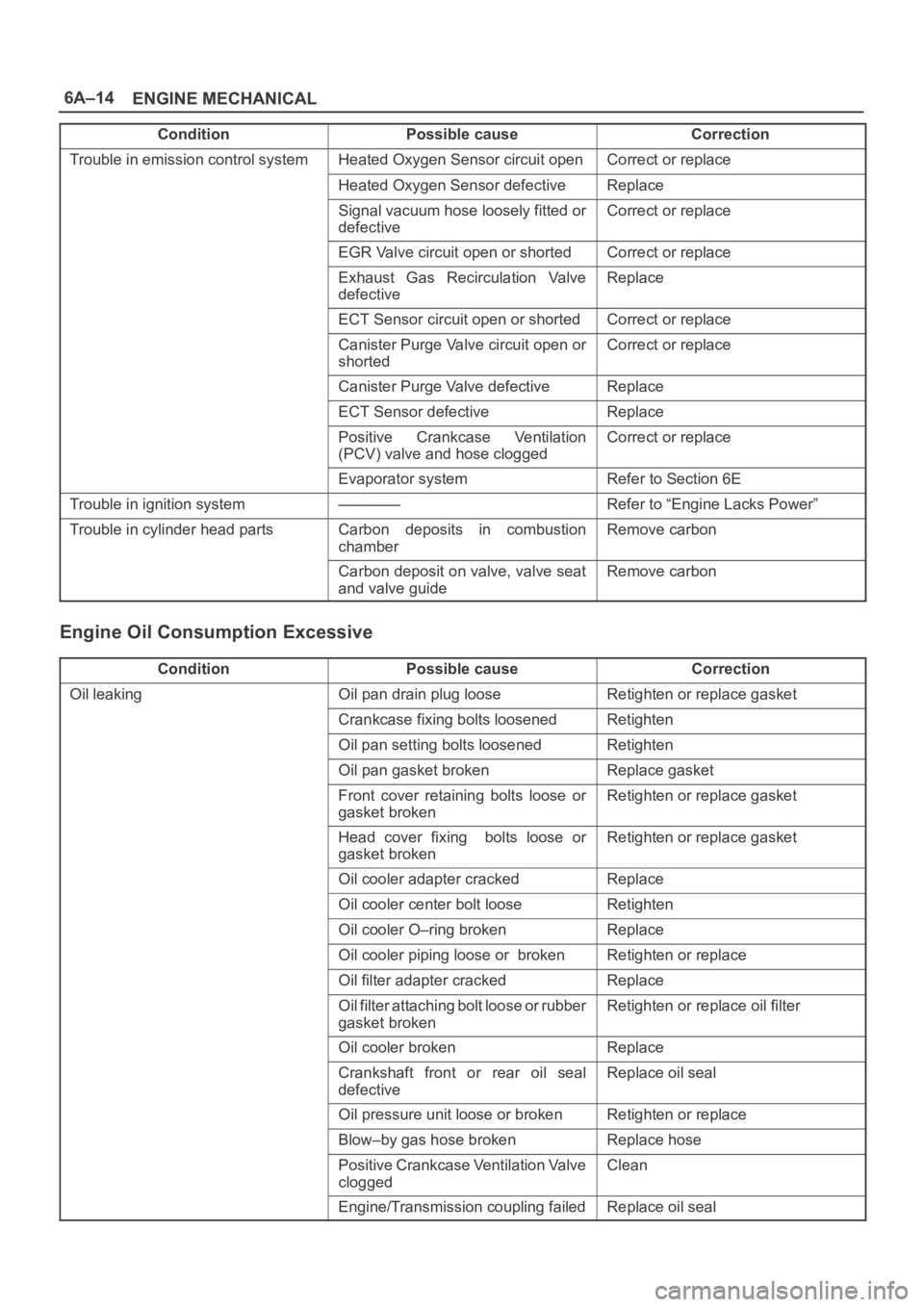
Condition CorrectionPossible cause
Trouble in emission control systemHeated Oxygen Sensor circuit openCorrect or replace
Heated Oxygen Sensor defectiveReplace
Signal vacuum hose loosely fitted or
defectiveCorrect or replace
EGR Valve circuit open or shortedCorrect or replace
Exhaust Gas Recirculation Valve
defectiveReplace
ECT Sensor circuit open or shortedCorrect or replace
Canister Purge Valve circuit open or
shortedCorrect or replace
Canister Purge Valve defectiveReplace
ECT Sensor defectiveReplace
Positive Crankcase Ventilation
(PCV) valve and hose cloggedCorrect or replace
Evaporator systemRefer to Section 6E
Trouble in ignition system————Refer to “Engine Lacks Power”
Trouble in cylinder head partsCarbon deposits in combustion
chamberRemove carbon
Carbon deposit on valve, valve seat
and valve guideRemove carbon
Engine Oil Consumption Excessive
ConditionPossible causeCorrection
Oil leakingOil pan drain plug looseRetighten or replace gasket
Crankcase fixing bolts loosenedRetighten
Oil pan setting bolts loosenedRetighten
Oil pan gasket brokenReplace gasket
Front cover retaining bolts loose or
gasket brokenRetighten or replace gasket
Head cover fixing bolts loose or
gasket brokenRetighten or replace gasket
Oil cooler adapter crackedReplace
Oil cooler center bolt looseRetighten
Oil cooler O–ring brokenReplace
Oil cooler piping loose or brokenRetighten or replace
Oil filter adapter crackedReplace
Oil filter attaching bolt loose or rubber
gasket brokenRetighten or replace oil filter
Oil cooler brokenReplace
Crankshaft front or rear oil seal
defectiveReplace oil seal
Oil pressure unit loose or brokenRetighten or replace
Blow–by gas hose brokenReplace hose
Positive Crankcase Ventilation Valve
cloggedClean
Engine/Transmission coupling failedReplace oil seal
Page 973 of 6000
6A–17
ENGINE MECHANICAL
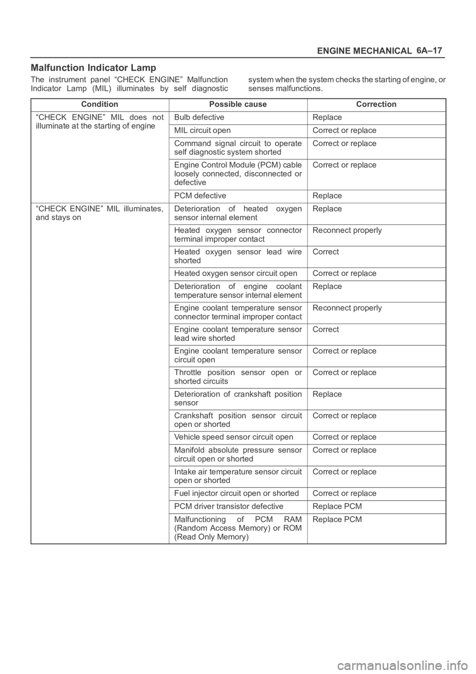
Malfunction Indicator Lamp
The instrument panel “CHECK ENGINE” Malfunction
Indicator Lamp (MIL) illuminates by self diagnosticsystem when the system checks the starting of engine, or
senses malfunctions.
Condition
Possible causeCorrection
“CHECK ENGINE” MIL does not
illuminate at the starting of engine
Bulb defectiveReplace
illuminate at the starting of engineMIL circuit openCorrect or replace
Command signal circuit to operate
self diagnostic system shortedCorrect or replace
Engine Control Module (PCM) cable
loosely connected, disconnected or
defectiveCorrect or replace
PCM defectiveReplace
“CHECK ENGINE” MIL illuminates,
and stays onDeterioration of heated oxygen
sensor internal elementReplace
Heated oxygen sensor connector
terminal improper contactReconnect properly
Heated oxygen sensor lead wire
shortedCorrect
Heated oxygen sensor circuit openCorrect or replace
Deterioration of engine coolant
temperature sensor internal elementReplace
Engine coolant temperature sensor
connector terminal improper contactReconnect properly
Engine coolant temperature sensor
lead wire shortedCorrect
Engine coolant temperature sensor
circuit openCorrect or replace
Throttle position sensor open or
shorted circuitsCorrect or replace
Deterioration of crankshaft position
sensorReplace
Crankshaft position sensor circuit
open or shortedCorrect or replace
Vehicle speed sensor circuit openCorrect or replace
Manifold absolute pressure sensor
circuit open or shortedCorrect or replace
Intake air temperature sensor circuit
open or shortedCorrect or replace
Fuel injector circuit open or shortedCorrect or replace
PCM driver transistor defectiveReplace PCM
Malfunctioning of PCM RAM
(Random Access Memory) or ROM
(Read Only Memory)Replace PCM
Page 974 of 6000
6A–18
ENGINE MECHANICAL
Cylinder Head Cover LH
Removal
1. Disconnect battery ground cable.
2. Drain engine coolant from faucet bottom of radiator.
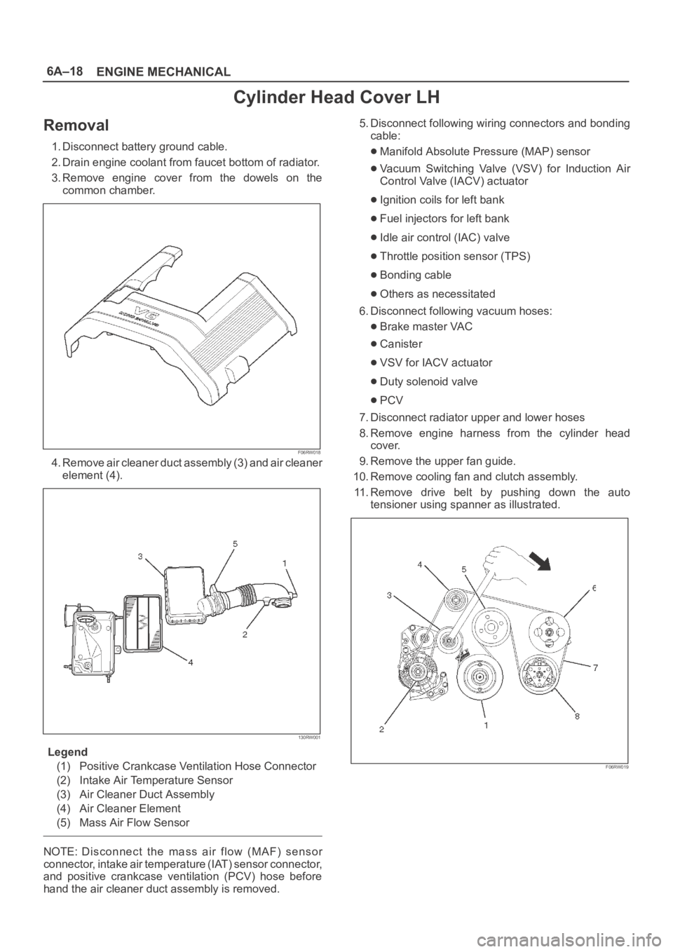
3. Remove engine cover from the dowels on the
common chamber.
F06RW018
4. Remove air cleaner duct assembly (3) and air cleaner
element (4).
130RW001
Legend
(1) Positive Crankcase Ventilation Hose Connector
(2) Intake Air Temperature Sensor
(3) Air Cleaner Duct Assembly
(4) Air Cleaner Element
(5) Mass Air Flow Sensor
NOTE: Disconnect the mass air flow (MAF) sensor
connector, intake air temperature (IAT) sensor connector,
and positive crankcase ventilation (PCV) hose before
hand the air cleaner duct assembly is removed.5. Disconnect following wiring connectors and bonding
cable:
Manifold Absolute Pressure (MAP) sensor
Vacuum Switching Valve (VSV) for Induction Air
Control Valve (IACV) actuator
Ignition coils for left bank
Fuel injectors for left bank
Idle air control (IAC) valve
Throttle position sensor (TPS)
Bonding cable
Others as necessitated
6. Disconnect following vacuum hoses:
Brake master VAC
Canister
VSV for IACV actuator
Duty solenoid valve
PCV
7. Disconnect radiator upper and lower hoses
8. Remove engine harness from the cylinder head
cover.
9. Remove the upper fan guide.
10. Remove cooling fan and clutch assembly.
11. Remove drive belt by pushing down the auto
tensioner using spanner as illustrated.
F06RW019
Page 976 of 6000
6A–20
ENGINE MECHANICAL
5. Install auto tensioner assembly and tighten the fixing
bolts to the specified torque.
Torque :
Shorter Bolt : 20 Nꞏm (2.0 Kgꞏm/14 lb ft)
Longer Bolt : 39 Nꞏm (4.0 Kgꞏm/29 lb ft)
6. Install idle pulley and bracket assembly and tighten
the fixing bolt to the specified torque.
Torque : 52 Nꞏm (5.3 Kgꞏm/38 lb ft)
7. Install fan pulley and bracket assembly and tighten
the fixing bolts and nut to the specified torque.
Torque : 22 Nꞏm (2.2 Kgꞏm/16 lb ft)
8. Install power steering oil pump pulley and tighten the
fixing bolt to the specified torque.
Torque : 78 Nꞏm (8.0 Kgꞏm/58 lb ft)
9. Install drive belt by pushing down the auto tensioner
using spanner as shown in the removal step of drive
belt.
10. Install cooling fan and clutch assembly and tighten
the fixing bolts to the specified torque.
Torque : 10 Nꞏm (1.0 Kgꞏm/87 lb in)
11. Install upper fan guide and clip both side and tighten
the fixing bolts to the specified torque.
Torque : 4 Nꞏm (0.4 Kgꞏm/35 lb in)
12. Install engine harness and tighten the fixing bolts of
the retaining clip and bracket to the specified torque.
Torque : 4 Nꞏm (0.4 Kgꞏm/35 lb in)
13. Connect radiator upper and lower hoses and clip
them securely.
14. Connect vacuum hoses of those which were
disconnected in the removal step.
15. Connect wiring connectors and bonding cable of
those which were disconnected in the removal step.
16. Install air cleaner element and air cleaner duct
assembly, and clip the both end securely.
17. Connect MAF sensor connector, IAT sensor
connector and PCV hose.
18. Install engine cover mating with the dowels.
Page 977 of 6000
6A–21
ENGINE MECHANICAL
Cylinder Head Cover RH
Removal
1. Disconnect battery ground cable.
2. Remove battery from the vehicle.
3. Drain engine coolant from faucet bottom of radiator.
4. Remove engine cover from the dowels on the
common chamber.
F06RW018
5. Remove air cleaner duct assembly (3) and air cleaner
element (4).
130RW001
Legend
(1) Positive Crankcase Ventilation Hose Connector
(2) Intake Air Temperature Sensor
(3) Air Cleaner Duct Assembly
(4) Air Cleaner Element
(5) Mass Air Flow Sensor
NOTE: Disconnect the mass air flow (MAF) sensor
connector, intake air temperature (IAT) sensor connector,
and positive crankcase ventilation (PCV) hose before
hand the air cleaner duct assembly is removed.
6. Disconnect following wiring connectors and bonding
cable:
Exhaust Gas Recirculation (EGR) valve
Fuel injectors for right bank
Ignition coils for right bank
Bonding cable
Othres as necessitated
7. Disconnect radiator upper and lower hoses.
8. Remove engine harness from the cylinder head
cover.
9. Remove the upper fan guide.
10. Remove cooling fan and clutch assembly.
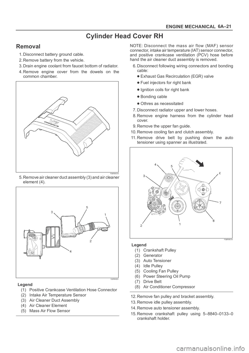
11. Remove drive belt by pushing down the auto
tensioner using spanner as illustrated.
F06RW019
Legend
(1) Crankshaft Pulley
(2) Generator
(3) Auto Tensioner
(4) Idle Pulley
(5) Cooling Fan Pulley
(6) Power Steering Oil Pump
(7) Drive Belt
(8) Air Conditioner Compressor
12. Remove fan pulley and bracket assembly.
13. Remove idle pulley assembly.
14. Remove auto tensioner assembly.
15. Remove crankshaft pulley using 5–8840–0133–0
crankshaft holder.
Page 979 of 6000
6A–23
ENGINE MECHANICAL
6. Install idle pulley assembly and tighten the fixing bolt
to the specified torque.
Torque : 52 Nꞏm (5.3 Kgꞏm/38.4 lb ft)
7. Install fan pulley and bracket assembly and tighten
the fixing bolts and nut to the specified torque.
Torque : 22 Nꞏm (2.2 Kgꞏm/16.2 lb ft)
8. Install drive belt by pushing down the auto tensioner
using spanner as shown in the removal step of drive
belt.
9. Install cooling fan clutch assembly and tighten the
fixing bolts to the specified torque.
Torque : 10 Nꞏm (1.0 Kgꞏm/88.5 lb in)
10. Install upper fan guide and clip both side and tighten
the fixing bolts to the specified torque.
Torque : 4 Nꞏm (0.4 Kgꞏm/35.4 lb in)
11. Install engine harness and tighten the fixing bolts of
the retaining clip and brackets to the specified torque.
Torque : 4 Nꞏm (0.4 Kgꞏm/35.4 lb in)
12. Connect radiator upper and lower hoses and clip
them securely.
13. Connect wiring connectors and bonding cable of
those which were disconnected in the removal step.
14. Install air cleaner element and air cleaner duct
assembly, and the clip both end securely.
15. Connect MAF sensor connector, IAT sensor
connector and PCV hose.
16. Install engine cover mating with the dowels.
Page 980 of 6000
6A–24
ENGINE MECHANICAL
Common Chamber
Removal
1. Disconnect battery ground cable.
2. Remove air cleaner duct assembly.
130RW001
Legend
(1) Positive Crankcase Ventilation Hose Connector
(2) Intake Air Temperature Sensor
(3) Air Cleaner Duct Assembly
(4) Air Cleaner Element
(5) Air Flow Sensor
3. Disconnect accelerator pedal cable from throttle body
and cable bracket.
4. Disconnect vacuum booster hose from common
chamber.
5. Disconnect connector from manifold absolute
pressure sensor, idle air control valve, throttle
position sensor, solenoid valve, electric vacuum
sensing valve, and EGR valve.
6. Disconnect vacuum hose on canister VSV and
positive crankcase ventilation hose, fuel rail
assembly with pressure control valve bracket.
7. Remove ventilation hose from throttle valve and
intake duct and remove water hose.
8. Remove the four throttle body fixing bolts.
9. Remove exhaust gas recirculation valve assembly
fixing bolt and nut on common chamber and remove
EGR valve assembly.
10. Remove two bolts from common chamber rear side
for remove fuel hose bracket.
11. Remove common chamber four bolts and four nuts
then remove the common chamber.
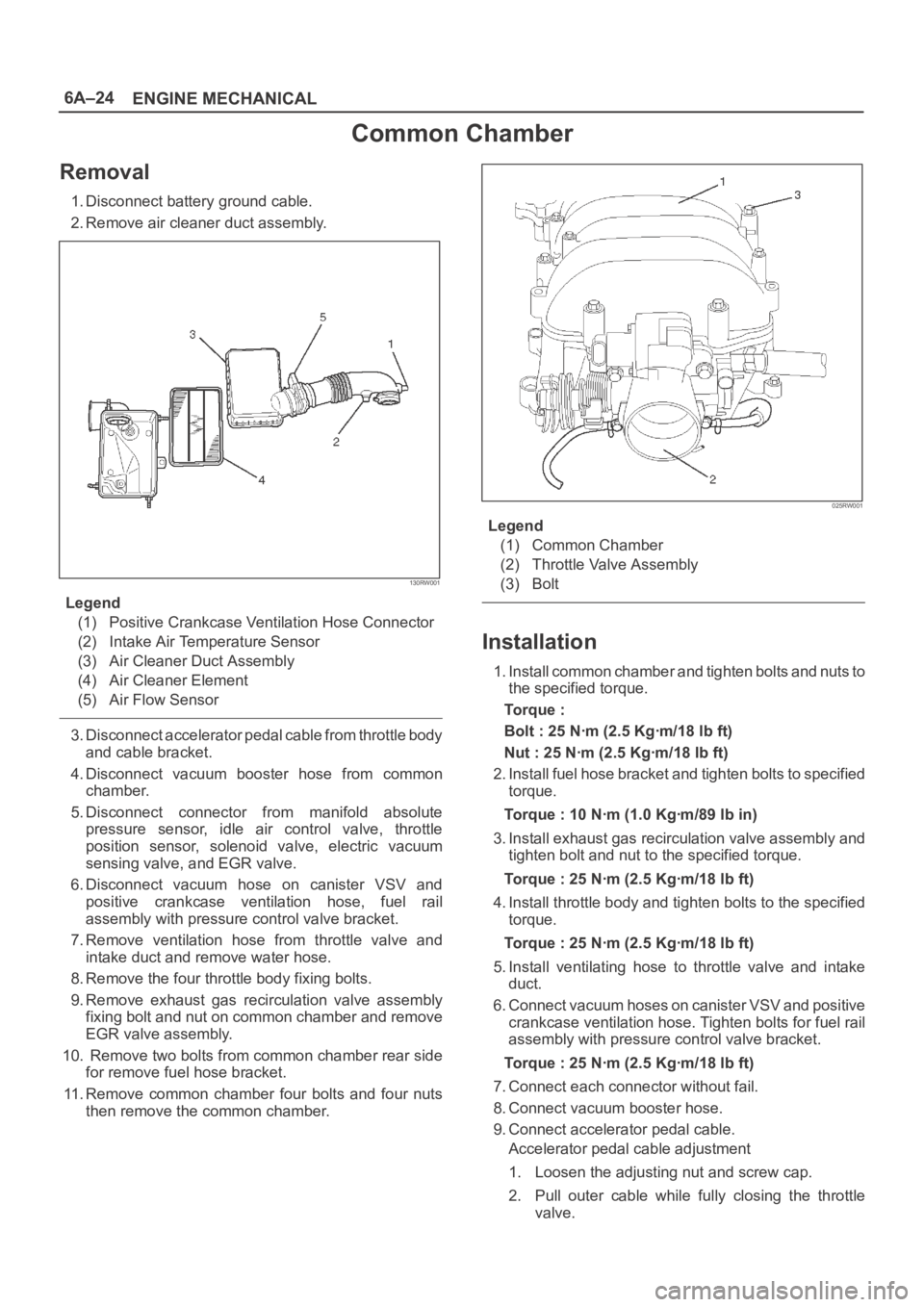
025RW001
Legend
(1) Common Chamber
(2) Throttle Valve Assembly
(3) Bolt
Installation
1. Install common chamber and tighten bolts and nuts to
the specified torque.
To r q u e :
Bolt : 25 Nꞏm (2.5 Kgꞏm/18 lb ft)
Nut : 25 Nꞏm (2.5 Kgꞏm/18 lb ft)
2. Install fuel hose bracket and tighten bolts to specified
torque.
Torque : 10 Nꞏm (1.0 Kgꞏm/89 lb in)
3. Install exhaust gas recirculation valve assembly and
tighten bolt and nut to the specified torque.
Torque : 25 Nꞏm (2.5 Kgꞏm/18 lb ft)
4. Install throttle body and tighten bolts to the specified
torque.
Torque : 25 Nꞏm (2.5 Kgꞏm/18 lb ft)
5. Install ventilating hose to throttle valve and intake
duct.
6. Connect vacuum hoses on canister VSV and positive
crankcase ventilation hose. Tighten bolts for fuel rail
assembly with pressure control valve bracket.
Torque : 25 Nꞏm (2.5 Kgꞏm/18 lb ft)
7. Connect each connector without fail.
8. Connect vacuum booster hose.
9. Connect accelerator pedal cable.
Accelerator pedal cable adjustment
1. Loosen the adjusting nut and screw cap.
2. Pull outer cable while fully closing the throttle
valve.
Page 981 of 6000

6A–25
ENGINE MECHANICAL
3. Tighten adjusting nut and lock nut temporarily.
4. Loosen adjusting nut by three turns and tighten
lock nut.
Then manually operating the throttle valve, make
sure that the valve lever returns up to the stopper
screw.
If it does not reach the stopper screw, repeat from
step 1.
035RW004
Legend
(1) Clearance
(2) Lock Nut
(3) Adjusting Nut
10. Install air cleaner duct assembly.
130RW001
Legend
(1) Positive Crankcase Ventilation Hose Connector
(2) Intake Air Temperature Sensor
(3) Air Cleaner Duct Assembly
(4) Air Cleaner Element.
(5) Mass Air Flow Sensor
Page 982 of 6000

6A–26
ENGINE MECHANICAL
Exhaust Manifold LH
Removal
1. Disconnect battery ground cable.
2. Remove air cleaner duct assembly.
130RW001
Legend
(1) Positive Crankcase Ventilation Hose Connector
(2) Intake Air Temperature Sensor
(3) Air Cleaner Duct Assembly
(4) Air Cleaner Element
(5) Mass Air Flow Sensor
3. Remove exhaust front pipe three stud nuts from
exhaust side and two nuts from rear end of exhaust
front pipe.
150RW062
Legend
(1) Exhaust Front Pipe LH
4. Remove heat protector two fixing bolts then the heat
protector.5. Remove a bolt on engine LH side for air conditioner
(A/C) compressor bracket and loosen two bolts for
A/C compressor then move A/C compressor to front
side.
6. Remove exhaust manifold eight fixing nuts and
remove exhaust manifold from the engine.
Installation
1. Install exhaust manifold and tighten exhaust manifold
fixing nuts to the specified torque with new nuts.
Torque: 57 Nꞏm (5.8 Kgꞏm/42 lb ft)
2. Install heat protector.
3. Install exhaust front pipe and tighten three stud nuts
and two nuts to the specified torque.
To r q u e :
Stud nuts: 67 Nꞏm (6.8 Kgꞏm/49 lb ft)
Nuts: 43 Nꞏm (4.4 Kgꞏm/32 lb ft)
150RW062
Legend
(1) Exhaust Front Pipe LH
4. Set A/C compressor to normal position and tighten
two bolts and a bolt to the specified torque.
Torque : 40 Nꞏm (4.1 Kgꞏm/30 lb ft)
5. Install air cleaner duct assembly.