OPEL FRONTERA 1998 Workshop Manual
FRONTERA 1998
OPEL
OPEL
https://www.carmanualsonline.info/img/37/57409/w960_57409-0.png
OPEL FRONTERA 1998 Workshop Manual
Trending: battery capacity, roof, service indicator, warning light, bolt pattern, automatic transmission fluid, key
Page 1131 of 6000
6E–14
ENGINE DRIVEABILITY AND EMISSIONS
PCM Wiring Diagram (9 of 11) Except EXP and SOUTH AFRICA
D06RW099
Page 1132 of 6000
6E–15 ENGINE DRIVEABILITY AND EMISSIONS
PCM Wiring Diagram (10 of 11) For EXPORT and SOUTH AFRICA
D06RW141
Page 1133 of 6000
6E–16
ENGINE DRIVEABILITY AND EMISSIONS
PCM Wiring Diagram (11 of 11)
D06RW136
Page 1134 of 6000

6E–17 ENGINE DRIVEABILITY AND EMISSIONS
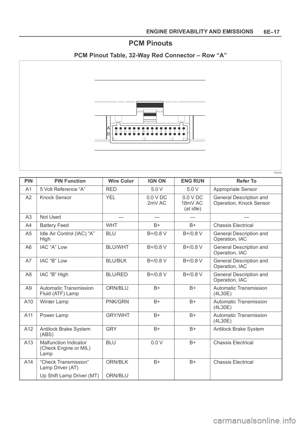
PCM Pinouts
PCM Pinout Table, 32-Way Red Connector – Row “A”
TS23344
PINPIN FunctionWire ColorIGN ONENG RUNRefer To
A15 Volt Reference “A”RED5.0 V5.0 VAppropriate Sensor
A2Knock SensorYEL0.0 V DC
2mV AC0.0 V DC
18mV AC
(at idle)General Description and
Operation, Knock Sensor
A3Not Used————
A4Battery FeedWHTB+B+Chassis Electrical
A5Idle Air Control (IAC) “A”
HighBLUB+/0.8 VB+/0.8 VGeneral Description and
Operation, IAC
A6IAC “A” LowBLU/WHTB+/0.8 VB+/0.8 VGeneral Description and
Operation, IAC
A7IAC “B” LowBLU/BLKB+/0.8 VB+/0.8 VGeneral Description and
Operation, IAC
A8IAC “B” HighBLU/REDB+/0.8 VB+/0.8 VGeneral Description and
Operation, IAC
A9Automatic Transmission
Fluid (ATF) LampORN/BLUB+B+Automatic Transmission
(4L30E)
A10Winter LampPNK/GRNB+B+Automatic Transmission
(4L30E)
A11Power LampGRY/WHTB+B+Automatic Transmission
(4L30E)
A12Antilock Brake System
(ABS)GRYB+B+Antilock Brake System
A13Malfunction Indicator
(Check Engine or MIL)
LampBLU0.0 VB+Chassis Electrical
A14“Check Transmission”
Lamp Driver (AT)ORN/BLKB+B+Chassis Electrical
Up Shift Lamp Driver (MT)ORN/BLU
Page 1135 of 6000
6E–18
ENGINE DRIVEABILITY AND EMISSIONS
PINRefer To ENG RUN IGN ON Wire Color PIN Function
A15EVAPRED/BLUB+5.0 V—
A16Band Apply (AT)
Air Pump (MT)BRN/YELB+B+Automatic Transmission
(4L30E)
Page 1136 of 6000

6E–19 ENGINE DRIVEABILITY AND EMISSIONS
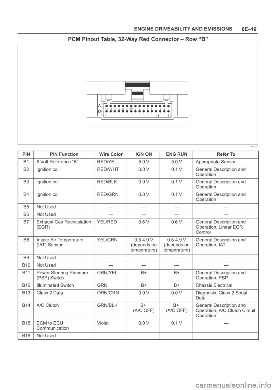
PCM Pinout Table, 32-Way Red Connector – Row “B”
TS23344
PINPIN FunctionWire ColorIGN ONENG RUNRefer To
B15 Volt Reference “B”RED/YEL5.0 V5.0 VAppropriate Sensor
B2lgnition coilRED/WHT0.0 V0.1 VGeneral Description and
Operation
B3lgnition coilRED/BLK0.0 V0.1 VGeneral Description and
Operation
B4lgnition coilRED/GRN0.0 V0.1 VGeneral Description and
Operation
B5Not Used————
B6Not Used————
B7Exhaust Gas Recirculation
(EGR)YEL/RED0.6 V0.6 VGeneral Description and
Operation, Linear EGR
Control
B8Intake Air Temperature
(IAT) SensorYEL/GRN0.5-4.9 V
(depends on
temperature)0.5-4.9 V
(depends on
temperature)General Description and
Operation, IAT
B9Not Used————
B10Not Used————
B11Power Steering Pressure
(PSP) SwitchGRN/YELB+B+General Description and
Operation, PSP
B12Illuminated SwitchGRNB+B+Chassis Electrical
B13Class 2 DataORN/GRN0.0 V0.0 VDiagnosis, Class 2 Serial
Data
B14A/C ClutchGRN/BLKB+
(A/C OFF)B+
(A/C OFF)General Description and
Operation, A/C Clutch Circuit
Operation
B15ECM to ECU
CommunicationViolet0.0 V0.1 V—
B16Not Used————
Page 1137 of 6000

6E–20
ENGINE DRIVEABILITY AND EMISSIONS
PCM Pinout Table, 32-Way White Connector – Row “C” (For EC)
TS23345
PINPIN FunctionWire ColorIGN ONENG RUNRefer To
C1Injector Cylinder #4GRN/REDB+B+General Description and
Operation, Fuel Injector
C2Shift “B” SolenoidBRN/BLK0.0 V0.0 VAutomatic Transmission
(4L30E)
C3Injector Cylinder #6GRN/YELB+B+General Description and
Operation, Fuel Injector
C4Ignition Control (IC)
Cylinder #1RED0.0 V0.1 VGeneral Description and
Operation, Fuel Injector
C5Crankshaft Position
Sensor, “A” CircuitYEL0.3 V to 5 V2.2 VGeneral Description and
Operation, Crankshaft
Position Sensor
C6Not Used————
C7PCM GroundYEL0.0 V0.0 VChassis Electrical
C8PCM GroundBLK/PNK0.0 V0.0 VChassis Electrical
C9PCM GroundBLK/BLU0.0 V0.0 VChassis Electrical
C10TachometerBLK/RED8.8 V10.0 V
(at idle)Chassis Electrical
C11Variable Intake ManifoldYEL/BLK0.0 VB+ (rpm
3600 over)Manual Transmission
C12Alternator Control GainWHT/BLU10.5 VB+Chassis Electrical
C13Fuel PWMBLU/PNKB+B+—
C14Bank 2 HO2S 1 HighPNK0.4 V0.1-0.9 VGeneral Description and
Operation, Fuel HO2S 1
C15Bank 2 HO2S 1 LowBLU0.0 V0.1 VGeneral Description and
Operation, Fuel HO2S 1
C16Not Used————
Page 1138 of 6000

6E–21 ENGINE DRIVEABILITY AND EMISSIONS
PCM Pinout Table, 32-Way White Connector – Row “C” (For except EC)
TS23345
PINPIN FunctionWire ColorIGN ONENG RUNRefer To
C1Injector Cylinder #4GRN/REDB+B+General Description and
Operation, Fuel Injector
C2Shift “B” SolenoidBRN/BLK0.0 V0.0 VAutomatic Transmission
(4L30E)
C3Injector Cylinder #6GRN/YELB+B+General Description and
Operation, Fuel Injector
C4Ignition Control (IC)
Cylinder #1RED0.0 V0.1 VGeneral Description and
Operation, Fuel Injector
C5Crankshaft Position
Sensor, “A” CircuitYEL0.3 V to 5 V2.2 VGeneral Description and
Operation, Crankshaft
Position Sensor
C6Not Used————
C7PCM GroundBLK/BLU0.0 V0.0 VChassis Electrical
C8PCM GroundBLK/PNK0.0 V0.0 VChassis Electrical
C9PCM GroundBLK/BLU0.0 V0.0 VChassis Electrical
C10TachometerBLK/RED8.8 V10.0 V
(at idle)Chassis Electrical
C11Variable Intake ManifoldYEL/BLK0.0 VB+ (rpm
3600 over)Manual Transmission
C12Not Used————
C13Not Used————
C14Not Used————
C15Not Used————
C16Not Used————
Page 1139 of 6000

6E–22
ENGINE DRIVEABILITY AND EMISSIONS
PCM Pinout Table, 32-Way White Connector – Row “D”
(For except EXPORT and SOUTH AFRICA)
TS23345
PINPIN FunctionWire ColorIGN ONENG RUNRefer To
D1Injector Cylinder #2GRN/ORNB+B+General Description and
Operation, Fuel Injector
D2Torque Converter Clutch
(TCC)BRN/BLU0.0 V0.0 VOn-Vehicle Service, Torque
Converter Clutch
D3Injector Cylinder #1GRN/WHTB+B+General Description and
Operation, Fuel Injector
D4Serial Data (8192)ORN5.0 V5.0 VChassis Electrical
D5Ignition Control, Cylinder
#5RED/YEL0.0 V0.1 VGeneral Description and
Operation, Ignition Coil
D6Ignition Control, Cylinder
#3RED/BLUE0.0 V0.0 VGeneral Description and
Operation, Ignition Coil
D7VSS Input / IMOB
ResponseWHT/BLK0.0 V0.1 V
(at rest)Chassis Electrical
D8Sensor Ground 5V
Reference A ReturnGRN0.0 V0.0 VAppropriate Sensor
D9Sensor Ground 5 V
Reference B ReturnGRY0.0 V0.0 VAppropriate Sensor
D10Mass Air Flow (MAF)YEL4.9 V4.2 VGeneral Description, Mass
Air Flow Sensor
D11Camshaft Position SensorWHT5.0 V or less
than 1.0 V4.6 VGeneral Description and
Operation, Camshaft
Position Sensor
D12Not Used————
D13Not Used————
D14Bank 1 HO2S 1 LowGRN0.0 V0.1 VGeneral Description and
Operation, Fuel HO2S 1
D15Bank 1 HO2S 1 SignalRED0.4 V0.1-0.9 VGeneral Description and
Operation, Fuel HO2S 1
D16Not Used————
Page 1140 of 6000

6E–23 ENGINE DRIVEABILITY AND EMISSIONS
PCM Pinout Table, 32-Way White Connector – Row “D”
(For EXPORT and SOUTH AFRICA)
TS23345
PINPIN FunctionWire ColorIGN ONENG RUNRefer To
D1Injector Cylinder #2GRN/ORNB+B+General Description and
Operation, Fuel Injector
D2Torque Converter Clutch
(TCC)BRN/BLU0.0 V0.0 VOn-Vehicle Service, Torque
Converter Clutch
D3Injector Cylinder #1GRN/WHTB+B+General Description and
Operation, Fuel Injector
D4Serial Data (8192)ORN5.0 V5.0 VChassis Electrical
D5Ignition Control, Cylinder
#5RED/YEL0.0 V0.1 VGeneral Description and
Operation, Ignition Coil
D6Ignition Control, Cylinder
#3RED/BLUE0.0 V0.0 VGeneral Description and
Operation, Ignition Coil
D7VSS Input / IMOB
ResponseLIGHT
GRN/WHT0.0 V0.1 V
(at rest)Chassis Electrical
D8Sensor Ground 5V
Reference A ReturnGRN0.0 V0.0 VAppropriate Sensor
D9Sensor Ground 5 V
Reference B ReturnGRY0.0 V0.0 VAppropriate Sensor
D10Mass Air Flow (MAF)YEL4.9 V4.2 VGeneral Description, Mass
Air Flow Sensor
D11Camshaft Position SensorWHT5.0 V or less
than 1.0 V4.6 VGeneral Description and
Operation, Camshaft
Position Sensor
D12Not Used————
D13Not Used————
D14Not Used————
D15Not Used————
D16Not Used————
Trending: wiring diagram, oil pressure, Drawing, weight, height, fold seats, fuel consumption


