check oil OPEL FRONTERA 1998 Workshop Manual
[x] Cancel search | Manufacturer: OPEL, Model Year: 1998, Model line: FRONTERA, Model: OPEL FRONTERA 1998Pages: 6000, PDF Size: 97 MB
Page 1832 of 6000
ENGINE MECHANICAL 6A – 99
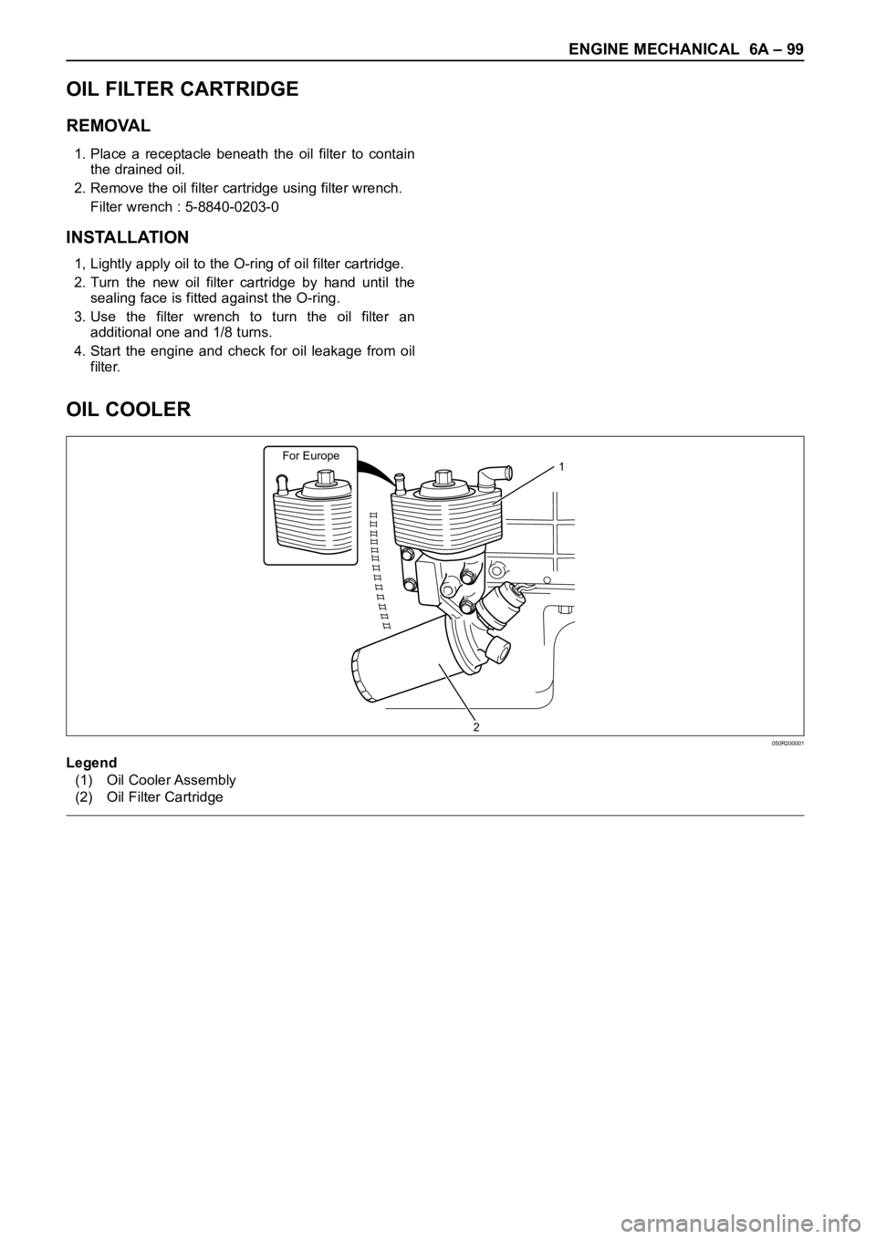
OIL COOLER
For Europe1
2050R200001
Legend
(1) Oil Cooler Assembly
(2) Oil Filter Cartridge
OIL FILTER CARTRIDGE
REMOVAL
1. Place a receptacle beneath the oil filter to contain
the drained oil.
2. Remove the oil filter cartridge using filter wrench.
Filter wrench : 5-8840-0203-0
INSTALLATION
1, Lightly apply oil to the O-ring of oil filter cartridge.
2. Turn the new oil filter cartridge by hand until the
sealing face is fitted against the O-ring.
3. Use the filter wrench to turn the oil filter an
additional one and 1/8 turns.
4. Start the engine and check for oil leakage from oil
filter.
Page 1833 of 6000

6A – 100 ENGINE MECHANICAL
REMOVAL
1. Disconnect battery ground cable
2. Drain engine coolant
3. Remove front exhaust pipe
4. Remove heat protector
5. Remove exhaust valve assembly
6. Oil cooler assembly
1) Remove water hoses from inlet and outlet pipe.
2) Put rag beneath side of oil cooler to prevent oil
leaking.
3) Remove fixing bolts and oil cooler assembly.
INSTALLATION
1. Oil Cooler
1) Tighten oil cooler fixing bolt to the specified
torque and connect water hose.
Torque: 29 Nꞏm (3.0 kgꞏm/22 lb ft)
2. Exh. Valve Assembly
1) Install exhaust valve assembly with gasket and
tighten fixing bolts to the specified torque.
Torque: 27 Nꞏm (2.7 kgꞏm/20 lb ft)
3. Heat Protector
4. Front Exhaust Pipe
1) Install front exhaust pipe and tighten fixing bolts
to the specified torque.
Exh. Valve Side: 67 Nꞏm (6.8 kgꞏm/50 lb ft)
Intermediate Pipe Side: 43 Nꞏm (4.4 kgꞏm/32 lb ft)
5. Fill engine coolant.
6. Connect battery ground cable.
7. Start engine and check for oil and water leakage
carefully.
Page 1838 of 6000

ENGINE COOLING 6B – 5
ENGINE COOLANT CHANGE
PROCEDURE
1. To change engine coolant, make sure that the
engine is cool.
WARNING:
When the coolant is heated to a high temperature,
be sure not to loosen or remove the radiator cap.
Otherwise you might get scalded by hot vapor or
boiling water. To open the radiator cap, put a piece
of thick cloth on the cap and loosen the cap slowly
to reduce the pressure once the coolant has
become cooler.
2. Open radiator cap and drain the cooling system by
loosening the drain valve on the radiator and on the
cylinder body.
NOTE: For best results it is suggested that the engine
cooling system be flushed at least once a year. It is
advisable to flush the interior of the cooling system
including the radiator before using anti-freeze
(ethylene-glycol based).
Replace damaged rubber hoses as the engine anti-
freeze coolant is liable to leak out even minor cracks.
Isuzu recommends using Isuzu genuine anti-freeze
(ethylene-glycol based) or equivalent, for the cooling
system and not add any inhibitors or additives.
CAUTION:
A failure to correctly fill the engine cooling system
in changing or topping off coolant may sometimes
cause the coolant to overflow from the filler neck
even before the engine and radiator are completely
full.
If the engine runs under this condition, shortage of
coolant may possibly result in engine overheating.
To avoid such trouble, the following precautions
should be taken in filling the system.
3. To refill engine coolant, pour coolant up to filler neck
using a filling hose which is smaller in outside
diameter than the filler neck. Otherwise air between
the filler neck and the filling hose will block entry,
preventing the system from completely filling up.
4. Keep a filling rate of 9 liter/min. or less. Filling over
this maximum rate may force air inside the engine
and radiator.
And also, the coolant overflow will increase, making
it difficult to determine whether or not the system is
completely full.
5. After filling the system full, pull out the filling hose
and check to see if air trapped in the system is
dislodged and the coolant level goes down. Should
the coolant level go down, repeat topping-off until
there is no more drop in the coolant level.
6. Directly after filling the radiator, fill the reservoir to
the maximum level.
7. Install and tighten radiator cap and start the engine.
After idling for 2 to 3 minutes, stop the engine and
reopen radiator cap. If the water level is lower,
replenish.WARNING:
When the coolant is heated to a high temperature,
be sure not to loosen or remove the radiator cap.
Otherwise you might get scalded by hot vapor or
boiling water. To open the radiator cap, put a piece
of thick cloth on the cap and loosen the cap slowly
to reduce the pressure once the coolant has
become cooler.
8. After tightening radiator cap, warm up the engine at
about 2,000 rpm.
Set heater adjustment to the highest temperature
position, and let the coolant circulate also into
heater water system.
9. Check to see the thermostat has opened by the
needle position of a water thermometer, conduct a
5-minute idle again and stop the engine.
10. When the engine has been cooled, check filler neck
for water level and replenish if required. Should
extreme shortage of coolant be found, check the
coolant system and reservoir tank hose for leakage.
11. Fill the coolant into the reservoir tank up to “MAX”
line.
Page 1846 of 6000

ENGINE FUEL 6C – 1
ENGINE FUEL
CONTENTS
GENERAL DESCRIPTION
General Description . . . . . . . . . . . . . . . . . . 6C–1
On-Vehicle Service . . . . . . . . . . . . . . . . . . 6C–7
Fuel Filter Assembly . . . . . . . . . . . . . . . . 6C–7
Fuel Filter Cartridge . . . . . . . . . . . . . . . . 6C–7
Injector . . . . . . . . . . . . . . . . . . . . . . . . . . 6C–9
Fuel Pump Pipe . . . . . . . . . . . . . . . . . . . 6C–13High Pressure Oil Pump . . . . . . . . . . . . . 6C–15
Fuel Tank . . . . . . . . . . . . . . . . . . . . . . . . 6C–20
Fuel Gauge Unit . . . . . . . . . . . . . . . . . . . 6C–21
Fuel Filler Cap . . . . . . . . . . . . . . . . . . . . 6C–21
To realize the compatibility between low exhaust
emission and high engine output, an HEUI
(Hydraulically actuated Electronically controlled Unit
Injector) system, has been introduced. This system is
comprised of a hydraulic system, fuel system, and
electronic control system, using a high-pressure oil
pump in place of the conventional fuel injection pump.
The oil pressurized by means of this pump and by
signals from the ECM (Electronic Control Module)
actuates the fuel injector provided for each cylinder.
Inside of the fuel injector, fuel pressure is increased due
to the high-pressure oil. The ECM detects the driving
state of the vehicle, forms, signals sent by engine and
other part sensors, which determines the optimum fuel
injection amount and timing, thus controlling the fuel
injectors. Thus high engine output, good fuel economy,
and low exhaust emission are realized.When working on the fuel system, there are several
things to keep in mind:
1) Any time the fuel system is being worked on,
disconnect the negative battery cable except for
those tests where battery voltage is required.
2) Always keep a dry chemical (Class B) fire
extinguisher near the work area.
3) Replace all pipes with the same pipe and fittings
that were removed.
Clean and inspect “O” rings. Replace where
required.
4) Always relieve the line pressure before servicing
any fuel system components.
5) Do not attempt repairs on the fuel system until you
have read the instructions and checked the pictures
relating to that repair.
6) After maintenance work, push priming pump and
send enough fuel to the fuel system before starting
the engine.
NOTE: In comparison with the conventional engine,
the capacity of fuel passage in the 4JX1 engine is
larger. It takes the priming pump more time to fill the
engine with fuel.
Page 1849 of 6000
6C – 4 ENGINE FUEL
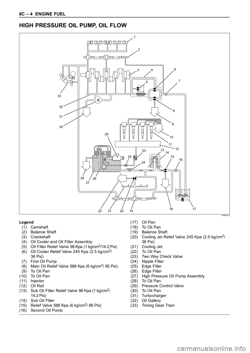
HIGH PRESSURE OIL PUMP, OIL FLOW
P
33
32
31
30
1
2
3
4
56
8
97
10
11
12
13
14 23 29
25
28
27262415
16
17 18
19 20 21 22
Legend
(1) Camshaft
(2) Balance Shaft
(3) Crankshaft
(4) Oil Cooler and Oil Filter Assembly
(5) Oil Filter Relief Valve 98 Kpa (1 kg/cm
2/14.2 Psi)
(6) Oil Cooler Relief Valve 245 Kpa (2.5 kg/cm2/
36 Psi)
(7) First Oil Pump
(8) Main Oil Relief Valve 588 Kpa (6 kg/cm
2/ 85 Psi)
(9) To Oil Pan
(10) To Oil Pan
(11) Injector
(12) Oil Rail
(13) Sub Oil Filter Relief Valve 98 Kpa (1 kg/cm
2/
14.2 Psi)
(14) Sub Oil Filter
(15) Relief Valve 588 Kpa (6 kg/cm
2/ 85 Psi)
(16) Second Oil Pump(17) Oil Pan
(18) To Oil Pan
(19) Balance Shaft
(20) Cooling Jet Relief Valve 245 Kpa (2.5 kg/cm
2/
36 Psi)
(21) Cooling Jet
(22) To Oil Pan
(23) Two Way Check Valve
(24) Nipple Filter
(25) Edge Filter
(26) Edge Filter
(27) High Pressure Oil Pump Assembly
(28) To Oil Pan
(29) Pressure Control Valve
(30) To Oil Pan
(31) Turbocharger
(32) Oil Gallery
(33) Timing Gear Train
040RW018
Page 1859 of 6000

6C – 14 ENGINE FUEL
NOTE:
1) Do not apply oil to the eye bolt.
2) Do not bend the fuel pump pipe.
5. Tifhten cap nut to specified torque.
Torque : 13 Nꞏm (1.3 kgꞏm/113 lb ft)
NOTE: Do not apply oil to the cap nut.
6. Start the engine, check that the fuel leakage is not
found.
Page 1879 of 6000
6D – 12 ENGINE ELECTRICAL
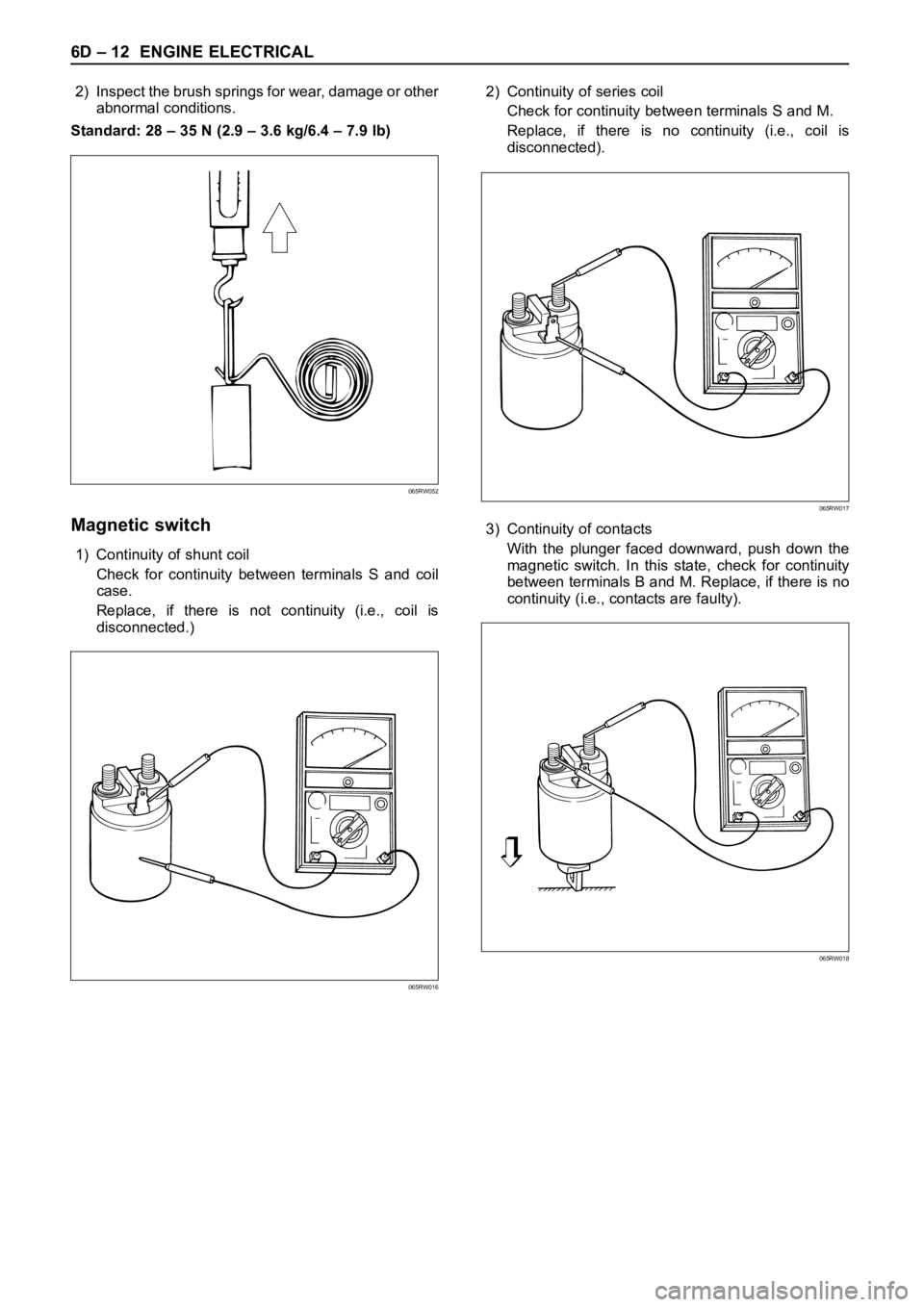
2) Inspect the brush springs for wear, damage or other
abnormal conditions.
Standard: 28 – 35 N (2.9 – 3.6 kg/6.4 – 7.9 lb)
Magnetic switch
1) Continuity of shunt coil
Check for continuity between terminals S and coil
case.
Replace, if there is not continuity (i.e., coil is
disconnected.)2) Continuity of series coil
Check for continuity between terminals S and M.
Replace, if there is no continuity (i.e., coil is
disconnected).
3) Continuity of contacts
With the plunger faced downward, push down the
magnetic switch. In this state, check for continuity
between terminals B and M. Replace, if there is no
continuity (i.e., contacts are faulty).
065RW052
065RW017
065RW018
065RW016
Page 1883 of 6000
6D – 16 ENGINE ELECTRICAL
DIAGNOSIS
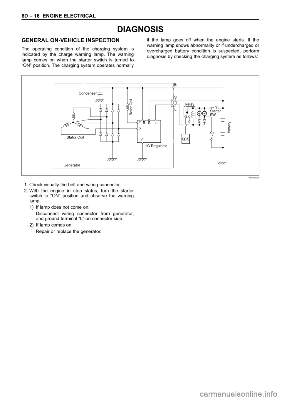
GENERAL ON-VEHICLE INSPECTION
The operating condition of the charging system is
indicated by the charge warning lamp. The warning
lamp comes on when the starter swtich is turned to
“ON” position. The charging system operates normallyif the lamp goes off when the engine starts. If the
warning lamp shows abnormality or if undercharged or
overcharged battery condition is suspected, perform
diagnosis by checking the charging system as follows:
Condenser
GeneratorStator Coil
IC RegulatorStarter
SW
Rotor Coil
Battery
P F
EBS LRelay B
S
L
QOS
065R200028
1. Check visually the belt and wiring connector.
2. With the engine in stop status, turn the starter
switch to “ON” position and observe the warning
lamp.
1) If lamp does not come on:
Disconnect wiring connector from generator,
and ground terminal “L” on connector side.
2) If lamp comes on:
Repair or replace the generator.
Page 1887 of 6000
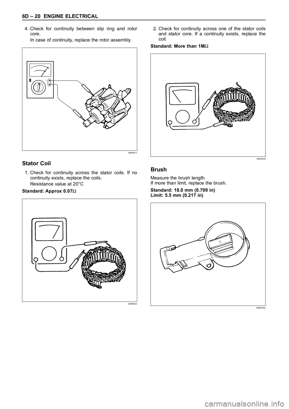
6D – 20 ENGINE ELECTRICAL
4. Check for continuity between slip ring and rotor
core.
In case of continuity, replace the rotor assembly.
Stator Coil
1. Check for continuity across the stator coils. If no
continuity exists, replace the coils.
Resistance value at 20°C
Standard: Approx 0.07
2. Check for continuity across one of the stator coils
and stator core. If a continuity exists, replace the
coil.
Standard: More than 1M
Brush
Measure the brush length.
If more than limit, replace the brush.
Standard: 18.0 mm (0.709 in)
Limit: 5.5 mm (0.217 in)
+
−
066RS017
066RS035
066RW024066RS034
Page 1888 of 6000
ENGINE ELECTRICAL 6D – 21
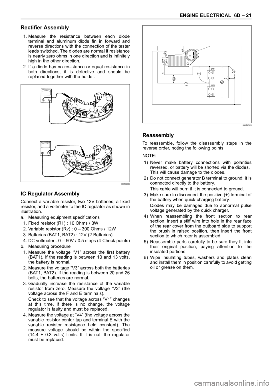
Rectifier Assembly
1. Measure the resistance between each diode
terminal and aluminum diode fin in forward and
reverse directions with the connection of the tester
leads switched. The diodes are normal if resistance
is nearly zero ohms in one direction and is infinitely
high in the other direction.
2. If a diode has no resistance or equal resistance in
both directions, it is defective and should be
replaced together with the holder.
IC Regulator Assembly
Connect a variable resistor, two 12V batteries, a fixed
resistor, and a voltmeter to the IC regulator as shown in
illustration.
a. Measuring equipment specifications
1. Fixed resistor (R1) : 10 Ohms / 3W
2. Variable resistor (Rv) : 0 – 300 Ohms / 12W
3. Batteries (BAT1, BAT2) : 12V (2 Batteries)
4. DC voltmeter : 0 – 50V / 0.5 steps (4 Check points)
b. Measuring procedure
1. Measure the voltage “V1” across the first battery
(BAT1). If the reading is between 10 and 13 volts,
the battery is normal.
2. Measure the voltage “V3” across both the batteries
(BAT1, BAT2). If the reading is between 20 and 26
bolts, the batteries are normal.
3. Gradually increase the resistance of the variable
resistor from zero. Measure the voltage “V2” (the
voltage across the F and E terminals).
Check to see that the voltage across “V1” changes
at this time. If there is no change, the voltage
regulator is faulty and must be replaced.
4. Measure the voltage at “V4” (the voltage across the
variable resistor center tap and terminal E with the
variable resistor resistance held constant). The
measure voltage should be within the specified
(14.4 ± 0.3 volts) limits. If it is not, the regulator
must be replaced.
Reassembly
To reassemble, follow the disassembly steps in the
reverse order, noting the following points:
NOTE:
1) Never make battery connections with polarities
reversed, or battery will be shorted via the diodes.
This will cause damage to the diodes.
2) Do not connect generator B terminal to ground; it is
connected directly to the battery.
This cable will burn if it is connected to ground.
3) Make sure to disconnect the positive (+) terminal of
the battery when quick-charging battery.
Diodes may be damaged due to abnormal pulse
voltage generated by the quick charger.
4) When reassembling the front section to rear
section, insert a stiff wire into hole in the rear face
of the rear cover from the outboard side to support
the brush in raised position, then insert the front
section to which rotor is assembled.
5) Reassemble parts carefully to be sure they fit into
their original position, paying attention to the
insulated portions.
6) Wipe insulating tubes, washers and plates clean
and install them in position carefully to avoid getting
oil or grease on them.
066RS036
R
EBS
R1RV
BAT2 BAT1
V2V3
V4V1+
−
+
−
066RW029