OBD port OPEL FRONTERA 1998 User Guide
[x] Cancel search | Manufacturer: OPEL, Model Year: 1998, Model line: FRONTERA, Model: OPEL FRONTERA 1998Pages: 6000, PDF Size: 97 MB
Page 1172 of 6000

6E–55 ENGINE DRIVEABILITY AND EMISSIONS
Damaged harness–Inspect the wiring harness for
damage. If the harness appears to OK, observe the
A/C clutch while moving connectors and wiring
harnesses related to the A/C. A sudden clutch
malfunction will indicate the source of the intermittent
fault.
A/C Clutch Diagnosis
This chart should be used for diagnosing the electrical
p o r t i o n o f t h e A / C c o m p r e s s o r c l u t c h c i r c u i t . A Te c h 2 w i l l
be used in diagnosing the system. The Tech 2 has the
ability to read the A/C request input to the PCM. The Tech
2 can display when the PCM has commanded the A/C
clutch “ON.” The Tech 2 should have the ability to
override the A/C request signal and energize the A/C
compressor relay.
Test Description
IMPORTANT:Do not engage the A/C compressor
clutch with the engine running if an A/C mode is not
selected at the A/C control switch.
The numbers below refer to the step numbers on the
Diagnostic Chart:3. This a test determine is the problem is with the
refrigerant system. If the switch is open, A/C
pressure gauges will be used to determine if the
pressure switch is faulty or if the system is partially
discharged or empty.
4. Although the normal complaint will be the A/C clutch
failing to engage, it is possible for a short circuit to
cause the clutch to run when A/C has not been
selected. This step is a test for that condition.
7. There is an extremely low probability that both relays
will fail at the same time, so the substitution process
is one way to check the A/C Thermostat relay. Use
a known good relay to do a substitution check.
9. The blower system furnishes a ground for the A/C
control circuit, and it also shares a power source
through the Heater and A/C Relay. The blower
must be “ON” in order to test the A/C system.
A/C Clutch Control Circuit Diagnosis
StepActionVa l u e ( s )Ye sNo
1Was the “On-Board Diagnostic (OBD) System Check”
performed?
—Go to Step 2
Go to OBD
System
Check
2Are any other DTCs stored?
—
Go to the
other DTC
chart(s) first
Go to Step 3
31. Disconnect the electrical connector at the pressure
switch located on the receiver/drier.
2. Use an ohmmeter to check continuity across the
pressure switch.
Is the pressure switch open?
—
Go to Air
Conditioning
to diagnose
the cause of
the open
pressure
switch
Go to Step 4
4IMPORTANT:Before continuing with the diagnosis, the
following conditions must be met:
The intake air temperature must be greater than
15
C. (60F).
The engine coolant temperature must be less
than 119
C (246F).
1. A/C “OFF.”
2. Start the engine and idle for 1 minute.
3. Observe the A/C compressor.
Is the A/C compressor clutch engaged even though
A/C has not been requested?
—Go to Step 45Go to Step 5
51. Idle the engine.
2. A/C “ON”.
3. Blower “ON”.
4. Observe the A/C compressor.
Is the A/C compressor magnetic clutch engaged?
—
Refer to
Diagnostic
Aids
Go to Step 6
Page 1179 of 6000
6E–62
ENGINE DRIVEABILITY AND EMISSIONS
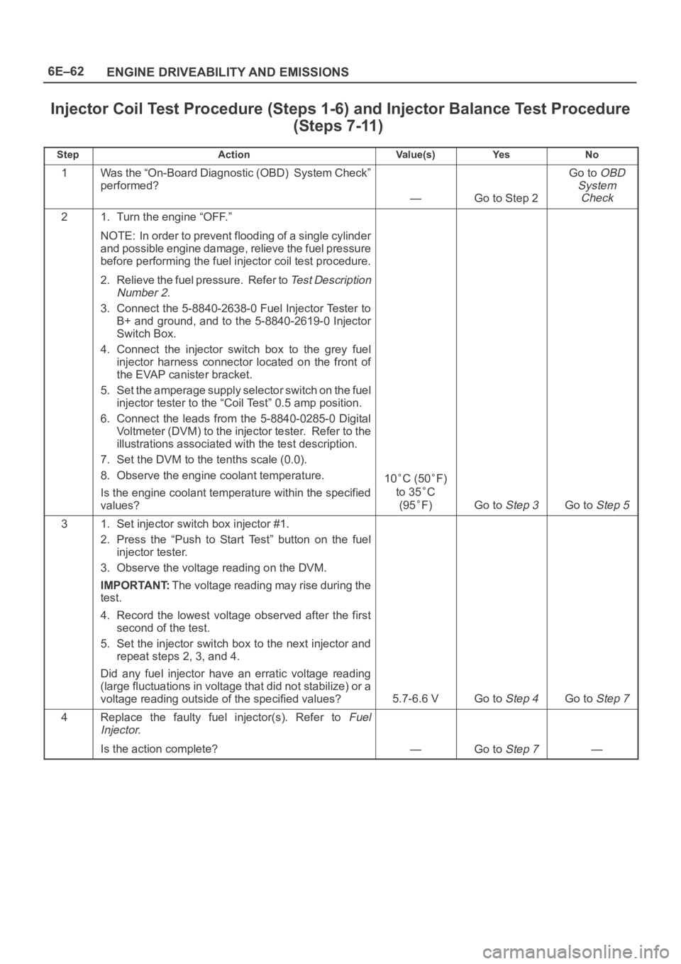
Injector Coil Test Procedure (Steps 1-6) and Injector Balance Test Procedure
(Steps 7-11)
StepActionVa l u e ( s )Ye sNo
1Was the “On-Board Diagnostic (OBD) System Check”
performed?
—Go to Step 2
Go to OBD
System
Check
21. Turn the engine “OFF.”
NOTE: In order to prevent flooding of a single cylinder
and possible engine damage, relieve the fuel pressure
before performing the fuel injector coil test procedure.
2. Relieve the fuel pressure. Refer to
Test Description
Number 2.
3. Connect the 5-8840-2638-0 Fuel Injector Tester to
B+ and ground, and to the 5-8840-2619-0 Injector
Switch Box.
4. Connect the injector switch box to the grey fuel
injector harness connector located on the front of
the EVAP canister bracket.
5. Set the amperage supply selector switch on the fuel
injector tester to the “Coil Test” 0.5 amp position.
6. Connect the leads from the 5-8840-0285-0 Digital
Voltmeter (DVM) to the injector tester. Refer to the
illustrations associated with the test description.
7. Set the DVM to the tenths scale (0.0).
8. Observe the engine coolant temperature.
Is the engine coolant temperature within the specified
values?
10C (50F)
to 35
C
(95
F)Go to Step 3Go to Step 5
31. Set injector switch box injector #1.
2. Press the “Push to Start Test” button on the fuel
injector tester.
3. Observe the voltage reading on the DVM.
IMPORTANT:The voltage reading may rise during the
test.
4. Record the lowest voltage observed after the first
second of the test.
5. Set the injector switch box to the next injector and
repeat steps 2, 3, and 4.
Did any fuel injector have an erratic voltage reading
(large fluctuations in voltage that did not stabilize) or a
voltage reading outside of the specified values?
5.7-6.6 VGo to Step 4Go to Step 7
4Replace the faulty fuel injector(s). Refer to Fuel
Injector.
Is the action complete?—Go to Step 7—
Page 1181 of 6000
6E–64
ENGINE DRIVEABILITY AND EMISSIONS
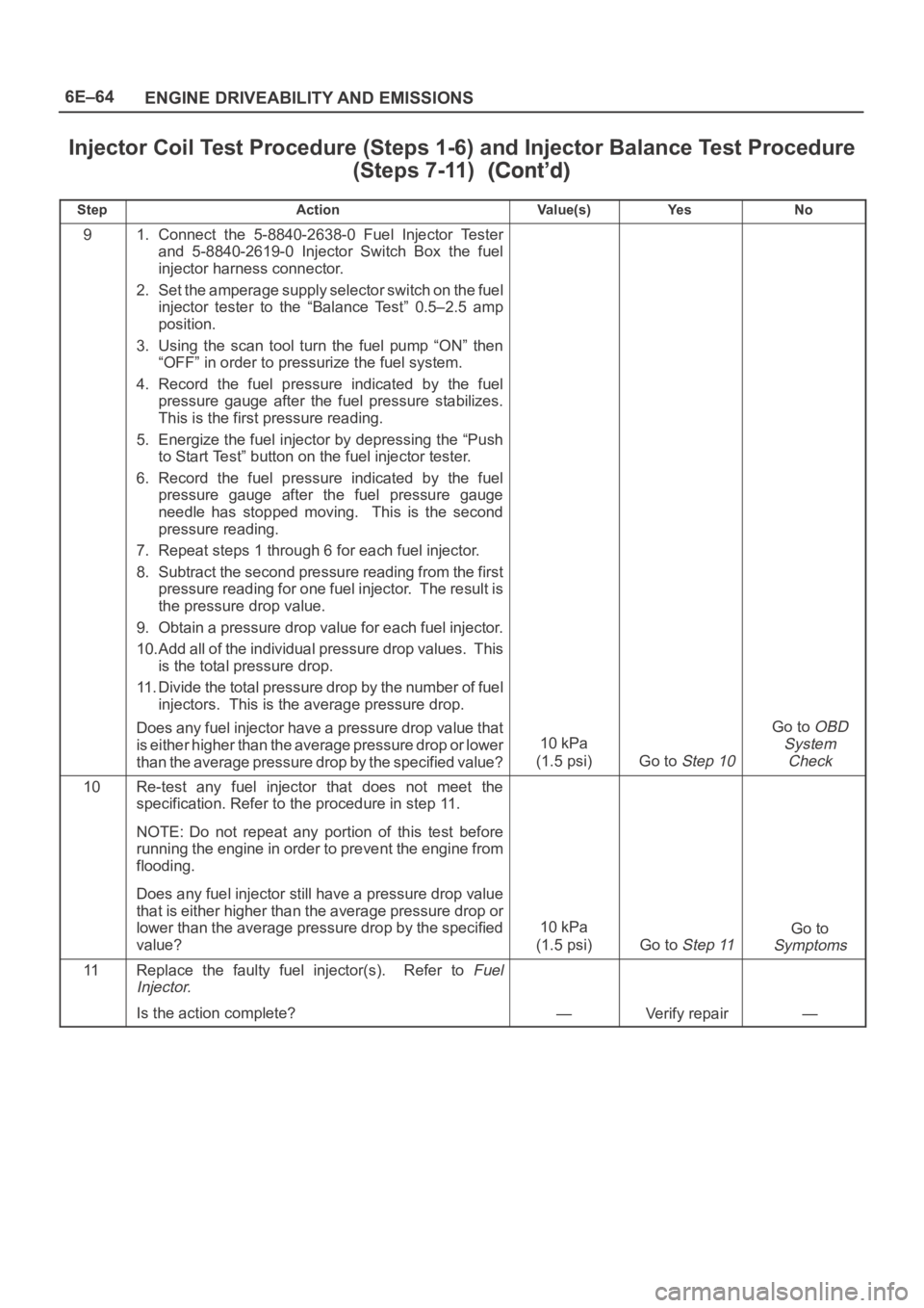
Injector Coil Test Procedure (Steps 1-6) and Injector Balance Test Procedure
(Steps 7-11)
StepNo Ye s Va l u e ( s ) Action
91. Connect the 5-8840-2638-0 Fuel Injector Tester
and 5-8840-2619-0 Injector Switch Box the fuel
injector harness connector.
2. Set the amperage supply selector switch on the fuel
injector tester to the “Balance Test” 0.5–2.5 amp
position.
3. Using the scan tool turn the fuel pump “ON” then
“OFF” in order to pressurize the fuel system.
4. Record the fuel pressure indicated by the fuel
pressure gauge after the fuel pressure stabilizes.
This is the first pressure reading.
5. Energize the fuel injector by depressing the “Push
to Start Test” button on the fuel injector tester.
6. Record the fuel pressure indicated by the fuel
pressure gauge after the fuel pressure gauge
needle has stopped moving. This is the second
pressure reading.
7. Repeat steps 1 through 6 for each fuel injector.
8. Subtract the second pressure reading from the first
pressure reading for one fuel injector. The result is
the pressure drop value.
9. Obtain a pressure drop value for each fuel injector.
10.Add all of the individual pressure drop values. This
is the total pressure drop.
11. Divide the total pressure drop by the number of fuel
injectors. This is the average pressure drop.
Does any fuel injector have a pressure drop value that
is either higher than the average pressure drop or lower
than the average pressure drop by the specified value?
10 kPa
(1.5 psi)
Go to Step 10
Go to OBD
System
Check
10Re-test any fuel injector that does not meet the
specification. Refer to the procedure in step 11.
NOTE: Do not repeat any portion of this test before
running the engine in order to prevent the engine from
flooding.
Does any fuel injector still have a pressure drop value
that is either higher than the average pressure drop or
lower than the average pressure drop by the specified
value?
10 kPa
(1.5 psi)
Go to Step 11
Go to
Symptoms
11Replace the faulty fuel injector(s). Refer to Fuel
Injector.
Is the action complete?—Verify repair—
Page 1184 of 6000

6E–67 ENGINE DRIVEABILITY AND EMISSIONS
Multiple PCM Information Sensor DTCs Set
StepNo Ye s Va l u e ( s ) Action
111. Disconnect the EGR valve.
2. Measure the voltage between the EGR pintle
position sensor signal circuit at the PCM harness
connector and ground.
Does the voltage measure near the specified value?
0 VGo to Step 13Go to Step 18
12Measure the voltage between the TFT sensor signal
circuit at the PCM harness connector and ground.
Does the voltage measure near the specified value?
0 VGo to Step 20Go to Step 19
13Replace the EGR valve.
Is the action complete?
—Verify repair—
14Locate and repair the short to voltage in the MAP
sensor signal circuit.
Is the action complete?
—Verify repair—
15Locate and repair the short to voltage in the TP sensor
signal circuit.
Is the action complete?
—Verify repair—
16Locate and repair the short to voltage in the IAT sensor
signal circuit.
Is the action complete?
—Verify repair—
17Locate and repair the short to voltage in the ECT
sensor signal circuit.
Is the action complete?
—Verify repair—
18Locate and repair the short to voltage in the EGR pintle
position sensor signal circuit.
Is the action complete?
—Verify repair—
19Locate and repair the short to voltage in the TFT sensor
signal circuit.
Is the action complete?
—Verify repair—
20Replace the PCM.
IMPORTANT:The replacement PCM must be
programmed. Refer to
UBS 98model year Immobilizer
Workshop Manual.
Is the action complete?—
Go to OBD
System
Check
—
Page 1195 of 6000
6E–78
ENGINE DRIVEABILITY AND EMISSIONS
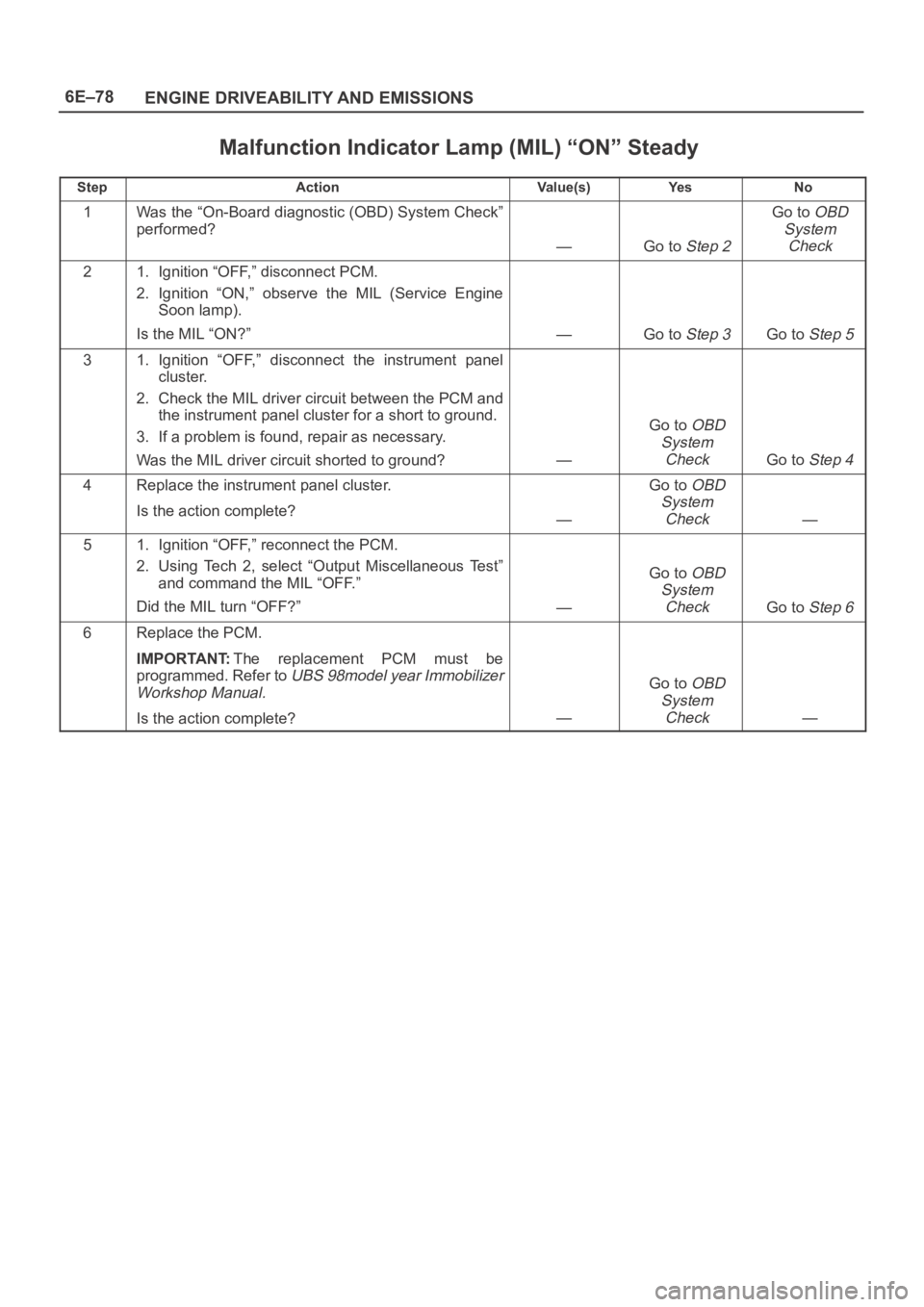
Malfunction Indicator Lamp (MIL) “ON” Steady
StepActionVa l u e ( s )Ye sNo
1Was the “On-Board diagnostic (OBD) System Check”
performed?
—Go to Step 2
Go to OBD
System
Check
21. Ignition “OFF,” disconnect PCM.
2. Ignition “ON,” observe the MIL (Service Engine
Soon lamp).
Is the MIL “ON?”
—Go to Step 3Go to Step 5
31. Ignition “OFF,” disconnect the instrument panel
cluster.
2. Check the MIL driver circuit between the PCM and
the instrument panel cluster for a short to ground.
3. If a problem is found, repair as necessary.
Was the MIL driver circuit shorted to ground?
—
Go to OBD
System
Check
Go to Step 4
4Replace the instrument panel cluster.
Is the action complete?
—
Go to OBD
System
Check
—
51. Ignition “OFF,” reconnect the PCM.
2. Using Tech 2, select “Output Miscellaneous Test”
and command the MIL “OFF.”
Did the MIL turn “OFF?”
—
Go to OBD
System
Check
Go to Step 6
6Replace the PCM.
IMPORTANT:The replacement PCM must be
programmed. Refer to
UBS 98model year Immobilizer
Workshop Manual.
Is the action complete?—
Go to OBD
System
Check
—
Page 1222 of 6000
6E–105 ENGINE DRIVEABILITY AND EMISSIONS
The engine oil dip stick not fully seated.
The engine oil fill cap loose or missing.
Test Description
Number(s) below refer to the step number(s) on the
Diagnostic Chart.
2. The MAF system performance or “rationality”
diagnostic uses the MAP sensor signal along with
other input to calculate an expected airflow rate that
is then compared to the actual measured airflow
from the MAF sensor. The first few steps of this
table verify that the MAP sensor is working properly.
6. Using Freeze Frame and/or Failure Records data
may aid in locating an intermittent condition. If the
DTC cannot be duplicated, the information included
in the Freeze Frame and/or Failure Records data
can be useful in determining how many miles since
the DTC set. The Fail Counter and Pass Counter
can also be used to determine how many ignition
cycles the diagnostic reported a pass and/or a fail.
Operate the vehicle within the same Freeze Frame
conditions (RPM, load, vehicle speed , temperature,
etc.) that were noted. This will isolate when the
DTC failed.For any test that requires back probing the PCM or
component harness connectors, use the Connector
Test Adapter Kit J 35616-A. Using this kit will
prevent any damage to the harness connector
terminals.
7. Any un-metered air may cause this DTC to set.
Check the PVC system for vacuum leaks. Also
inspect the dip stick for being pulled out. Check the
oil fill cap for being loose.
8. Verifies the signal circuit from the MAF sensor
electrical connector to the PCM.
9. Verifies whether a ground and B+ circuit is available.
10. Checks a signal circuit for an open.
11. Checks for a signal circuit shorted to B+.
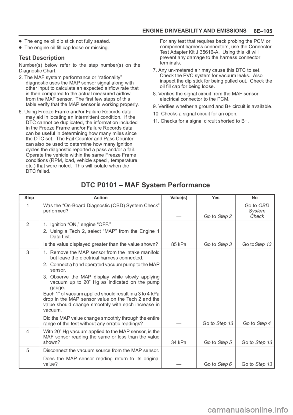
DTC P0101 – MAF System Performance
StepActionVa l u e ( s )Ye sNo
1Was the “On-Board Diagnostic (OBD) System Check”
performed?
—Go to Step 2
Go to OBD
System
Check
21. Ignition “ON,” engine “OFF.”
2. Using a Tech 2, select “MAP” from the Engine 1
Data List.
Is the value displayed greater than the value shown?
85 kPaGo to Step 3Go toStep 13
31. Remove the MAP sensor from the intake manifold
but leave the electrical harness connected.
2. Connect a hand operated vacuum pump to the MAP
sensor.
3. Observe the MAP display while slowly applying
vacuum up to 20” Hg as indicated on the pump
gauge.
Each 1” of vacuum applied should result in a 3 to 4 kPa
drop in the MAP sensor value on the Tech 2 and the
value should change smoothly with each increase in
vacuum.
Did the MAP value change smoothly through the entire
range of the test without any erratic readings?
—Go to Step 13Go to Step 4
4With 20” Hg vacuum applied to the MAP sensor, is the
MAF sensor reading the same or less than the value
shown?
34 kPaGo to Step 5Go to Step 13
5Disconnect the vacuum source from the MAP sensor.
Does the MAP sensor reading return to its original
value?
—Go to Step 6Go to Step 13
Page 1228 of 6000

6E–111 ENGINE DRIVEABILITY AND EMISSIONS
DTC P0103 – MAF Sensor Circuit High Frequency
StepActionVa l u e ( s )Ye sNo
1Was the “On-Board Diagnostic (OBD) System Check”
performed?
—Go to Step 2
Go to OBD
System
Check
21. Ignition “ON,” engine “OFF.”
2. Review and record Tech 2 Failure Records data.
3. Operate the vehicle within Failure Records
conditions as noted.
4. Using a Tech 2, monitor “DTC” info for DTC P0103.
Does the Tech 2 indicate DTC P0103 failed this
ignition?
—Go to Step 3
Refer to
Diagnostic
Aids
31. Start the engine.
2. With the engine idling, monitor “MAF Frequency”
display on the Tech 2.
Is “MAF Frequency” above the specified value?
219 g/SecGo to Step 4Go to Step 7
41. Ignition “OFF.”
2. Disconnect the MAF sensor connector.
3. Ignition “ON,” engine idling.
4. Using a Tech 2, monitor “MAF Frequency.”
Does the Tech 2 indicate a “MAF Frequency” at the
specified value?
0.0 g/SecGo to Step 5Go to Step 6
5Replace the MAF sensor.
Is the action complete?
—Verify repairGo to Step 8
61. Check the MAF harness for incorrect routing near
high voltage components (solenoids, relays,
motors).
2. If incorrect routing is found, correct the harness
routing.
Was a problem found?
—Verify repairGo to Step 7
71. With the engine idling, monitor “MAF Frequency”
display on the Tech 2.
2. Quickly snap open throttle to wide open throttle
while under a road load and record value.
Does the Tech 2 indicate “MAF Frequency” above the
specified value?
219 g/SecGo to Step 5Go to Step 8
8Replace the PCM.
IMPORTANT:The replacement PCM must be
programmed. Refer to
UBS 98model year Immobilizer
Workshop Manual.
Is the action complete?—Verify repair—
Page 1237 of 6000
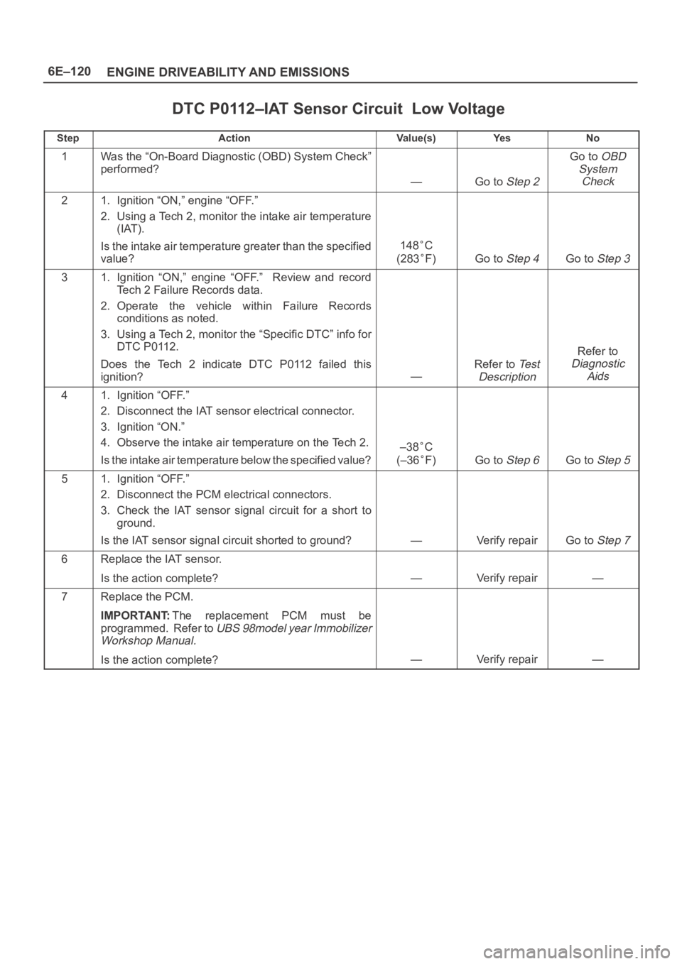
6E–120
ENGINE DRIVEABILITY AND EMISSIONS
DTC P0112–IAT Sensor Circuit Low Voltage
StepActionVa l u e ( s )Ye sNo
1Was the “On-Board Diagnostic (OBD) System Check”
performed?
—Go to Step 2
Go to OBD
System
Check
21. Ignition “ON,” engine “OFF.”
2. Using a Tech 2, monitor the intake air temperature
(IAT).
Is the intake air temperature greater than the specified
value?
148C
(283
F)Go to Step 4Go to Step 3
31. Ignition “ON,” engine “OFF.” Review and record
Tech 2 Failure Records data.
2. Operate the vehicle within Failure Records
conditions as noted.
3. Using a Tech 2, monitor the “Specific DTC” info for
DTC P0112.
Does the Tech 2 indicate DTC P0112 failed this
ignition?
—
Refer to Te s t
Description
Refer to
Diagnostic
Aids
41. Ignition “OFF.”
2. Disconnect the IAT sensor electrical connector.
3. Ignition “ON.”
4. Observe the intake air temperature on the Tech 2.
Is the intake air temperature below the specified value?
–38C
(–36
F)Go to Step 6Go to Step 5
51. Ignition “OFF.”
2. Disconnect the PCM electrical connectors.
3. Check the IAT sensor signal circuit for a short to
ground.
Is the IAT sensor signal circuit shorted to ground?
—Verify repairGo to Step 7
6Replace the IAT sensor.
Is the action complete?
—Verify repair—
7Replace the PCM.
IMPORTANT:The replacement PCM must be
programmed. Refer to
UBS 98model year Immobilizer
Workshop Manual.
Is the action complete?—Verify repair—
Page 1243 of 6000
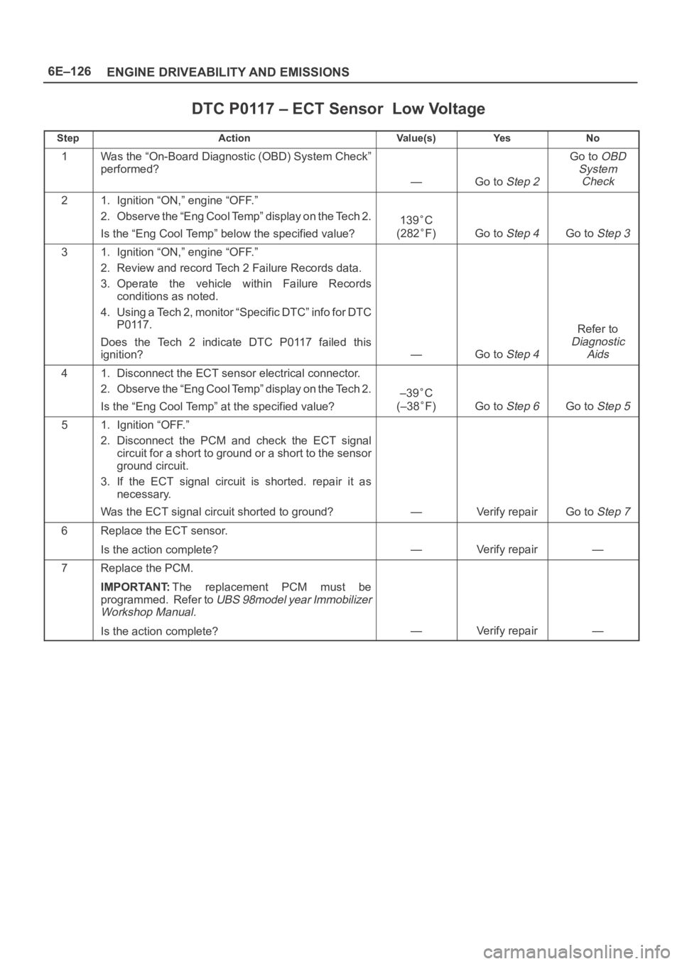
6E–126
ENGINE DRIVEABILITY AND EMISSIONS
DTC P0117 – ECT Sensor Low Voltage
StepActionVa l u e ( s )Ye sNo
1Was the “On-Board Diagnostic (OBD) System Check”
performed?
—Go to Step 2
Go to OBD
System
Check
21. Ignition “ON,” engine “OFF.”
2. Observe the “Eng Cool Temp” display on the Tech 2.
Is the “Eng Cool Temp” below the specified value?
139C
(282
F)Go to Step 4Go to Step 3
31. Ignition “ON,” engine “OFF.”
2. Review and record Tech 2 Failure Records data.
3. Operate the vehicle within Failure Records
conditions as noted.
4. Using a Tech 2, monitor “Specific DTC” info for DTC
P0117.
Does the Tech 2 indicate DTC P0117 failed this
ignition?
—Go to Step 4
Refer to
Diagnostic
Aids
41. Disconnect the ECT sensor electrical connector.
2. Observe the “Eng Cool Temp” display on the Tech 2.
Is the “Eng Cool Temp” at the specified value?
–39C
(–38
F)Go to Step 6Go to Step 5
51. Ignition “OFF.”
2. Disconnect the PCM and check the ECT signal
circuit for a short to ground or a short to the sensor
ground circuit.
3. If the ECT signal circuit is shorted. repair it as
necessary.
Was the ECT signal circuit shorted to ground?
—Verify repairGo to Step 7
6Replace the ECT sensor.
Is the action complete?
—Verify repair—
7Replace the PCM.
IMPORTANT:The replacement PCM must be
programmed. Refer to
UBS 98model year Immobilizer
Workshop Manual.
Is the action complete?—Verify repair—
Page 1257 of 6000

6E–140
ENGINE DRIVEABILITY AND EMISSIONS
HO2S, causing the system to appear lean. Check for
exhaust leaks that may cause a false lean condition to
be indicated.
MAF sensor – The system can go lean if the MAF
sensor signal indicates an engine airfiow
measurement that is not correct. Disconnect the MAF
sensor to see if the lean condition is corrected. If so,
replace the MAF sensor.
Fuel contamination – Water, even in small amounts,
can be delivered to the fuel injectors. The water can
cause a lean exhaust to be indicated. Excessive
alcohol in the fuel can also cause this condition. Refer
to
Fuel System Diagnosis for the procedure to check
for fuel contamination.
If none of the above conditions are present, replace the
affected HO2S.
Test Description
Number(s) below refer to step numbers on the diagnostic
chart.
3. DTC P0131 failing during operation may indicate a
condition described in the “Diagnostic Aids” above.
If the DTC P0131 test passes while the Failure
Records conditions are being duplicated, an
intermittent condition is indicated.
Reviewing the Failure Records vehicle mileage since the
diagnostic test last failed may help determine how often
the condition that caused the DTC to be set occurs. This
may assist in diagnosing the condition.
DTC P0131 –HO2S Circuit Low Voltage Bank 1 Sensor 1
StepActionVa l u e ( s )Ye sNo
1Was the “On-Board Diagnostic (OBD) System Check”
performed?
—Go to Step 2
Go to OBD
System
Check
21. Install the Tech 2.
2. Run the engine at operating temperature.
3. Operate the vehicle within the parameters specified
under “Conditions for Setting the DTC” criteria
included in Diagnostic Support.
4. Using a Tech 2, monitor Bank 1 HO2S 1 voltage.
Does the Bank 1 HO2S 1 voltage remain below the
specified value?
22 mVGo to Step 4Go to Step 3
31. Ignition “ON,” engine “OFF,” review and record Tech
2 Failure Records data and note parameters.
2. Operate the vehicle within Failure Records
conditions as noted.
3. Using a Tech 2, monitor “Specific DTC” info for DTC
P0131 until the DTC P0131 test runs.
Note test result.
Does Tech 2 indicate DTC P0131 failed this ignition?
—Go to Step 4
Refer to
Diagnostic
Aids
41. Turn the ignition “OFF.”
2. Disconnect the PCM.
3. Check the Bank 1 HO2S 1 high and low circuits for a
short to ground or a short to the heater ground
circuit.
Are the Bank 1 HO2S 1 signal circuits shorted to
ground?
—Go to Step 5Go to Step 6
5Repair the Bank 1 HO2S 1 signal circuit.
Is the action complete?
—Verify repair—
61. Turn the ignition “OFF,” HO2S 1 and PCM
disconnected.
2. Check for continuity between the high and low
signal circuits.
Was there continuity between the high and low circuits?
—Go to Step 7Go to Step 8
7Repair the short between the high and low circuits.
Is the action complete?
—Verify repair—