OPEL FRONTERA 1998 Workshop Manual
Manufacturer: OPEL, Model Year: 1998, Model line: FRONTERA, Model: OPEL FRONTERA 1998Pages: 6000, PDF Size: 97 MB
Page 2091 of 6000

6E–198
4JX1–TC ENGINE DRIVEABILITY AND EMISSIONS
Excess Engine Oil Consumption
StepActionVa l u e ( s )Ye sNo
1DEFINITION:
Oil consumption measured in road tests is higher than
expected.
Was OBD System check performed?
—Go to Step 2
Go to OBD
System
Check
21. Perform a bulletin research.
2. If a bulletin that addresses the symptom is found,
correct the condition as instructed in the bulletin.
Was a bulletin found?
—Verify repairGo to Step 3
31. Check if a correct engine oil is used.
2. If a problem is found, change engine oil.
Was a problem found?
—Verify repairGo to Step 4
41. Check oil pipe connections for leakage.
2. If a problem is found, repair as necessary.
Was a problem found?
—Verify repairGo to Step 5
51. Check oil seals and gaskets for leakage.
2. If a problem is found, repair as necessary.
Was a problem found?
—Verify repairGo to Step 6
61. Connect Tech 2 to the vehicle.
2. Perform RPCV test to check its function.
3. If a problem is found, repair as necessary.
Was a problem found?
—Verify repairGo to Step 7
71. Check piston ring for damage & groove wear.
2. If a problem is found, repair as necessary.
Was a problem found?
—Verify repairGo to Step 8
81. Check valve stem, valve guide and oil controller for
wear.
2. If a problem is found, repair as necessary.
Was a problem found?
—Verify repairGo to Step 9
91. Check camshaft carrier & cylinder head gaskets for
blow-by.
2. If a problem is found, repair or replace as
necessary.
Was a problem found?
—Verify repairGo to Step 10
101. Review all the diagnostic procedures in this table.
2. If all procedures have been completed and no
malfunctions have been found, review/inspect the
following:
Visual/physical check
Tech 2 data list
Freeze Frame data
All electrical connections in suspected circuits
& systems
3. If a problem is found, repair as necessary.
Was a problem found?
—Verify repair
Contact
Te c h n i c a l
Assistance
Page 2092 of 6000

6E–199 4JX1–TC ENGINE DRIVEABILITY AND EMISSIONS
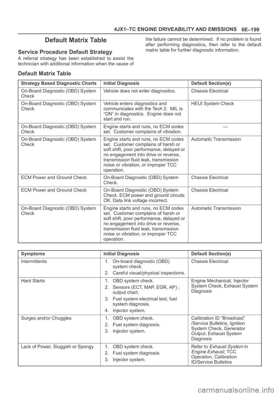
Default Matrix Table
Service Procedure Default Strategy
A referral strategy has been established to assist the
technician with additional information when the cause ofthe failure cannot be determined. If no problem is found
after performing diagnostics, then refer to the default
matrix table for further diagnostic information.
Default Matrix Table
Strategy Based Diagnostic ChartsInitial DiagnosisDefault Section(s)
On-Board Diagnostic (OBD) System
CheckVehicle does not enter diagnostics.Chassis Electrical
On-Board Diagnostic (OBD) System
CheckVehicle enters diagnostics and
communicates with the Tech 2. MIL is
“ON” in diagnostics. Engine does not
start and run.HEUI System Check
On-Board Diagnostic (OBD) System
CheckEngine starts and runs, no ECM codes
set. Customer complains of vibration.—
On-Board Diagnostic (OBD) System
CheckEngine starts and runs, no ECM codes
set. Customer complains of harsh or
soft shift, poor performance, delayed or
no engagement into drive or reverse,
transmission fluid leak, transmission
noise or vibration, or improper TCC
operation.Automatic Transmission
ECM Power and Ground CheckOn-Board Diagnostic (OBD) System
Check.Chassis Electrical
ECM Power and Ground CheckOn-Board Diagnostic (OBD) System
Check. ECM power and ground circuits
OK. Data link voltage incorrect.Chassis Electrical
On-Board Diagnostic (OBD) System
CheckEngine starts and runs, no ECM codes
set. Customer complains of harsh or
soft shift, poor performance, delayed or
no engagement into drive or reverse,
transmission fluid leak, transmission
noise or vibration, or improper TCC
operation.Automatic Transmission
SymptomsInitial DiagnosisDefault Section(s)
Intermittents1. On-board diagnostic (OBD)
system check.
2. Careful visual/physical inspections.Chassis Electrical
Hard Starts1. OBD system check.
2. Sensors (ECT, MAP, EGR, AP) ;
output chart.
3. Fuel system electrical test, fuel
system diagnosis.
4. Injector system.Engine Mechanical, Injector
System Check, Exhaust System
Diagnosis
Surges and/or Chuggles1. OBD system check.
2. Fuel system diagnosis.
3. Injector system.Calibration ID “Broadcast”
/Service Bulletins, Ignition
System Check, Generator
Output, Exhaust System
Diagnosis
Lack of Power, Sluggish or Spongy1. OBD system check.
2. Fuel system diagnosis.
3. Injector system.Refer to Exhaust System in
Engine Exhaust, TCC
Operation, Calibration
ID/Service Bulletins
Page 2093 of 6000

6E–200
4JX1–TC ENGINE DRIVEABILITY AND EMISSIONS
SymptomsInitial DiagnosisDefault Section(s)
Hesitation, Sag, Stumble1. OBD system check.
2. AP.
3. MAP output check.
4. Fuel system diagnosis.
5. Injector system.Generator Output Voltage (refer
to
Chassis Electrical),
Calibration ID/Service Bulletins,
Ignition System Check
Rough, Unstable, or Incorrect Idle,
Stalling1. OBD system check.
2. Fuel injector test.MAP Output Check, Throttle
Linkage, A/C Clutch Control
Circuit Diagnosis, Calibration
ID/Service Bulletins, Generator
Output Voltage (refer to
Chassis
Electrical
), Exhaust Diagnosis
Poor Fuel Economy1. OBD system check.
2. Careful visual/physical inspection.
3. Injector system.
4. Cooling system.TCC Operation, Exhaust
System (refer to
Engine
Exhaust
)
Engine Cranks But Will Not Run1. OBD system check.Fuel System Electrical
Diagnosis, Fuel System
Diagnosis, Fuel Injector Test.
Excessive Exhaust Emissions or
Odors1. OBD system check.
2. Emission test.
3. Cooling system.
4. Fuel system diagnosis.
5. Fuel injector test.
6. Injector system.
7. MAP output check.Exhaust Diagnosis, Calibration
ID/Service Bulletins
Dieseling, Run-On1. OBD system check.
2. Careful visual/physical inspection.
3. Fuel system diagnosis.—
Page 2094 of 6000

6E–201 4JX1–TC ENGINE DRIVEABILITY AND EMISSIONS
On–Vehicle Service
Camshaft Position (CMP)
Sensor
Removal Procedure
1. Disconnect the negative battery cable.
2. Disconnect the electrical connector to the CMP
sensor.
035RW071
3. Remove the CMP sensor retaining bolt from the
cylinder head cover.
035RW075
Inspection Procedure
1. Inspect the sensor O-ring for cracks or leaks.
2. Replace the O-ring if it is worn or damaged.
3. Lubricate the new O-ring with engine oil.
4. Install the lubricated O-ring.
Installation Procedure
1. Install the CMP sensor in the cylinder head cover.
2. Install the CMP sensor retaining bolt.
Tighten
Tighten the retaining bolt to 9 Nꞏm (78 lb in.).
035RW075
3. Connect the electrical connector to the CMP sensor.
035RW071
4. Connect the negative battery cable.
Page 2095 of 6000

6E–202
4JX1–TC ENGINE DRIVEABILITY AND EMISSIONS
Crankshaft Position (CKP)
Sensor
Removal Procedure
1. Disconnect the negative battery cable.
2. Remove the under cover.
035RW091
3. Disconnect the electrical connector to the CKP
sensor.
4. Remove one bolt and the CKP sensor from the left
side of the engine block.
NOTE: Use caution to avoid any hot oil that might drip
out.
035RW090
Inspection Procedure
1. Inspect the sensor O-ring for cracks or leaks.
2. Replace the O-ring if it is worn or damaged.
3. Lubricate the new O-ring with engine oil.
4. Install the lubricated O-ring.
Installation Procedure
1. Install the CKP sensor in the engine block.
2. Install the CKP sensor mounting bolt.
Tighten
Tighten the mounting bolt to 9 Nꞏm (78 lb in.).
035RW090
3. Connect the electrical connector to the CKP sensor.
4. Install the under cover.
035RW091
5. Connect the negative battery cable.
Page 2096 of 6000

6E–203 4JX1–TC ENGINE DRIVEABILITY AND EMISSIONS
Engine Coolant Temperature
(ECT) Sensor
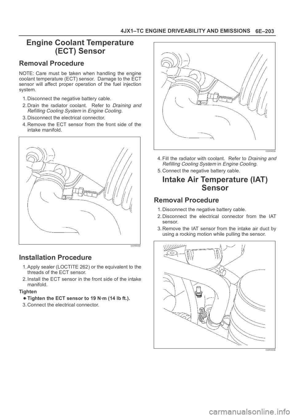
Removal Procedure
NOTE: Care must be taken when handling the engine
coolant temperature (ECT) sensor. Damage to the ECT
sensor will affect proper operation of the fuel injection
system.
1. Disconnect the negative battery cable.
2. Drain the radiator coolant. Refer to
Draining and
Refilling Cooling System
in Engine Cooling.
3. Disconnect the electrical connector.
4.Remove the ECT sensor from the front side of the
intake manifold.
035RW058
Installation Procedure
1. Apply sealer (LOCTITE 262) or the equivalent to the
threads of the ECT sensor.
2. Install the ECT sensor in the front side of the intake
manifold.
Tighten
Tighten the ECT sensor to 19 Nꞏm (14 lb ft.).
3. Connect the electrical connector.
035RW058
4. Fill the radiator with coolant. Refer to Draining and
Refilling Cooling System
in Engine Cooling.
5. Connect the negative battery cable.
Intake Air Temperature (IAT)
Sensor
Removal Procedure
1. Disconnect the negative battery cable.
2. Disconnect the electrical connector from the IAT
sensor.
3. Remove the IAT sensor from the intake air duct by
using a rocking motion while pulling the sensor.
035RW056
Page 2097 of 6000

6E–204
4JX1–TC ENGINE DRIVEABILITY AND EMISSIONS
Installation Procedure
1. Install the IAT sensor into the grommet in the intake
air duct.
035RW056
2. Correct the IAT electrical connector.
3. Connect the negative battery cable.
Manifold Absolute Pressure
(MAP) Sensor
Removal Procedure
1. Disconnect the negative battery cable.
2. Disconnect the EGR valve.
035RW054
3. Disconnect the MAP sensor connector from the MAP
sensor.
035RW053
4.Remove the bolts and the MAP sensor from the
intake manifold.
035RW057
Page 2098 of 6000

6E–205 4JX1–TC ENGINE DRIVEABILITY AND EMISSIONS
Installation Procedure
1. Install the MAP sensor and bolts on the intake
manifold.
Torque: 4 Nꞏm (35 lb in)
035RW057
2. Connect the MAP sensor connector.
035RW053
3. Connect the EGR valve.
035RW054
4. Connect the negative battery cable.
Oil Temperature (OT) Sensor
Removal Procedure
1. Disconnect the negative battery cable.
2. Remove the battery.
035RW095
Page 2099 of 6000

6E–206
4JX1–TC ENGINE DRIVEABILITY AND EMISSIONS
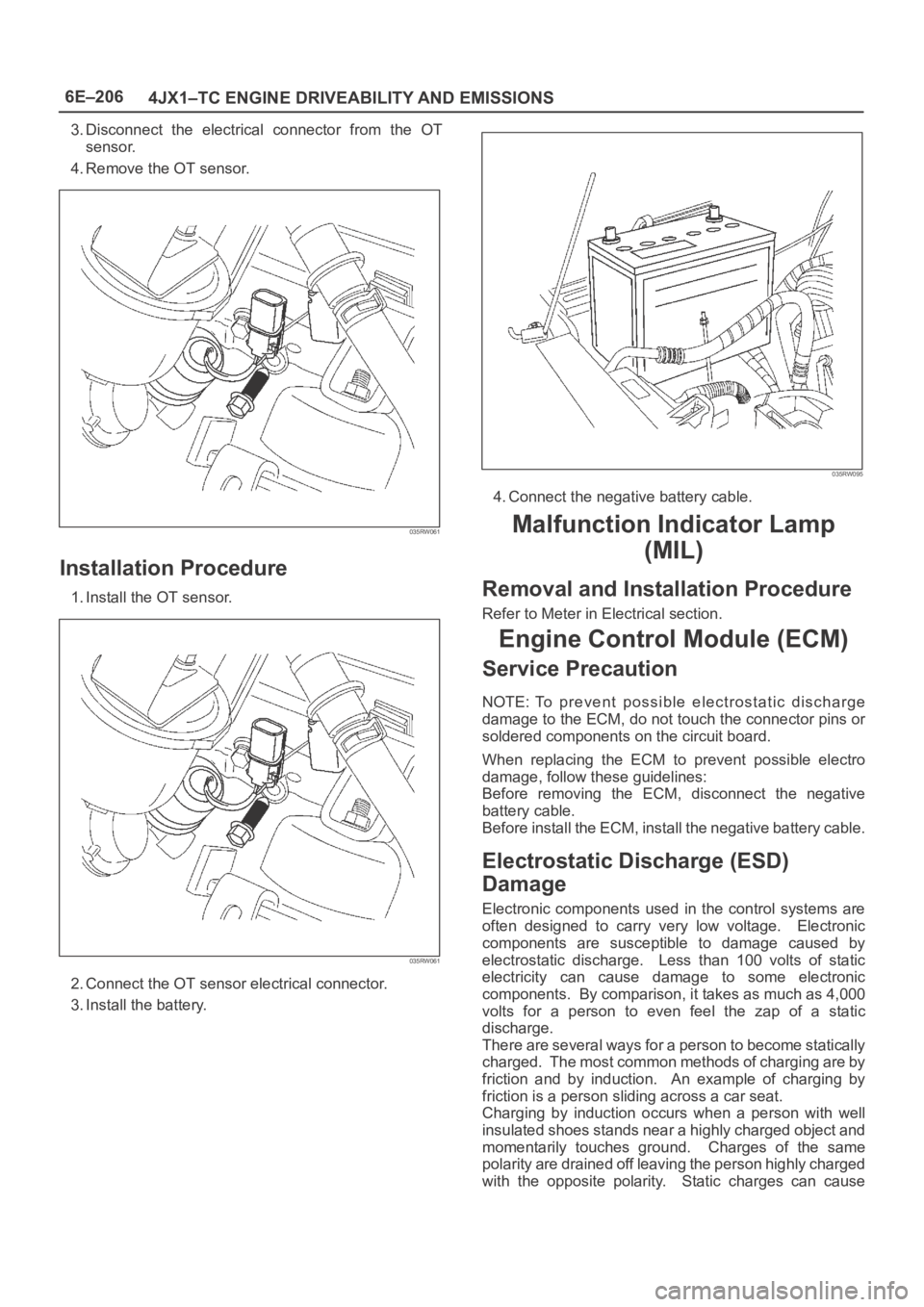
3. Disconnect the electrical connector from the OT
sensor.
4. Remove the OT sensor.
035RW061
Installation Procedure
1. Install the OT sensor.
035RW061
2. Connect the OT sensor electrical connector.
3. Install the battery.
035RW095
4. Connect the negative battery cable.
Malfunction Indicator Lamp
(MIL)
Removal and Installation Procedure
Refer to Meter in Electrical section.
Engine Control Module (ECM)
Service Precaution
NOTE: To prevent possible electrostatic discharge
damage to the ECM, do not touch the connector pins or
soldered components on the circuit board.
When replacing the ECM to prevent possible electro
damage, follow these guidelines:
Before removing the ECM, disconnect the negative
battery cable.
Before install the ECM, install the negative battery cable.
Electrostatic Discharge (ESD)
Damage
Electronic components used in the control systems are
often designed to carry very low voltage. Electronic
components are susceptible to damage caused by
electrostatic discharge. Less than 100 volts of static
electricity can cause damage to some electronic
components. By comparison, it takes as much as 4,000
volts for a person to even feel the zap of a static
discharge.
There are several ways for a person to become statically
charged. The most common methods of charging are by
friction and by induction. An example of charging by
friction is a person sliding across a car seat.
Charging by induction occurs when a person with well
insulated shoes stands near a highly charged object and
momentarily touches ground. Charges of the same
polarity are drained off leaving the person highly charged
with the opposite polarity. Static charges can cause
Page 2100 of 6000

6E–207 4JX1–TC ENGINE DRIVEABILITY AND EMISSIONS
damage, therefore, it is important to use care when
handling and testing electronic components.
NOTE: To prevent possible Electrostatic Discharge
damage, follow these guidelines:
Do not touch the control module connector pins or
soldered components on the control module circuit
board.
Do not open the replacement part package until the
part is ready to be installed.
Before removing the part from the package, ground
the package to a known good ground on the vehicle.
If the part has been handled while sliding across the
seat, or while sitting down from a standing position, or
while walking a distance, touch a known good ground
before installing the part.
NOTE: To prevent internal ECM damage, the ignition
must be in the “OFF” position in order to disconnect or
reconnect power to the ECM (for example: battery cable,
ECM pigtail, ECM fuse, jumper cables, etc.).
IMPORTANT:When replacing the production ECM
with a service ECM, it is important to transfer the
broadcast code and production ECM number to the
service ECM label. This will allow positive identification of
ECM parts throughout the service life of the vehicle. Do
not record this information on the metal ECM cover.
IMPORTANT:The ignition should always be in the
“OFF” position in order to install or remove the ECM
connectors.
Service of the ECM should normally consist of either re-
placement of the ECM. If the diagnostic procedures call
for the ECM to be replaced, the ECM should be checked
first to ensure it is the correct part. If it is, remove the
faulty ECM and install the new service ECM.
DTC P0601 indicates the check sum error.
Removal Procedure
1. Disconnect the negative battery cable.
2. Disconnect the ECM connector.
035RW093
3. Remove the bolts ECM bracket and battery bracket.
035RW094
4. Remove the ECM.
035RW092