OPEL FRONTERA 1998 Workshop Manual
Manufacturer: OPEL, Model Year: 1998, Model line: FRONTERA, Model: OPEL FRONTERA 1998Pages: 6000, PDF Size: 97 MB
Page 2171 of 6000

7A–17 AUTOMATIC TRANSMISSION (4L30–E)
Chart 7: Harsh 1–2 Shift
StepActionYe sNo
1Check line pressure. Refer to Line Pressure Test in this section.
Was line pressure normal?Check for 1–2
accumulator
valve (320) stuck
by foreign
material in main
case valve body.
Use Chart 15b:
Possible Causes
of High Line
Pressure in this
section.
Chart 8: Harsh 3–4 Shift
StepActionYe sNo
1Check line pressure. Refer to Line Pressure Test in this section.
Was line pressure normal?
Go to Step 2
Use Chart 15b:
Possible Causes
of High Line
Pressure in this
section
21. Check for 3–4 accumulator valve (407) stuck in adapter case
valve body (401).
2. Check for 3–4 accumulator piston (18) stuck in adapter case
(20).
Was the problem found?
Repair or replace—
Chart 9a: 3–2 Downshift Complaint
StepActionYe sNo
1Check line pressure. Refer to Line Pressure Test in this section.
Was line pressure normal?
Go to Step 2
Use Chart 15a:
Possible Causes
of Low Line
Pressure in this
section
2Does DTC P1850 set?
Diagnose P1850
first
Replace band
apply solenoid
(PWM) (323)
Chart 9b: Harsh Shift When Shifting Into “D” Or Accelerating From Stop
StepActionYe sNo
1Check line pressure. Refer to Line Pressure Test in this section.
Was line pressure normal?
Go to Step 2
Use Chart 15b:
Possible Causes
of High Line
Pressure in this
section
2Does DTC P1850 set?
Diagnose P1850
first
Replace band
apply solenoid
(PWM) (323)
Page 2172 of 6000

7A–18
AUTOMATIC TRANSMISSION (4L30–E)
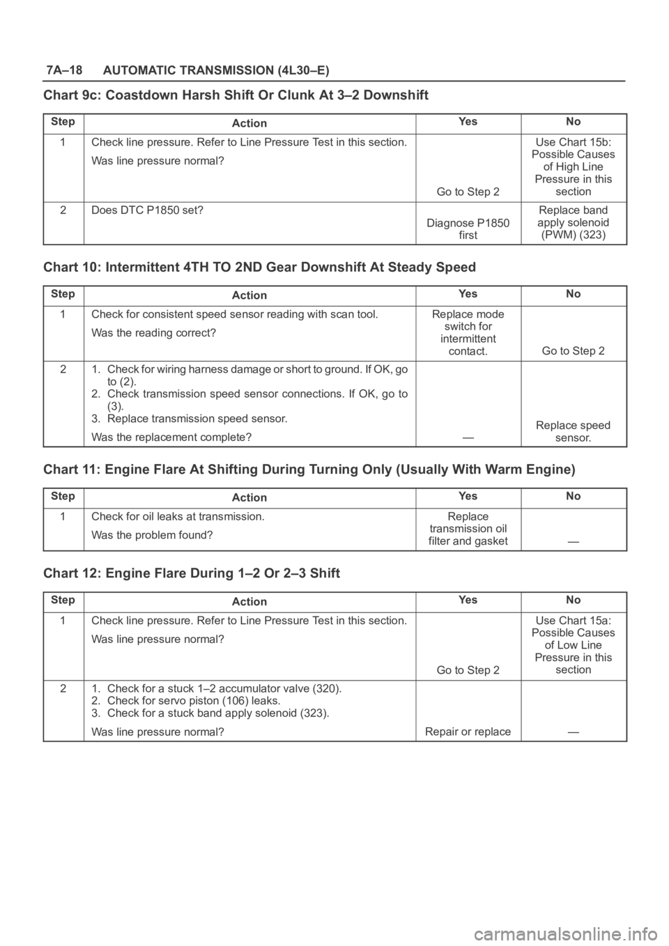
Chart 9c: Coastdown Harsh Shift Or Clunk At 3–2 Downshift
StepActionYe sNo
1Check line pressure. Refer to Line Pressure Test in this section.
Was line pressure normal?
Go to Step 2
Use Chart 15b:
Possible Causes
of High Line
Pressure in this
section
2Does DTC P1850 set?
Diagnose P1850
first
Replace band
apply solenoid
(PWM) (323)
Chart 10: Intermittent 4TH TO 2ND Gear Downshift At Steady Speed
StepActionYe sNo
1Check for consistent speed sensor reading with scan tool.
Was the reading correct?Replace mode
switch for
intermittent
contact.
Go to Step 2
21. Check for wiring harness damage or short to ground. If OK, go
to (2).
2. Check transmission speed sensor connections. If OK, go to
(3).
3. Replace transmission speed sensor.
Was the replacement complete?
—
Replace speed
sensor.
Chart 11: Engine Flare At Shifting During Turning Only (Usually With Warm Engine)
StepActionYe sNo
1Check for oil leaks at transmission.
Was the problem found?Replace
transmission oil
filter and gasket
—
Chart 12: Engine Flare During 1–2 Or 2–3 Shift
StepActionYe sNo
1Check line pressure. Refer to Line Pressure Test in this section.
Was line pressure normal?
Go to Step 2
Use Chart 15a:
Possible Causes
of Low Line
Pressure in this
section
21. Check for a stuck 1–2 accumulator valve (320).
2. Check for servo piston (106) leaks.
3. Check for a stuck band apply solenoid (323).
Was line pressure normal?
Repair or replace—
Page 2173 of 6000

7A–19 AUTOMATIC TRANSMISSION (4L30–E)
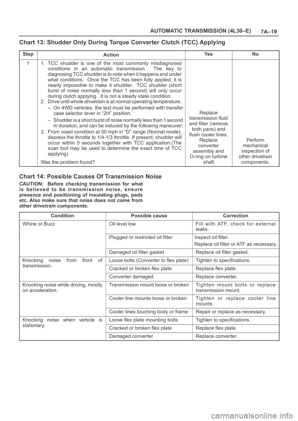
Chart 13: Shudder Only During Torque Converter Clutch (TCC) Applying
StepActionYe sNo
11. TCC shudder is one of the most commonly misdiagnosed
conditions in an automatic transmission. The key to
diagnosing TCC shudder is to note when it happens and under
what conditions. Once the TCC has been fully applied, it is
nearly impossible to make it shudder. TCC shudder (short
burst of noise normally less than 1 second) will only occur
during clutch applying. It is not a steady state condition.
2. Drive until whole drivetrain is at normal operating temperature.
– On 4WD vehicles, the test must be performed with transfer
case selector lever in “2H” position.
– Shudder is a short burst of noise normally less than 1 second
in duration, and can be induced by the following maneuver:
3. From coast condition at 50 mph in “D” range (Normal mode),
depress the throttle to 1/4-1/3 throttle. If present, shudder will
occur within 5 seconds together with TCC application.(The
scan tool may be used to determine the exact time of TCC
applying)
Was the problem found?
Replace
transmission fluid
and filter (remove
both pans) and
flush cooler lines.
Replace
converter
assembly and
O-ring on turbine
shaft
Perform
mechanical
inspection of
other drivetrain
components.
Chart 14: Possible Causes Of Transmission Noise
CAUTION: Before checking transmission for what
is believed to be transmission noise, ensure
presence and positioning of insulating plugs, pads
etc. Also make sure that noise does not come from
other drivetrain components.
Condition
Possible causeCorrection
Whine or BuzzOil level lowFill with ATF, check for external
leaks.
Plugged or restricted oil filterInspect oil filter.
Replace oil filter or ATF as necessary.
Damaged oil filter gasketReplace oil filter gasket.
Knocking noise from front of
transmission
Loose bolts (Converter to flex plate)Tighten to specifications.
transmission.Cracked or broken flex plateReplace flex plate.
Converter damagedReplace converter.
Knocking noise while driving, mostly
on acceleration.Transmission mount loose or brokenTighten mount bolts or replace
transmission mount.
Cooler line mounts loose or brokenTighten or replace cooler line
mounts.
Cooler lines touching body or frameRepair or replace as necessary.
Knocking noise when vehicle is
stationary
Loose flex plate mounting boltsTighten to specifications.
stationary.Cracked or broken flex plateReplace flex plate.
Damaged converterReplace converter.
Page 2174 of 6000

7A–20
AUTOMATIC TRANSMISSION (4L30–E)
Chart 15a: Possible Causes of Low Line Pressure
StepActionYe sNo
1Check oil level.
Was the problem found?
Fill with ATFGo to Step 2
2Check for defective throttle position sensor.
Was the problem found?Replace throttle
position sensor
Go to Step 3
3Check for plugged, loose, or damaged oil filter (79).
Was the problem found?Inspect oil filter,
tighten bolts or
replace oil filter
(79)
Go to Step 4
4Check for a stuck force motor plunger (404). (Adapter case valve
body)
Was the problem found?Replace force
motor plunger
(404)
Go to Step 5
5Check for a stuck feed limit valve (412). (Adapter case valve body)
Was the problem found?Replace feed limit
valve (412)
Go to Step 6
6Check for loose converter bolts (4 & 5).
Was the problem found?Tighten converter
bolts (4 & 5)
Go to Step 7
7Check for a stuck pressure regulator valve (208). (Oil pump)
Was the problem found?Replace pressure
regulator valve
(208)
Go to Step 8
8Check for a stuck boost valve (205).(Oil pump)
Was the problem found?Replace boost
valve (205)
Go to Step 9
9Check for blocked intermediate oil passages to pressure
regulator valve. (Oil pump)
Was the problem found?
Replace oil pumpGo to Step 10
10Check for defective oil pump (9, 201, 202 & 209).
Was the problem found?
Replace oil pumpGo to Step 11
11Check for internal leaks.
– Check balls missing or out of location in valve bodies
– Seals cut or damaged
– Gaskets defective, etc.
Was the problem found?Install balls, or
correct ball
location
Replace seals
Replace gaskets
—
Page 2175 of 6000

7A–21 AUTOMATIC TRANSMISSION (4L30–E)
Chart 15b: Possible Causes Of High Line Pressure
NOTE: If transmission is operating in backup mode, high
line pressure will be present.
Step
ActionYe sNo
1Check for defective throttle position sensor.
Was the problem found?Replace throttle
position sensor.
Go to Step 2.
2Check for a stuck force motor plunger (404). (Open
circuit/intermittent) (Adapter case valve body)
Was the problem found?Replace force
motor plunger
(404)
Go to Step 3
3Check for a stuck feed limit valve (412). (Adapter case valve body)
Was the problem found?Replace force
motor plunger
(412)
Go to Step 4
4Check converter bolts (4 & 5).
Was the problem found?Tighten converter
bolts (4 & 5)
Go to Step 5
5Check for a stuck pressure regulator valve (208). (Oil pump)
Was the problem found?Replace pressure
regulator valve
(208)
Go to Step 6
6Check for a stuck boost valve (205). (Oil pump)
Was the problem found?Replace boost
valve (205)
Go to Step 7
7Check for internal leaks.
– Check balls missing or out of location in valve bodies
– Seals cut or missing
– Gaskets defective, etc.
Was the problem found?Install balls, or
correct ball
location
Replace seals
Replace gaskets
—
Page 2176 of 6000

7A–22
AUTOMATIC TRANSMISSION (4L30–E)
Chart 16: Possible Causes Of
Transmission Fluid Leaks
Before attempting to correct an oil leak, the actual source
of the leak must be determined. In many cases, the
source of the leak may be difficult to determine due to
“wind flow” around the engine and transmission.
The suspected area should be wiped clean before in-
specting for the source of the leak.Oil leaks around the engine and transmission are gener-
ally carried toward the rear of the vehicle by the air
stream. In determining the source of an leak, the following
two checks should be made:
1. With the engine running, check for external line
pressure leaks.
2. With the engine off, check for oil leaks due to the
raised oil level caused by drainback of converter oil
into the transmission.
Possible Causes Of Fluid Leaks Due To Sealing Malfunction
240RS002
Legend
(1) Electrical Connector (Main Case) Seal
(2) Transmission Vent (Breather)
(3) Speed Sensor O–Ring
(4) Extension (Adapter) Lip Seal
(5) Extension (Adapter) to Main Case Gasket
(6) Oil Drain Plug Gasket
(7) Oil Pan Gasket (Main Case)
(8) Selector Shaft Seal(9) Oil Cooler Connectors (2)
(10) Oil Pan Gasket (Adapter Case)
(11) Converter housing attaching bolts not correctly
torqued
(12) Converter Housing Lip Seal
(13) Line Pressure Tap Plug
(14) Electrical Connector (Adapter Case) Seal
(15) Adapter Case Seal Rings (2)
Page 2177 of 6000

7A–23 AUTOMATIC TRANSMISSION (4L30–E)
Stall Test
The stall test allows you to check the transmission for
internal abrasion and the one way clutch for slippage.
Torque converter performance can also be evaluated.
The stall test results together with the road test results will
identify transmission components requiring servicing or
adjustment.
Stall Test Procedure:
1. Check the level of the engine coolant, the engine oil,
and the automatic transmission fluid. Replenish if
necessary.
2. Block the wheels and set the parking brake.
3. Connect a tachometer to the engine.
4. Start the engine and allow it to idle until the engine
coolant temperature reaches 70 – 80
C (158 –
176
F).
5. Hold the brake pedal down as far as it will go.
6. Place the selector in the “D” range.
7. Gradually push the accelerator pedal to the floor.
The throttle valve will be fully open.
Note the engine speed at which the tachometer
needle stabilizes.
Stall Speed : 2,100
150 rpm
NOTE: Do not continuously run this test longer than 5
seconds.
8. Release the accelerator pedal.
9. Place the selector in the “N” range.
10. Run the engine at 1,200 rpm for one minute.
This will cool the transmission fluid.
11. Repeat Steps 7 – 10 for the “3”, “2”, “L” and “R”
ranges.
Line Pressure Test
The line pressure test checks oil pump and control valve
pressure regulator valve function. It will also detect oil
leakage.
Line Pressure Test Procedure:
1. Check the level of the engine coolant, the engine oil,
and the automatic transmission fluid.
Replenish if required.
2. Block the wheels and set the parking brake.
3. Remove the pressure detection plug at the left side of
the transmission case.
Set 5–8840–0004–0 pressure gauge and adapter to
the pressure detection plug hole.
241RS001
4. Start the engine and allow it to idle until the engine
coolant temperature reaches 70 – 80
C (158 –
176
F).
5. Hold the brake pedal down as far as it will go.
6. Place the selector in the “D” range.
7. Note the pressure gauge reading with the engine
idling.
8. Gradually push the accelerator pedal to the floor. The
throttle valve will be fully open.
Note the pressure gauge reading with the accelerator
pedal fully depressed.
NOTE: Do not continuously run this test longer than 5
seconds.
9. Release the accelerator pedal.
10. Place the selector in the “N” range.
11. Run the engine at 1,200 rpm for one minute.
This will cool the transmission fluid.
12. Repeat Steps 7 – 11 for the “3”, “2”, “L”, and “R”
ranges.
13. Install a pressure detection plug to the transmission
case, applying recommended thread locking agent
(LOCTITE 242) or its equivalent to thread of plug.
Make sure that thread is cleaned before applying
locking agents.
14. Tighten the pressure detection plug to the specified
torque.
Torque:9–14Nꞏm(0.9–1.4kgꞏm/7–10lbft)
Page 2178 of 6000

7A–24
AUTOMATIC TRANSMISSION (4L30–E)
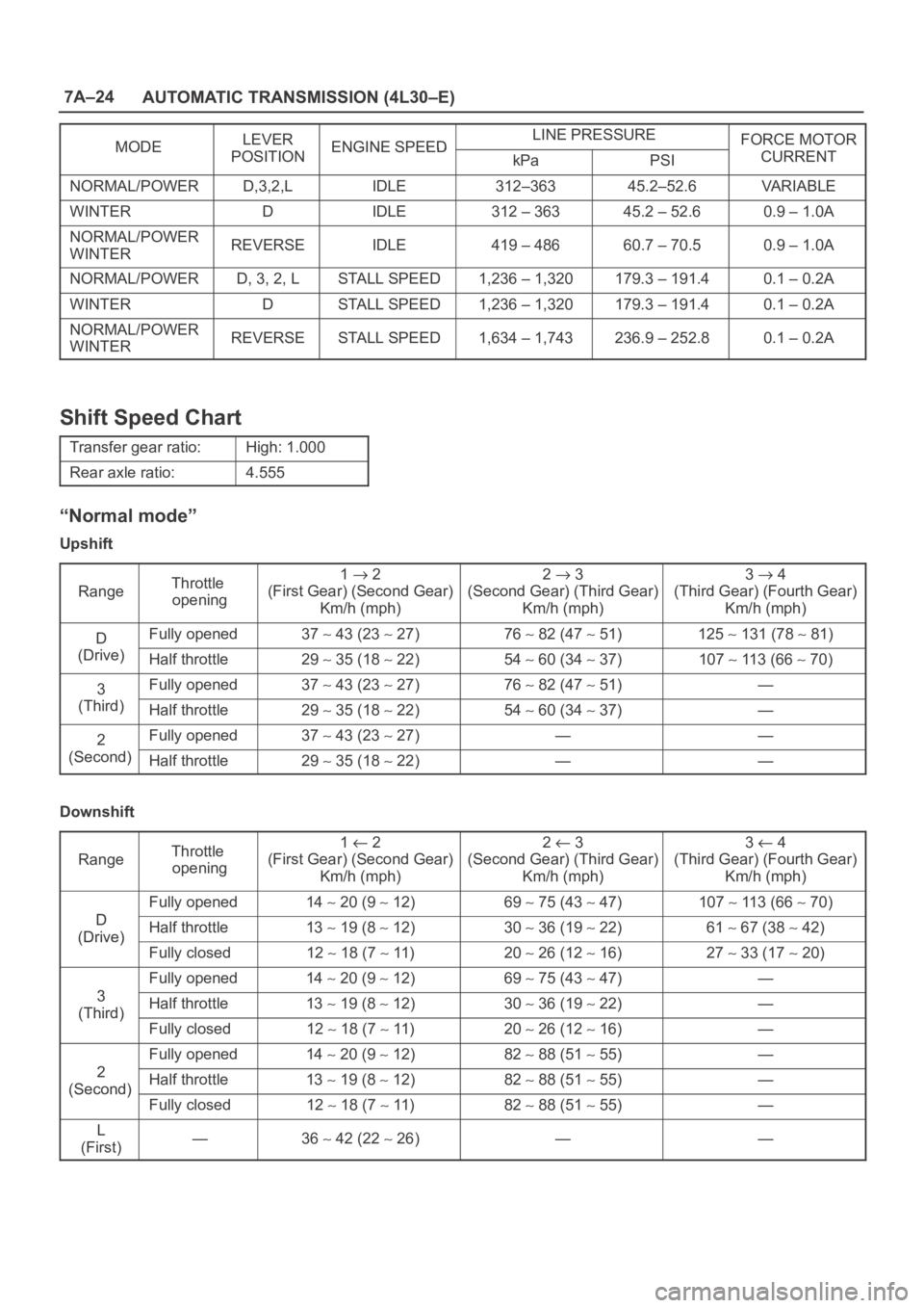
MODELEVERENGINE SPEEDLINE PRESSUREFORCE MOTORMODEPOSITIONENGINE SPEEDkPaPSICURRENT
NORMAL/POWERD,3,2,LIDLE312–36345.2–52.6VA R I A B L E
WINTERDIDLE312 – 36345.2 – 52.60.9 – 1.0A
NORMAL/POWER
WINTERREVERSEIDLE419 – 48660.7 – 70.50.9 – 1.0A
NORMAL/POWERD, 3, 2, LSTALL SPEED1,236 – 1,320179.3 – 191.40.1 – 0.2A
WINTERDSTALL SPEED1,236 – 1,320179.3 – 191.40.1 – 0.2A
NORMAL/POWER
WINTERREVERSESTALL SPEED1,634 – 1,743236.9 – 252.80.1 – 0.2A
Shift Speed Chart
Transfer gear ratio:High: 1.000
Rear axle ratio:4.555
“Normal mode”
Upshift
Range
Throttle
opening1 2
(First Gear) (Second Gear)
Km/h (mph)2 3
(Second Gear) (Third Gear)
Km/h (mph)3 4
(Third Gear) (Fourth Gear)
Km/h (mph)
DFully opened37 43 (23 27)76 82 (47 51)125 131 (78 81)
(Drive)Half throttle29 35 (18 22)54 60 (34 37)107 113 (66 70)
3Fully opened37 43 (23 27)76 82 (47 51)—
(Third)Half throttle29 35 (18 22)54 60 (34 37)—
2Fully opened37 43 (23 27)——
(Second)Half throttle29 35 (18 22)——
Downshift
Range
Throttle
opening1 2
(First Gear) (Second Gear)
Km/h (mph)2 3
(Second Gear) (Third Gear)
Km/h (mph)3 4
(Third Gear) (Fourth Gear)
Km/h (mph)
D
Fully opened14 20 (9 12)69 75 (43 47)107 113 (66 70)
D
(Drive)Half throttle13 19 (8 12)30 36 (19 22)61 67 (38 42)(Drive)
Fully closed12 18 (7 11)20 26 (12 16)27 33 (17 20)
3
Fully opened14 20 (9 12)69 75 (43 47)—
3
(Third)Half throttle13 19 (8 12)30 36 (19 22)—(Third)
Fully closed12 18 (7 11)20 26 (12 16)—
2
Fully opened14 20 (9 12)82 88 (51 55)—
2
(Second)Half throttle13 19 (8 12)82 88 (51 55)—(Second)
Fully closed12 18 (7 11)82 88 (51 55)—
L
(First)—36 42 (22 26)——
Page 2179 of 6000

7A–25 AUTOMATIC TRANSMISSION (4L30–E)
“Power mode”
Upshift
Range
Throttle
opening1 2
(First Gear) (Second Gear)
Km/h (mph)2 3
(Second Gear) (Third Gear)
Km/h (mph)3 4
(Third Gear) (Fourth Gear)
Km/h (mph)
DFully opened41 47 (25 29)79 85 (49 53)125 131 (78 81)
(Drive)Half throttle36 42 (22 26)69 75 (43 47)11 9 125 (74 78)
3Fully opened41 47 (25 29)79 85 (49 53)—
(Third)Half throttle36 42 (22 26)69 75 (43 47)—
2Fully opened41 47 (25 29)——
(Second)Half throttle36 42 (22 26)——
Downshift
Range
Throttle
opening1 2
(First Gear) (Second Gear)
Km/h (mph)2 3
(Second Gear) (Third Gear)
Km/h (mph)3 4
(Third Gear) (Fourth Gear)
Km/h (mph)
D
Fully opened28 34 (17 21)70 76 (43 47)11 5 121 (71 75)
D
(Drive)Half throttle20 26 (12 16)46 52 (29 32)90 96 (56 60)(Drive)
Fully closed12 18 (7 11)22 28 (14 17)43 50 (27 31)
3
Fully opened28 34 (17 21)70 76 (43 47)—
3
(Third)Half throttle20 26 (12 16)46 52 (29 32)—(Third)
Fully closed12 18 (7 11)22 28 (14 17)—
2
Fully opened28 34 (17 21)82 88 (51 55)—
2
(Second)Half throttle20 26 (12 16)82 88 (51 55)—(Second)
Fully closed12 18 (7 11)82 88 (51 55)—
L
(First)—36 42 (22 26)——
“Winter mode”
D range, winter mode ON OFF27 33 Km/h (17 20 mph)
Page 2180 of 6000

7A–26
AUTOMATIC TRANSMISSION (4L30–E)
Lockup Speed Chart
Transfer gear ratio:High: 1.000
Rear axle ratio:4.555
Lockup ONLockup OFF
D range Throttle
i6%
Mode2nd
Km/h
(mph)3rd
Km/h
(mph)4th
Km/h
(mph)2nd
Km/h
(mph)3rd
Km/h
(mph)4th
Km/h
(mph)
opening 6%Normal69 75
(43
47)
63 69
(39
43)
70 76
(43
47)
64 70
(40
43)
43 49
(27
30)
65 71
(40
44)
Power69 75
(43
47)
73 79
(45
49)
73 79
(45
49)
64 70
(40
43)
65 71
(40
44)
69 75
(43
47)