Gas OPEL FRONTERA 1998 Owner's Manual
[x] Cancel search | Manufacturer: OPEL, Model Year: 1998, Model line: FRONTERA, Model: OPEL FRONTERA 1998Pages: 6000, PDF Size: 97 MB
Page 683 of 6000

4C–17 DRIVE SHAFT SYSTEM
11. Install follower to clutch so that follower nails (large)
(1) will come closer to the bent portion of retaining
spring by aligning follower stopper nail with outer
teeth of clutch. Then, fit in with follower’s nails (small)
(2) caught in spring.
411RW016
12. Install compression ring.
Turn the smaller diameter side toward follower and fit
spring in clutch.
13. Align follower nail (1) to handle groove (2). and then
assemble clutch with knob by pushing and turning
clutch counterclockwise to knob.
411RW017
14. Install gasket.
Make sure that there is no breakage, etc.
15. Install outer bearing outer race by driving it into the
hub, by using installer 5–8522–2118–0 and grip
5–8840–0007–0.
411RW007
16. Install inner bearing outer race by driving it into the
hub, by using installer 5–8840–2119–0 and grip
5–8840–0007–0.
411RW006
Page 694 of 6000

4C–28
DRIVE SHAFT SYSTEM
Shift On The Fly System
Shift On The Fly System and Associated Parts
412RW004
Legend
(1) Filler Plug
(2) Bolt
(3) Oil Seal
(4) Snap Ring(External)
(5) Inner Shaft Bearing
(6) Snap Ring(Internal)
(7) Inner Shaft(8) Needle Bearing
(9) Clutch Gear
(10) Sleeve
(11) Housing
(12) Front Axle Drive Shaft (LH side)with Bracket
(13) Bolt
(14) Actuator Assembly
(15) Bolt
Disassembly
1. Remove filler plug and gasket, drain oil.
2. Loosen mounting bracket fitting bolts and remove
front axle drive shaft from front axle case.3. Remove Actuator Assembly and draw out actuator
ASM.
4. Remove housing.
5. Remove sleeve.
6. Remove clutch gear.
Page 700 of 6000

4C–34
DRIVE SHAFT SYSTEM
NOTE: Be careful not to damage seal.
6. Install snap ring (internal) in the groove of front axle
case.
NOTE: Be sure to install the snap ring properly.
412RW017
7. Apply differential gear oil to clutch gear, then install
clutch gear.
8. Apply differential gear oil to sleeve, then install
sleeve.
9. Clean contact surface with the front axle and actuator
mounting surface. Apply liquid gasket to the contact
surface on the front axle case, then install in the
housing.
412RW023
10. Tighten bolts to specified torque.
Torque: 116Nꞏm (11.8 kgꞏm/85 lb ft)11. Clean the actuator contact surface with the housing
then Install and tighten shift position switch to
specified torque.
Torque: 39Nꞏm (4.0 kgꞏm/29 lb ft)
12. Apply liquid gasket to the contact surface on the
actuator side.
412RW012
13. Align shift arm with the groove of sleeve and install the
actuator.
14. Tighten bolts to specified torque.
Torque: 13Nꞏm (1.3 kgꞏm/113 lb in)
15. Install front axle drive shaft and mounting bracket.
Tighten fitting bolts to specified torque.
Torque: 116Nꞏm (11.8 kgꞏm/85 lb ft)
16. Pour specified amount of differential gear oil to filler
plug.
Front Differential
Oil Capacity: 1.4lit (1.23 Imp qt/1.48 US qt)
Actuator Housing
Oil Capacity: 0.12lit (0.10 Imp qt/0.13 US qt)
17. Install filler plug through gasket and tighten to
specified torque.
To r q u e : 7 8 N ꞏm ( 5 8 l b f t )
Page 734 of 6000

TRANSFER CASE (STANDARD TYPE)
4D1–13
10. Offset the actuator assembly.
220RW028
11. Remove the actuator assembly.
220RW029
Legend
(7) Position: 4WD
(8) Mode: 2WD
12. Remove the transfer rear cover assembly from the
transfer case assembly.
Installation
1. Apply the recommended liquid gasket (LOCTITE
17430) or its equivalent to the transfer rear cover
fitting faces.
220RS017
2. Install the transfer rear cover assembly to the transfer
case assembly.
3. Perform the following steps before fitting the transfer
rear case:
1. Shift the high–low shift rod to the 4H side.
2. The cut–away portion of the select rod head (9)
should align with that of the rear case hole’s
stopper (10).
230RW004
4. Tighten the transfer rear case bolts to the specified
torque.
Torque: 37 Nꞏm (3.8kgꞏm/27 lb ft)
5. Shift the 2WD–4WD shift rod (11) to the 4WD side.
Page 741 of 6000

4D1–20
TRANSFER CASE (STANDARD TYPE)
Removal
1. Remove the speedometer sensor.
2. Remove the plate.
3. Remove the speedometer driven gear bushing and
driven gear.
NOTE: Apply a reference mark to the driven gear bushing
before removal.
4. Remove the front companion flange and the rear
companion flange, using the flange companion holder
5–8840–0133–0 (J–8614–11) to remove the end
nuts.
262RW067
NOTE: Use a universal puller to remove the rear
companion flange.
5. Disconnect the transfer breather hose from the
control box.
6. Remove the control box assembly.
7. Remove the transfer rear cover assembly from the
transfer case assembly.
Installation
1. Apply the recommended liquid gasket (LOCTITE
17430) or its equivalent to the transfer rear cover
fitting faces.
220RS017
2. Install the transfer rear cover assembly to the transfer
case assembly.
3. Perform the following steps before fitting the transfer
rear case:
1. Shift the high–low shift rod to the 4H side.
2. Turn the select rod counterclockwise so that the
select block projection may enter into the
2WD–4WD shift block.
3. The cut–away portion of the select rod head (9)
should align with that of the rear case hole’s
stopper (10).
230RW004
4. Tighten the transfer rear case bolts to the specified
torque.
Torque: 37 Nꞏm (3.8kgꞏm/27 lb ft)
Page 749 of 6000

4D1–28
TRANSFER CASE (STANDARD TYPE)
Inspection and Repair
Refer to “TRANSFER CASE ASSEMBLY” in this section
for inspection and repair.
Reassembly
1. Place the shift block (15) in the transfer case (16).
2. Set the shift arm (14) on the High–Low sleeve.
3. Push the High–Low shift rod (13) through the shift
arm (14) and block (14).
4. Engage the High–Low sleeve with the 4H (1) side.
5. Install the spring pins (12) to the shift block (15) and
shift arm (14).
262RW012
6 . I n s t a l l t h e s e l e c t r o d a s s e m b l y ( 11 ) , j o i n i n g i t s l e v e r t o
the shift block groove.
7. Engage the High–Low sleeve with the 4H side and
install the the interlock pin (9) and spring (10) in the
proper direction.
8. Place the 2WD–4WD shift block (7) in the transfer
case (16).
9. Set the 2WD–4WD shift arm (6) on the 2WD–4WD
sleeve.
10. Push the 2WD–4WD shift rod (5) through the
2WD–4WD shift arm (6) and 2WD–4WD shift block
(7).
11. Install the 2WD–4WD shift rod (5) with the interlock
pin pushed in.
262RW035
Legend
(18) 2WD–4WD
(19) 4H Side
(20) Interlock pin
(21) 2WD
(22) 4WD
(23) Rod: 2–4
(24) Rod: H–L
(25) 4H
(26) 4L
(27) 4
2
(28) 4
4
12. Install the 4WD indicator switch and gasket (8).
Tighten to the specified torque.
Torque: 39 Nꞏm (4.0kgꞏm/29 lb ft)
13. Install the spring (4).
Page 777 of 6000

4D2–10
TRANSFER CASE (TOD)
6. Remove the offset lever set bolt on the right side.
261RW015
7. Remove the offset lever lock spring pin.
NOTE: When removing the spring pin, note the recess
position of the pin.
261RW016
8. Remove the offset lever.
261RW017
9. Remove the sixteen bolts and detach the transfer
cover assembly from the transfer case assembly.
NOTE: When removing the transfer cover assembly, be
careful not to damage the oil seal.
Reassembly
1. Apply liquid gasket (Loctite 598 or equivalent)
uniformly to the mating face that contacts the transfer
case.
261RW023
Page 961 of 6000

6A–5
ENGINE MECHANICAL
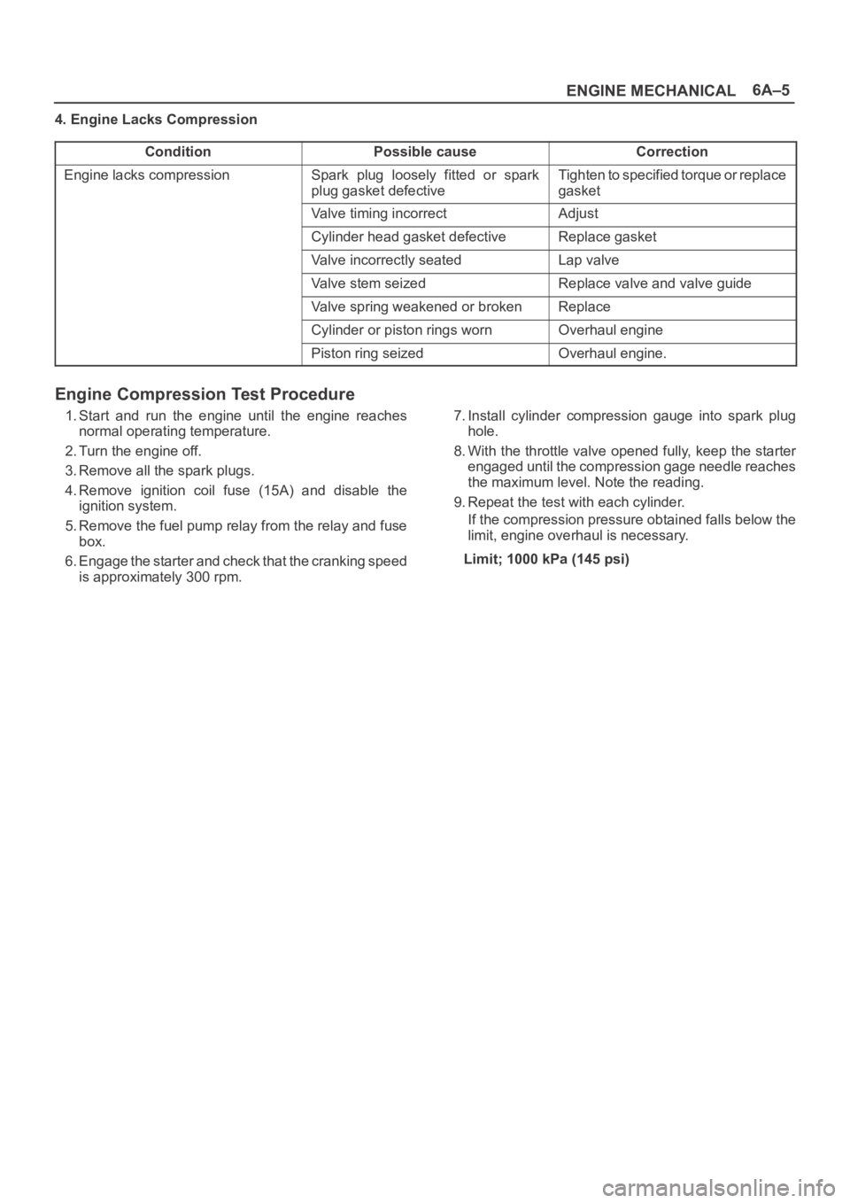
4. Engine Lacks Compression
Condition
Possible causeCorrection
Engine lacks compressionSpark plug loosely fitted or spark
plug gasket defectiveTighten to specified torque or replace
gasket
Valve timing incorrectAdjust
Cylinder head gasket defectiveReplace gasket
Valve incorrectly seatedLap valve
Valve stem seizedReplace valve and valve guide
Valve spring weakened or brokenReplace
Cylinder or piston rings wornOverhaul engine
Piston ring seizedOverhaul engine.
Engine Compression Test Procedure
1. Start and run the engine until the engine reaches
normal operating temperature.
2. Turn the engine off.
3. Remove all the spark plugs.
4. Remove ignition coil fuse (15A) and disable the
ignition system.
5. Remove the fuel pump relay from the relay and fuse
box.
6. Engage the starter and check that the cranking speed
is approximately 300 rpm.7. Install cylinder compression gauge into spark plug
hole.
8. With the throttle valve opened fully, keep the starter
engaged until the compression gage needle reaches
the maximum level. Note the reading.
9. Repeat the test with each cylinder.
If the compression pressure obtained falls below the
limit, engine overhaul is necessary.
Limit; 1000 kPa (145 psi)
Page 962 of 6000

6A–6
ENGINE MECHANICAL
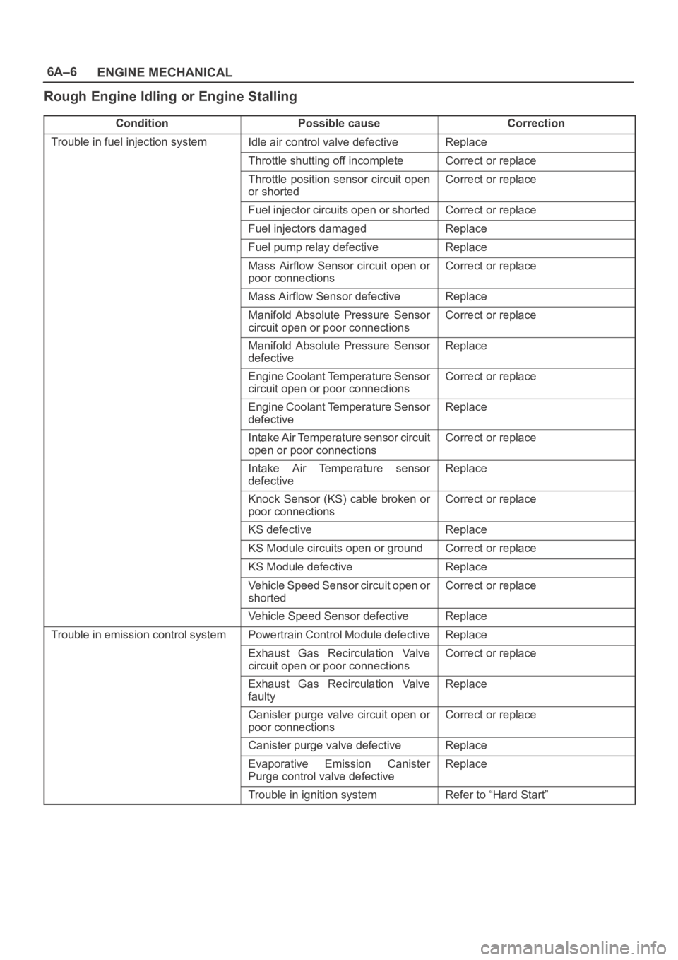
Rough Engine Idling or Engine Stalling
ConditionPossible causeCorrection
Trouble in fuel injection systemIdle air control valve defectiveReplace
Throttle shutting off incompleteCorrect or replace
Throttle position sensor circuit open
or shortedCorrect or replace
Fuel injector circuits open or shortedCorrect or replace
Fuel injectors damagedReplace
Fuel pump relay defectiveReplace
Mass Airflow Sensor circuit open or
poor connectionsCorrect or replace
Mass Airflow Sensor defectiveReplace
Manifold Absolute Pressure Sensor
circuit open or poor connectionsCorrect or replace
Manifold Absolute Pressure Sensor
defectiveReplace
Engine Coolant Temperature Sensor
circuit open or poor connectionsCorrect or replace
Engine Coolant Temperature Sensor
defectiveReplace
Intake Air Temperature sensor circuit
open or poor connectionsCorrect or replace
Intake Air Temperature sensor
defectiveReplace
Knock Sensor (KS) cable broken or
poor connectionsCorrect or replace
KS defectiveReplace
KS Module circuits open or groundCorrect or replace
KS Module defectiveReplace
Vehicle Speed Sensor circuit open or
shortedCorrect or replace
Vehicle Speed Sensor defectiveReplace
Trouble in emission control systemPowertrain Control Module defectiveReplace
Exhaust Gas Recirculation Valve
circuit open or poor connectionsCorrect or replace
Exhaust Gas Recirculation Valve
faultyReplace
Canister purge valve circuit open or
poor connectionsCorrect or replace
Canister purge valve defectiveReplace
Evaporative Emission Canister
Purge control valve defectiveReplace
Trouble in ignition systemRefer to “Hard Start”
Page 967 of 6000

6A–11
ENGINE MECHANICAL
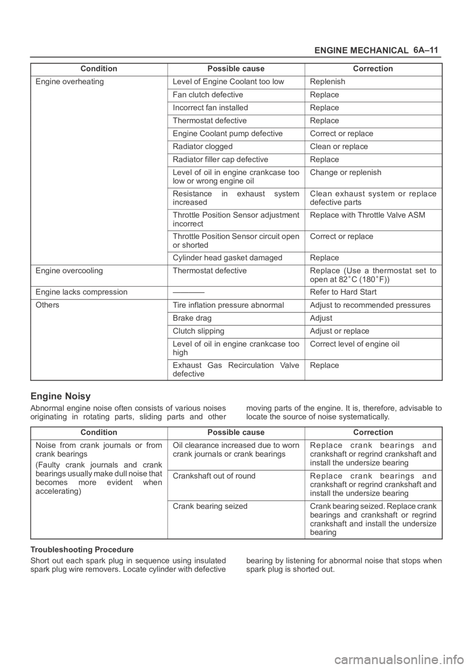
Condition CorrectionPossible cause
Engine overheatingLevel of Engine Coolant too lowReplenish
Fan clutch defectiveReplace
Incorrect fan installedReplace
Thermostat defectiveReplace
Engine Coolant pump defectiveCorrect or replace
Radiator cloggedClean or replace
Radiator filler cap defectiveReplace
Level of oil in engine crankcase too
low or wrong engine oilChange or replenish
Resistance in exhaust system
increasedClean exhaust system or replace
defective parts
Throttle Position Sensor adjustment
incorrectReplace with Throttle Valve ASM
Throttle Position Sensor circuit open
or shortedCorrect or replace
Cylinder head gasket damagedReplace
Engine overcoolingThermostat defectiveReplace (Use a thermostat set to
open at 82
C (180F))
Engine lacks compression————Refer to Hard Start
OthersTire inflation pressure abnormalAdjust to recommended pressures
Brake dragAdjust
Clutch slippingAdjust or replace
Level of oil in engine crankcase too
highCorrect level of engine oil
Exhaust Gas Recirculation Valve
defectiveReplace
Engine Noisy
Abnormal engine noise often consists of various noises
originating in rotating parts, sliding parts and othermoving parts of the engine. It is, therefore, advisable to
locate the source of noise systematically.
Condition
Possible causeCorrection
Noise from crank journals or from
crank bearings
(Faulty crank journals and crankOil clearance increased due to worn
crank journals or crank bearingsReplace crank bearings and
crankshaft or regrind crankshaft and
install the undersize bearing
yj
bearings usually make dull noise that
becomes more evident when
accelerating)Crankshaft out of roundReplace crank bearings and
crankshaft or regrind crankshaft and
install the undersize bearing
Crank bearing seizedCrank bearing seized. Replace crank
bearings and crankshaft or regrind
crankshaft and install the undersize
bearing
Troubleshooting Procedure
Short out each spark plug in sequence using insulated
spark plug wire removers. Locate cylinder with defectivebearing by listening for abnormal noise that stops when
spark plug is shorted out.