motor OPEL FRONTERA 1998 Owner's Manual
[x] Cancel search | Manufacturer: OPEL, Model Year: 1998, Model line: FRONTERA, Model: OPEL FRONTERA 1998Pages: 6000, PDF Size: 97 MB
Page 567 of 6000
4B1–34
DRIVE LINE CONTROL SYSTEM (SHIFT ON THE FLY)
4. If vacuum is not applicable as much as –400mmHg,
and if there is resistance on the intake side, replace
with a new check valve.
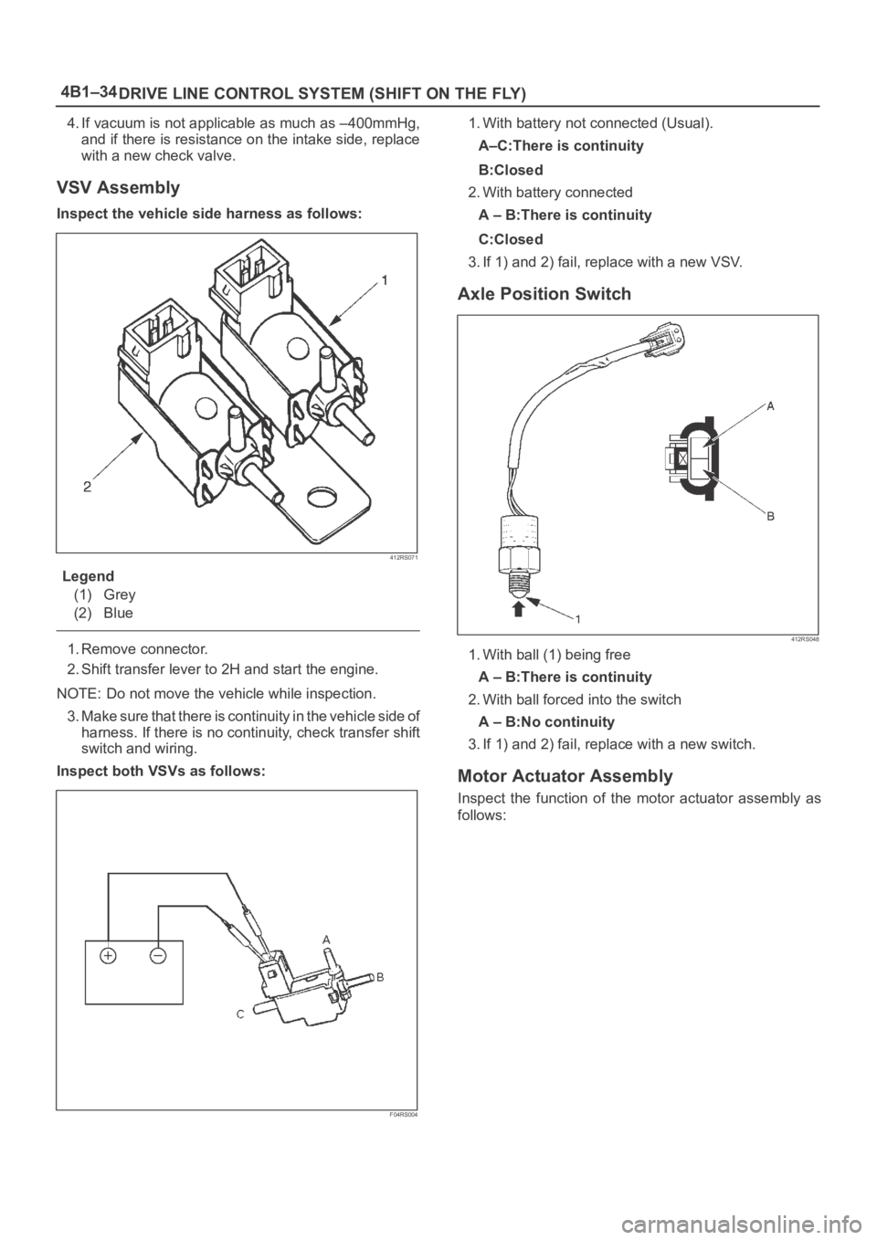
VSV Assembly
Inspect the vehicle side harness as follows:
412RS071
Legend
(1) Grey
(2) Blue
1. Remove connector.
2. Shift transfer lever to 2H and start the engine.
NOTE: Do not move the vehicle while inspection.
3. Make sure that there is continuity in the vehicle side of
harness. If there is no continuity, check transfer shift
switch and wiring.
Inspect both VSVs as follows:
F04RS004
1. With battery not connected (Usual).
A–C:There is continuity
B:Closed
2. With battery connected
A – B:There is continuity
C:Closed
3. If 1) and 2) fail, replace with a new VSV.
Axle Position Switch
412RS048
1. With ball (1) being free
A – B:There is continuity
2. With ball forced into the switch
A – B:No continuity
3. If 1) and 2) fail, replace with a new switch.
Motor Actuator Assembly
Inspect the function of the motor actuator assembly as
follows:
Page 568 of 6000

4B1–35 DRIVE LINE CONTROL SYSTEM (SHIFT ON THE FLY)
1. Disassemble the motor actuator from transfer rear
case.
412RW037
Legend
(3) Shift Rod
(4) Connector
2. Connect the terminals as shown in figure.
Shift rod of the motor actuator moves and stops
at 4WD position.
412RW038
Legend
(1) 2WD
(2) 4WD
(3) Shift Rod
(4) Connector
3. Connect the terminals as shown in figure.Shift rod of the motor actuator moves and stops
at 2WD position.
412RW039
Legend
(1) 2WD
(2) 4WD
(3) Shift Rod
(4) Connector
4. If 2) and 3) fail, replace with a new motor actuator.
Transfer Position Switch
412RW040
Legend
(1) Ball
1. With ball being free.
A–B : There is continuity.
2. With ball forced into the switch.
A–B : No continuity.
3. If 1) and 2) fail, replace with a new switch.
Page 811 of 6000

5A–1 BRAKE CONTROL SYSTEM
BRAKES
CONTENTS
Brake Control System 5A. . . . . . . . . . . . . . . . . . . .
Anti–lock Brake System 5B. . . . . . . . . . . . . . . . . . Power–Assisted Brake System 5C. . . . . . . . . . . .
Parking Brakes 5D. . . . . . . . . . . . . . . . . . . . . . . . .
BRAKE CONTROL SYSTEM
CONTENTS
Service Precaution 5A–2. . . . . . . . . . . . . . . . . . . . . .
General Description 5A–3. . . . . . . . . . . . . . . . . . . . .
System Components 5A–3. . . . . . . . . . . . . . . . . . .
Electronic Hydraulic Control Unit (EHCU) 5A–3.
ABS Warning Light 5A–4. . . . . . . . . . . . . . . . . . . .
Wheel Speed Sensor 5A–4. . . . . . . . . . . . . . . . . .
G-Sensor 5A–4. . . . . . . . . . . . . . . . . . . . . . . . . . . . .
Normal and Anti-lock Braking 5A–4. . . . . . . . . . .
Brake Pedal Travel 5A–4. . . . . . . . . . . . . . . . . . . .
Acronyms and Abbreviations 5A–4. . . . . . . . . . . .
General Diagnosis 5A–5. . . . . . . . . . . . . . . . . . . . . . .
General Information 5A–5. . . . . . . . . . . . . . . . . . . .
ABS Service Precautions 5A–5. . . . . . . . . . . . . . .
Computer System Service Precautions 5A–5. . .
General Service Precautions 5A–5. . . . . . . . . . . .
Note on Intermittents 5A–5. . . . . . . . . . . . . . . . . . .
Test Driving ABS Complaint Vehicles 5A–6. . . . .
“ABS” Warning Light 5A–6. . . . . . . . . . . . . . . . . . .
Normal Operation 5A–6. . . . . . . . . . . . . . . . . . . . .
Basic Diagnostic Flow Chart 5A–6. . . . . . . . . . . .
Basic Inspection Procedure 5A–7. . . . . . . . . . . . .
Tech 2 Scan Tool 5A–8. . . . . . . . . . . . . . . . . . . . . .
Getting Started 5A–9. . . . . . . . . . . . . . . . . . . . . . . .
Operating Procedure 5A–10. . . . . . . . . . . . . . . . . . .
Data List 5A–11. . . . . . . . . . . . . . . . . . . . . . . . . . . . .
EHCU Connector Pin-out Checks 5A–12. . . . . . . .
Circuit Diagram (LHD model / 6VD1 and
4JG2) 5A–13. . . . . . . . . . . . . . . . . . . . . . . . . . . . . . .
Circuit Diagram (LHD model / 4JG2) 5A–14. . . . .
Circuit Diagram (LHD model / 4JG2) 5A–15. . . . .
Circuit Diagram (LHD model / 6VD1) 5A–16. . . . .
Circuit Diagram (LHD model / 6VD1) 5A–17. . . . .
Connector List (LHD model) 5A–18. . . . . . . . . . . .
Part Location (LHD model) 5A–20. . . . . . . . . . . . . .
Circuit Diagram (RHD model / 6VD1 and
4JG2) 5A–21. . . . . . . . . . . . . . . . . . . . . . . . . . . . . . .
Circuit Diagram (RHD model / 4JG2) 5A–22. . . . .
Circuit Diagram (RHD model / 4JG2) 5A–23. . . . .
Circuit Diagram (RHD model / 6VD1) 5A–24. . . . .
Circuit Diagram (RHD model / 6VD1) 5A–25. . . . .
Circuit Diagram (RHD model / 6VE1 and
4JX1) 5A–26. . . . . . . . . . . . . . . . . . . . . . . . . . . . . . . . Circuit Diagram (RHD model / 4JX1) 5A–27. . . . .
Circuit Diagram (RHD model / 4JX1) 5A–28. . . . .
Circuit Diagram (RHD model / 6VE1) 5A–29. . . . .
Circuit Diagram (RHD model / 6VE1) 5A–30. . . . .
Connector List (RHD model) 5A–31. . . . . . . . . . . .
Part Location (RHD model) 5A–34. . . . . . . . . . . . .
Symptom Diagnosis 5A–35. . . . . . . . . . . . . . . . . . . . .
Chart A–1 ABS Works Frequently But
Vehicle Does Not Decelerate 5A–35. . . . . . . . . . .
Chart TA-1 ABS Works Frequently But
Vehicle Does Not Decelerate (Use
TECH 2) 5A–36. . . . . . . . . . . . . . . . . . . . . . . . . . . . .
Chart A-2 Uneven Braking Occurs While
ABS Works 5A–36. . . . . . . . . . . . . . . . . . . . . . . . . . .
Chart A-3, TA-3 The Wheels Are Locked 5A–36.
Chart A-4 Brake Pedal Feed Is Abnormal 5A–37.
Chart A-5, TA-5 Braking Sound (From
EHCU) Is Heard While Not Braking 5A–38. . . . . .
Diagnostic Trouble Codes 5A–39. . . . . . . . . . . . . . . .
Diagnosis By “ABS” Warning Light
Illumination Pattern 5A–40. . . . . . . . . . . . . . . . . . . . .
Diagnostic Trouble Codes (DTCs) 5A–40. . . . . . .
Chart B-1 With the key in the ON position
(Before starting the engine). Warning light
(W/L) is not activated. 5A–43. . . . . . . . . . . . . . . . .
Chart B-2 EHCU Abnormality (DTC 14) 5A–43. . .
Chart B-3 Power Voltage Drop (DTC 15) 5A–44. .
Chart B-4 CLASS-2 Communication Line
Abnormality (DTC 16) 5A–44. . . . . . . . . . . . . . . . .
Chart B-5 G-Sensor Circuit (DTC 21) 5A–45. . . . .
Chart B-6 Abnormal Transmission Input
(DTC 23) 5A–46. . . . . . . . . . . . . . . . . . . . . . . . . . . .
Chart B-7 Transfer Monitor (DTC 24) 5A–47. . . . .
Chart B-8 EHCU Pump Motor And Motor
Relay Circuit (DTC 32) 5A–47. . . . . . . . . . . . . . . . .
Chart B-9 EHCU Pump Valve And Valve
Relay Circuit (DTC 35) 5A–47. . . . . . . . . . . . . . . . .
Chart B-10 FL Isolation Solenoid Valve
Abnormality (DTC 41) 5A–48. . . . . . . . . . . . . . . . .
Chart B-11 FL Dump Solenoid Valve
Abnormality (DTC 42) 5A–48. . . . . . . . . . . . . . . . .
Chart B-12 FR Isolation Solenoid Valve
Abnormality (DTC 43) 5A–48. . . . . . . . . . . . . . . . .
Chart B-13 FR Dump Solenoid Valve
Abnormality (DTC 44) 5A–49. . . . . . . . . . . . . . . . .
Chart B-14 Rear Isolation Solenoid Valve
Abnormality (DTC 45) 5A–49. . . . . . . . . . . . . . . . .
Chart B-15 Rear Dump Solenoid Valve
Abnormality (DTC 46) 5A–49. . . . . . . . . . . . . . . . .
Page 814 of 6000
5A–4
BRAKE CONTROL SYSTEM
normal braking when a malfunction has occurred in the
ABS.
The EHCU has a self-diagnosing function which can
indicate faulty circuits during diagnosis.
The EHCU is mounted on the engine compartment front
right side. It consists of a Motor, Plunger Pump, Solenoid
Valves and Check Valve.
On the outside, the relay box containing a motor relay and
a valve relay is installed.
Solenoid Valves: Reduces or holds the caliper fluid
pressure for each front disc brake or both rear disc brakes
according to the signal sent from the EHCU.
Reservoir: Temporarily holds the brake fluid that returns
from the front and rear disc brake caliper so that pressure
of front disc brake caliper can be reduced smoothly.
Plunger Pump: Feeds the brake fluid held in the reservoir
to the master cylinder.
Motor: Drives the pump according to the signal from
EHCU.
Check Valve: Controls the brake fluid flow.
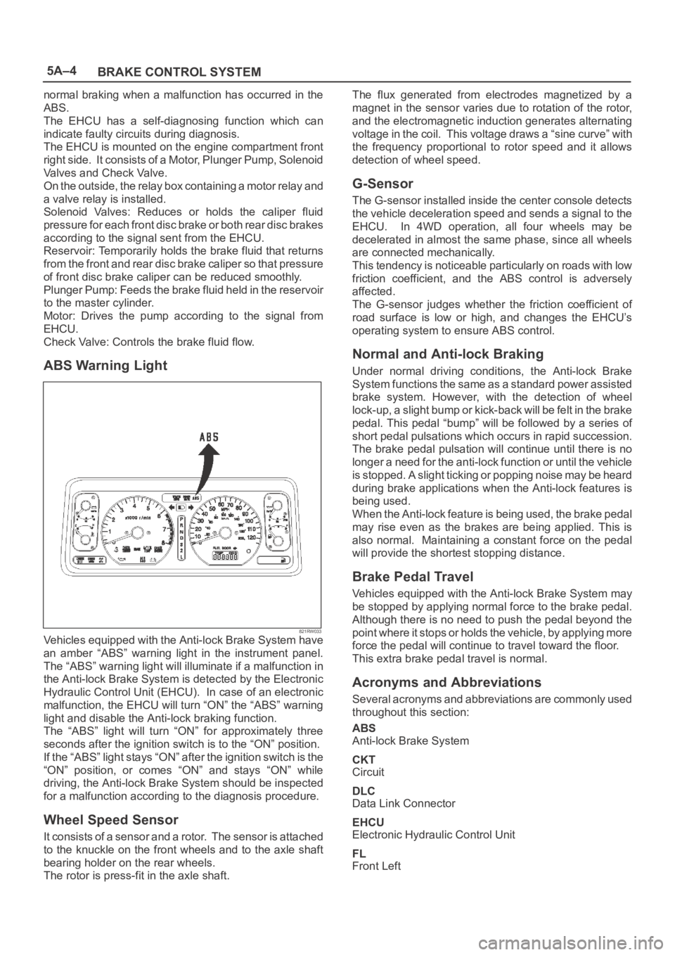
ABS Warning Light
821RW033Vehicles equipped with the Anti-lock Brake System have
an amber “ABS” warning light in the instrument panel.
The “ABS” warning light will illuminate if a malfunction in
the Anti-lock Brake System is detected by the Electronic
Hydraulic Control Unit (EHCU). In case of an electronic
malfunction, the EHCU will turn “ON” the “ABS” warning
light and disable the Anti-lock braking function.
The “ABS” light will turn “ON” for approximately three
seconds after the ignition switch is to the “ON” position.
If the “ABS” light stays “ON” after the ignition switch is the
“ON” position, or comes “ON” and stays “ON” while
driving, the Anti-lock Brake System should be inspected
for a malfunction according to the diagnosis procedure.
Wheel Speed Sensor
It consists of a sensor and a rotor. The sensor is attached
to the knuckle on the front wheels and to the axle shaft
bearing holder on the rear wheels.
The rotor is press-fit in the axle shaft.The flux generated from electrodes magnetized by a
magnet in the sensor varies due to rotation of the rotor,
and the electromagnetic induction generates alternating
voltage in the coil. This voltage draws a “sine curve” with
the frequency proportional to rotor speed and it allows
detection of wheel speed.
G-Sensor
The G-sensor installed inside the center console detects
the vehicle deceleration speed and sends a signal to the
EHCU. In 4WD operation, all four wheels may be
decelerated in almost the same phase, since all wheels
are connected mechanically.
This tendency is noticeable particularly on roads with low
friction coefficient, and the ABS control is adversely
affected.
The G-sensor judges whether the friction coefficient of
road surface is low or high, and changes the EHCU’s
operating system to ensure ABS control.
Normal and Anti-lock Braking
Under normal driving conditions, the Anti-lock Brake
System functions the same as a standard power assisted
brake system. However, with the detection of wheel
lock-up, a slight bump or kick-back will be felt in the brake
pedal. This pedal “bump” will be followed by a series of
short pedal pulsations which occurs in rapid succession.
The brake pedal pulsation will continue until there is no
longer a need for the anti-lock function or until the vehicle
is stopped. A slight ticking or popping noise may be heard
during brake applications when the Anti-lock features is
being used.
When the Anti-lock feature is being used, the brake pedal
may rise even as the brakes are being applied. This is
also normal. Maintaining a constant force on the pedal
will provide the shortest stopping distance.
Brake Pedal Travel
Vehicles equipped with the Anti-lock Brake System may
be stopped by applying normal force to the brake pedal.
Although there is no need to push the pedal beyond the
point where it stops or holds the vehicle, by applying more
force the pedal will continue to travel toward the floor.
This extra brake pedal travel is normal.
Acronyms and Abbreviations
Several acronyms and abbreviations are commonly used
throughout this section:
ABS
Anti-lock Brake System
CKT
Circuit
DLC
Data Link Connector
EHCU
Electronic Hydraulic Control Unit
FL
Front Left
Page 849 of 6000
5A–39 BRAKE CONTROL SYSTEM
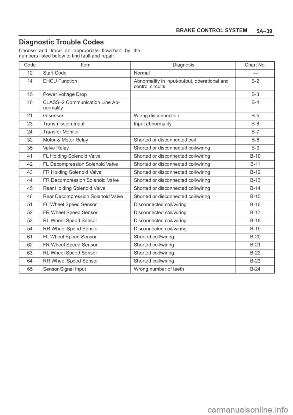
Diagnostic Trouble Codes
Choose and trace an appropriate flowchart by the
numbers listed below to find fault and repair.
Code
ItemDiagnosisChart No.
12Start CodeNormal—
14EHCU FunctionAbnormality in input/output, operational and
control circuitsB-2
15Power Voltage DropB-3
16CLASS–2 Communication Line Ab-
normalityB-4
21G-sensorWiring disconnectionB-5
23Transmission InputInput abnormalityB-6
24Transfer MonitorB-7
32Motor & Motor RelayShorted or disconnected coilB-8
35Valve RelayShorted or disconnected coil/wiringB-9
41FL Holding Solenoid ValveShorted or disconnected coil/wiringB-10
42FL Decompression Solenoid ValveShorted or disconnected coil/wiringB-11
43FR Holding Solenoid ValveShorted or disconnected coil/wiringB-12
44FR Decompression Solenoid ValveShorted or disconnected coil/wiringB-13
45Rear Holding Solenoid ValveShorted or disconnected coil/wiringB-14
46Rear Decompression Solenoid ValveShorted or disconnected coil/wiringB-15
51FL Wheel Speed SensorDisconnected coil/wiringB-16
52FR Wheel Speed SensorDisconnected coil/wiringB-17
53RL Wheel Speed SensorDisconnected coil/wiringB-18
54RR Wheel Speed SensorDisconnected coil/wiringB-19
61FL Wheel Speed SensorShorted coil/wiringB-20
62FR Wheel Speed SensorShorted coil/wiringB-21
63RL Wheel Speed SensorShorted coil/wiringB-22
64RR Wheel Speed SensorShorted coil/wiringB-23
65Sensor Signal InputWrong number of teethB-24
Page 857 of 6000
5A–47 BRAKE CONTROL SYSTEM
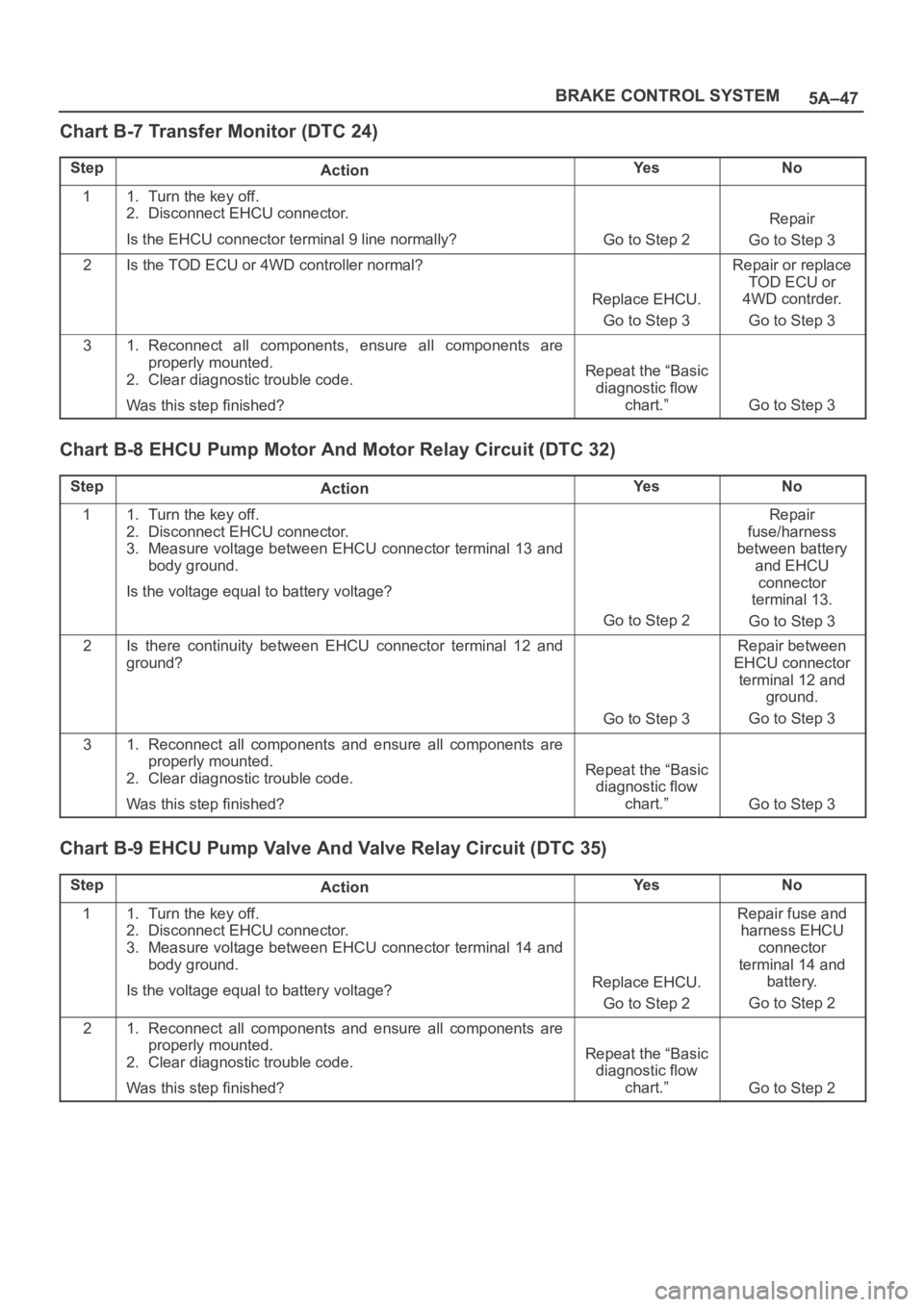
Chart B-7 Transfer Monitor (DTC 24)
StepActionYe sNo
11. Turn the key off.
2. Disconnect EHCU connector.
Is the EHCU connector terminal 9 line normally?
Go to Step 2
Repair
Go to Step 3
2Is the TOD ECU or 4WD controller normal?
Replace EHCU.
Go to Step 3
Repair or replace
TOD ECU or
4WD contrder.
Go to Step 3
31. Reconnect all components, ensure all components are
properly mounted.
2. Clear diagnostic trouble code.
Was this step finished?
Repeat the “Basic
diagnostic flow
chart.”
Go to Step 3
Chart B-8 EHCU Pump Motor And Motor Relay Circuit (DTC 32)
StepActionYe sNo
11. Turn the key off.
2. Disconnect EHCU connector.
3. Measure voltage between EHCU connector terminal 13 and
body ground.
Is the voltage equal to battery voltage?
Go to Step 2
Repair
fuse/harness
between battery
and EHCU
connector
terminal 13.
Go to Step 3
2Is there continuity between EHCU connector terminal 12 and
ground?
Go to Step 3
Repair between
EHCU connector
terminal 12 and
ground.
Go to Step 3
31. Reconnect all components and ensure all components are
properly mounted.
2. Clear diagnostic trouble code.
Was this step finished?
Repeat the “Basic
diagnostic flow
chart.”
Go to Step 3
Chart B-9 EHCU Pump Valve And Valve Relay Circuit (DTC 35)
StepActionYe sNo
11. Turn the key off.
2. Disconnect EHCU connector.
3. Measure voltage between EHCU connector terminal 14 and
body ground.
Is the voltage equal to battery voltage?
Replace EHCU.
Go to Step 2
Repair fuse and
harness EHCU
connector
terminal 14 and
battery.
Go to Step 2
21. Reconnect all components and ensure all components are
properly mounted.
2. Clear diagnostic trouble code.
Was this step finished?
Repeat the “Basic
diagnostic flow
chart.”
Go to Step 2
Page 960 of 6000
6A–4
ENGINE MECHANICAL
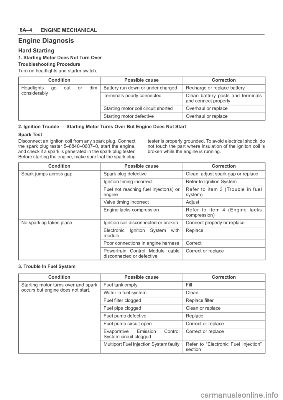
Engine Diagnosis
Hard Starting
1. Starting Motor Does Not Turn Over
Troubleshooting Procedure
Turn on headlights and starter switch.
Condition
Possible causeCorrection
Headlights go out or dim
considerably
Battery run down or under chargedRecharge or replace battery
considerablyTerminals poorly connectedClean battery posts and terminals
and connect properly
Starting motor coil circuit shortedOverhaul or replace
Starting motor defectiveOverhaul or replace
2. Ignition Trouble — Starting Motor Turns Over But Engine Does Not Start
Spark Test
Disconnect an igniton coil from any spark plug. Connect
the spark plug tester 5–8840–0607–0, start the engine,
a n d c h e c k i f a s p a r k i s g e n e r a t e d in t h e s p a r k p l u g t e s t e r.
Before starting the engine, make sure that the spark plugtester is properly grounded. To avoid electrical shock, do
not touch the part where insulation of the igniton coil is
broken while the engine is running.
Condition
Possible causeCorrection
Spark jumps across gapSpark plug defectiveClean, adjust spark gap or replace
Ignition timing incorrectRefer to Ignition System
Fuel not reaching fuel injector(s) or
engineRefer to item 3 (Trouble in fuel
system)
Valve timing incorrectAdjust
Engine lacks compressionRefer to item 4 (Engine lacks
compression)
No sparking takes placeIgnition coil disconnected or brokenConnect properly or replace
Electronic Ignition System with
moduleReplace
Poor connections in engine harnessCorrect
Powertrain Control Module cable
disconnected or defectiveCorrect or replace
3. Trouble In Fuel System
Condition
Possible causeCorrection
Starting motor turns over and spark
occurs but engine does not start
Fuel tank emptyFill
occurs but engine does not start.Water in fuel systemClean
Fuel filter cloggedReplace filter
Fuel pipe cloggedClean or replace
Fuel pump defectiveReplace
Fuel pump circuit openCorrect or replace
Evaporative Emission Control
System circuit cloggedCorrect or replace
Multiport Fuel Injection System faultyRefer to “Electronic Fuel Injection”
section
Page 1009 of 6000
6A–53
ENGINE MECHANICAL
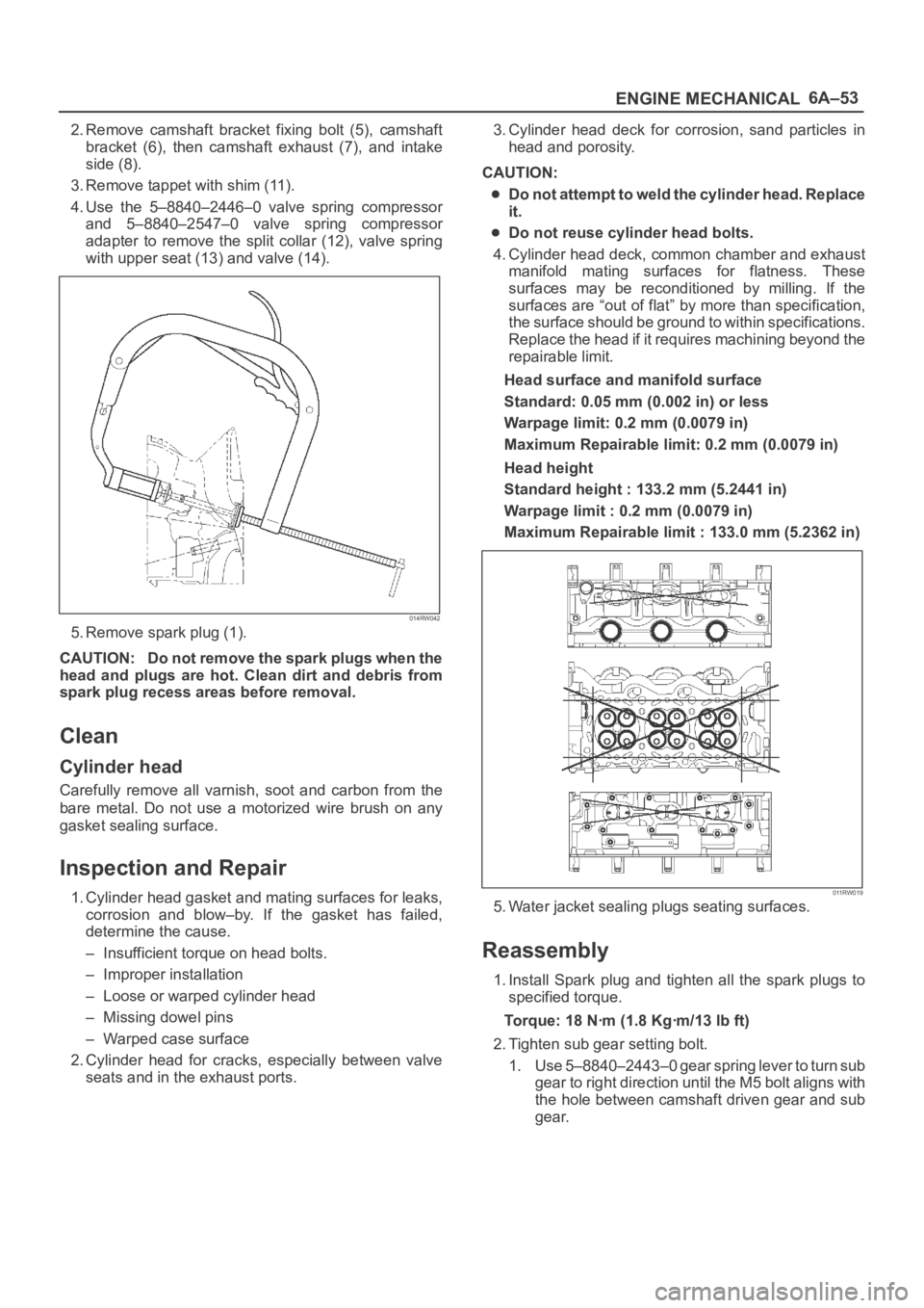
2. Remove camshaft bracket fixing bolt (5), camshaft
bracket (6), then camshaft exhaust (7), and intake
side (8).
3. Remove tappet with shim (11).
4. Use the 5–8840–2446–0 valve spring compressor
and 5–8840–2547–0 valve spring compressor
adapter to remove the split collar (12), valve spring
with upper seat (13) and valve (14).
014RW042
5. Remove spark plug (1).
CAUTION: Do not remove the spark plugs when the
head and plugs are hot. Clean dirt and debris from
spark plug recess areas before removal.
Clean
Cylinder head
Carefully remove all varnish, soot and carbon from the
bare metal. Do not use a motorized wire brush on any
gasket sealing surface.
Inspection and Repair
1. Cylinder head gasket and mating surfaces for leaks,
corrosion and blow–by. If the gasket has failed,
determine the cause.
– Insufficient torque on head bolts.
– Improper installation
– Loose or warped cylinder head
– Missing dowel pins
– Warped case surface
2. Cylinder head for cracks, especially between valve
seats and in the exhaust ports.3. Cylinder head deck for corrosion, sand particles in
head and porosity.
CAUTION:
Do not attempt to weld the cylinder head. Replace
it.
Do not reuse cylinder head bolts.
4. Cylinder head deck, common chamber and exhaust
manifold mating surfaces for flatness. These
surfaces may be reconditioned by milling. If the
surfaces are “out of flat” by more than specification,
the surface should be ground to within specifications.
Replace the head if it requires machining beyond the
repairable limit.
Head surface and manifold surface
Standard: 0.05 mm (0.002 in) or less
Warpage limit: 0.2 mm (0.0079 in)
Maximum Repairable limit: 0.2 mm (0.0079 in)
Head height
Standard height : 133.2 mm (5.2441 in)
Warpage limit : 0.2 mm (0.0079 in)
Maximum Repairable limit : 133.0 mm (5.2362 in)
011RW019
5. Water jacket sealing plugs seating surfaces.
Reassembly
1. Install Spark plug and tighten all the spark plugs to
specified torque.
Torque: 18 Nꞏm (1.8 Kgꞏm/13 lb ft)
2. Tighten sub gear setting bolt.
1. Use 5–8840–2443–0 gear spring lever to turn sub
gear to right direction until the M5 bolt aligns with
the hole between camshaft driven gear and sub
gear.
Page 1093 of 6000
6D3–2STARTING AND CHARGING SYSTEM
Starting System
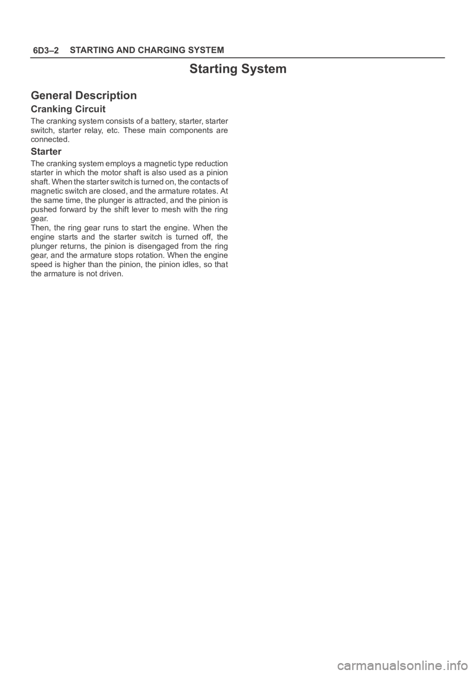
General Description
Cranking Circuit
The cranking system consists of a battery, starter, starter
switch, starter relay, etc. These main components are
connected.
Starter
The cranking system employs a magnetic type reduction
starter in which the motor shaft is also used as a pinion
shaft. When the starter switch is turned on, the contacts of
magnetic switch are closed, and the armature rotates. At
the same time, the plunger is attracted, and the pinion is
pushed forward by the shift lever to mesh with the ring
gear.
Then, the ring gear runs to start the engine. When the
engine starts and the starter switch is turned off, the
plunger returns, the pinion is disengaged from the ring
gear, and the armature stops rotation. When the engine
speed is higher than the pinion, the pinion idles, so that
the armature is not driven.
Page 1156 of 6000
6E–39 ENGINE DRIVEABILITY AND EMISSIONS
The data displayed on the other Tech 2 will appear the
same, with some exceptions. Some Tech 2s will only be
able to display certain vehicle parameters as values that
are a coded representation of the true or actual value. For
more information on this system of coding, refer to
Decimal/Binary/Hexadecimal Conversions. On this
vehicle Tech 2 displays the actual values for vehicle
parameters. It will not be necessary to perform any
conversions from coded values to actual values.
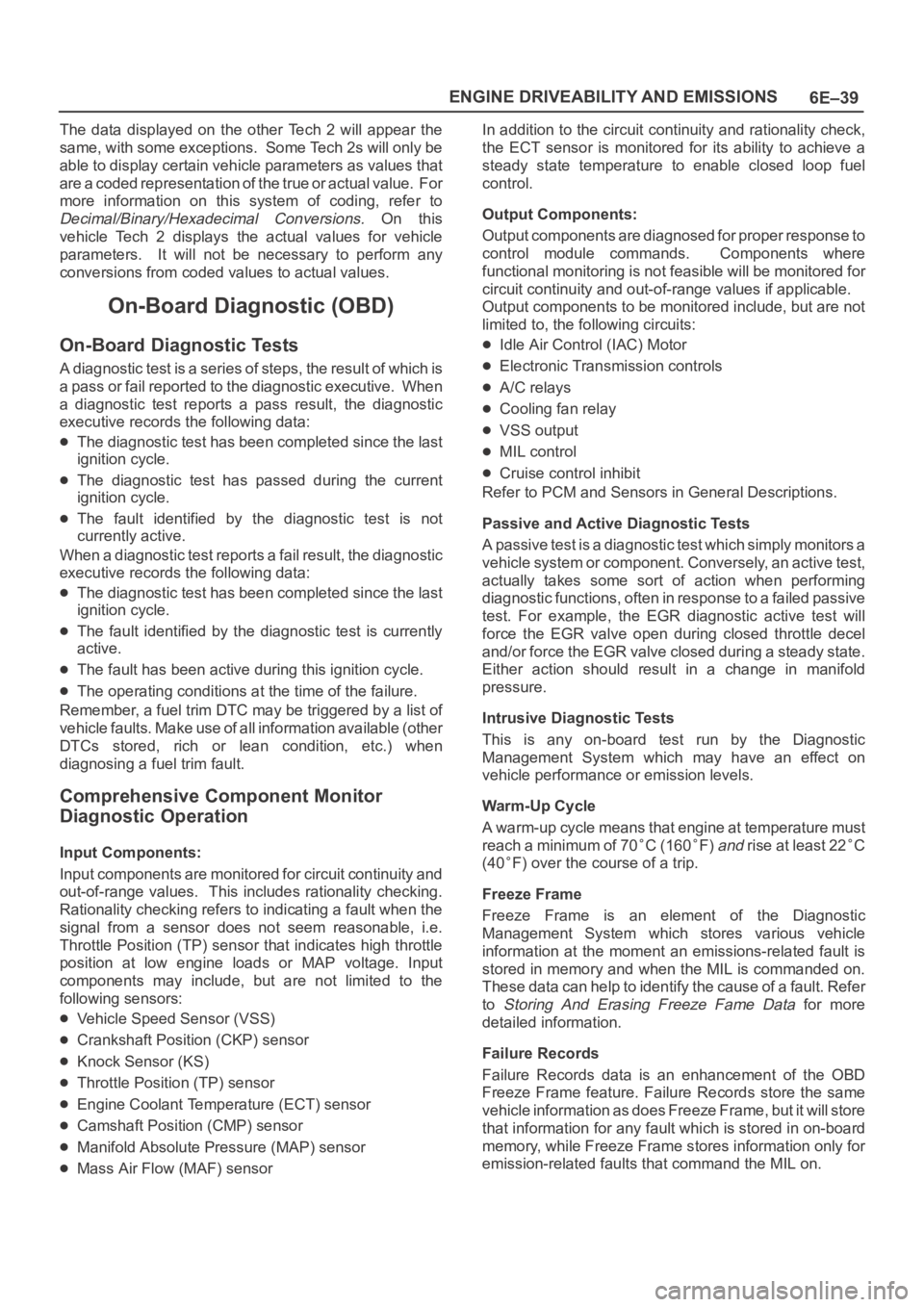
On-Board Diagnostic (OBD)
On-Board Diagnostic Tests
A diagnostic test is a series of steps, the result of which is
a pass or fail reported to the diagnostic executive. When
a diagnostic test reports a pass result, the diagnostic
executive records the following data:
The diagnostic test has been completed since the last
ignition cycle.
The diagnostic test has passed during the current
ignition cycle.
The fault identified by the diagnostic test is not
currently active.
W h e n a d i a g n o s t i c t e s t r e p o r t s a fail result, the diagnostic
executive records the following data:
The diagnostic test has been completed since the last
ignition cycle.
The fault identified by the diagnostic test is currently
active.
The fault has been active during this ignition cycle.
The operating conditions at the time of the failure.
Remember, a fuel trim DTC may be triggered by a list of
vehicle faults. Make use of all information available (other
DTCs stored, rich or lean condition, etc.) when
diagnosing a fuel trim fault.
Comprehensive Component Monitor
Diagnostic Operation
Input Components:
Input components are monitored for circuit continuity and
out-of-range values. This includes rationality checking.
Rationality checking refers to indicating a fault when the
signal from a sensor does not seem reasonable, i.e.
Throttle Position (TP) sensor that indicates high throttle
position at low engine loads or MAP voltage. Input
components may include, but are not limited to the
following sensors:
Vehicle Speed Sensor (VSS)
Crankshaft Position (CKP) sensor
Knock Sensor (KS)
Throttle Position (TP) sensor
Engine Coolant Temperature (ECT) sensor
Camshaft Position (CMP) sensor
Manifold Absolute Pressure (MAP) sensor
Mass Air Flow (MAF) sensorIn addition to the circuit continuity and rationality check,
the ECT sensor is monitored for its ability to achieve a
steady state temperature to enable closed loop fuel
control.
Output Components:
Output components are diagnosed for proper response to
control module commands. Components where
functional monitoring is not feasible will be monitored for
circuit continuity and out-of-range values if applicable.
Output components to be monitored include, but are not
limited to, the following circuits:
Idle Air Control (IAC) Motor
Electronic Transmission controls
A/C relays
Cooling fan relay
VSS output
MIL control
Cruise control inhibit
Refer to PCM and Sensors in General Descriptions.
Passive and Active Diagnostic Tests
A passive test is a diagnostic test which simply monitors a
vehicle system or component. Conversely, an active test,
actually takes some sort of action when performing
diagnostic functions, often in response to a failed passive
test. For example, the EGR diagnostic active test will
force the EGR valve open during closed throttle decel
and/or force the EGR valve closed during a steady state.
Either action should result in a change in manifold
pressure.
Intrusive Diagnostic Tests
This is any on-board test run by the Diagnostic
Management System which may have an effect on
vehicle performance or emission levels.
Warm-Up Cycle
A warm-up cycle means that engine at temperature must
reach a minimum of 70
C (160F) and rise at least 22C
(40
F) over the course of a trip.
Freeze Frame
Freeze Frame is an element of the Diagnostic
Management System which stores various vehicle
information at the moment an emissions-related fault is
stored in memory and when the MIL is commanded on.
These data can help to identify the cause of a fault. Refer
to
Storing And Erasing Freeze Fame Data for more
detailed information.
Failure Records
Failure Records data is an enhancement of the OBD
Freeze Frame feature. Failure Records store the same
vehicle information as does Freeze Frame, but it will store
that information for any fault which is stored in on-board
memory, while Freeze Frame stores information only for
emission-related faults that command the MIL on.