automatic transmission fluid OPEL FRONTERA 1998 Owner's Guide
[x] Cancel search | Manufacturer: OPEL, Model Year: 1998, Model line: FRONTERA, Model: OPEL FRONTERA 1998Pages: 6000, PDF Size: 97 MB
Page 2271 of 6000
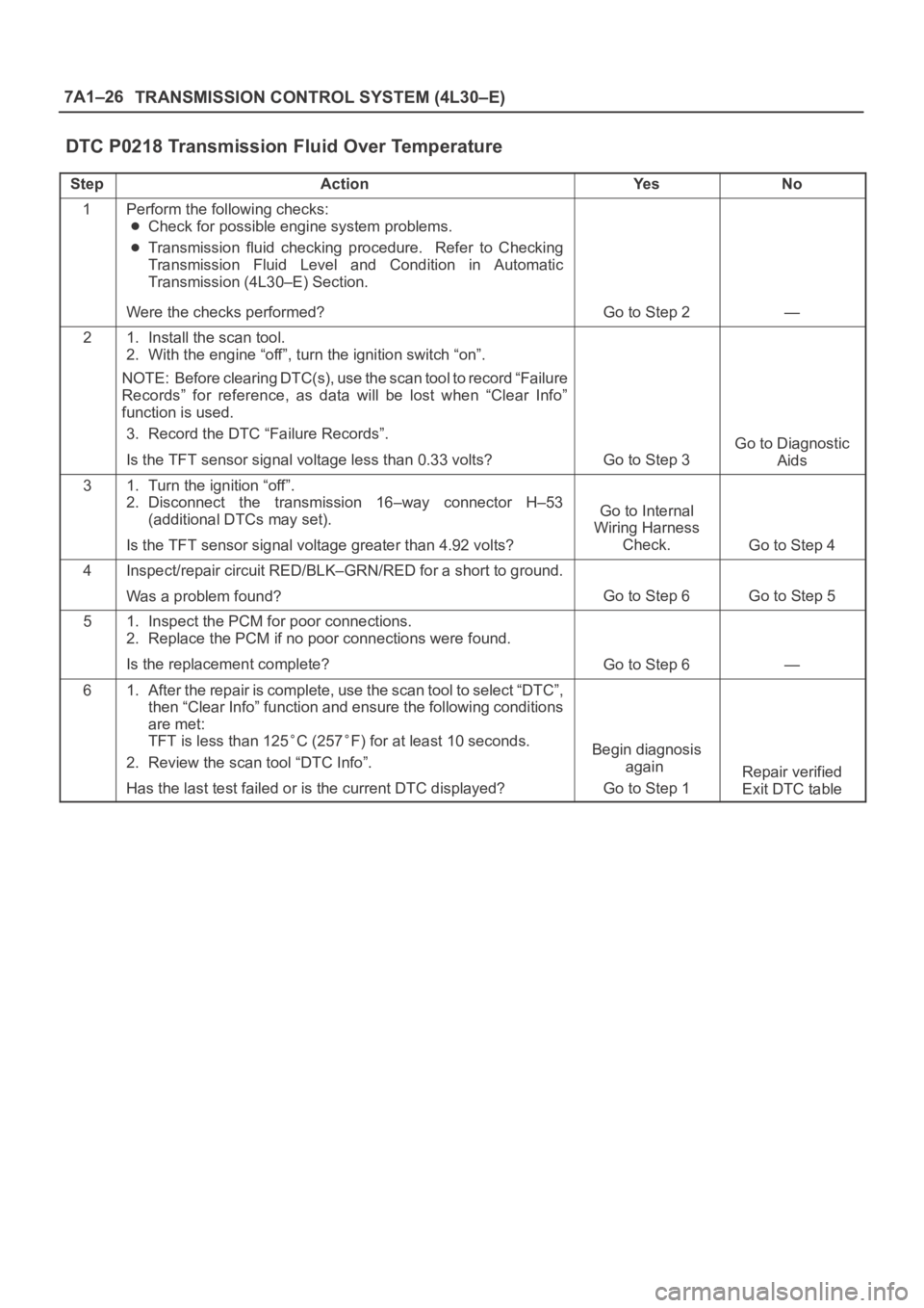
7A1–26
TRANSMISSION CONTROL SYSTEM (4L30–E)
DTC P0218 Transmission Fluid Over Temperature
StepActionYe sNo
1Perform the following checks:
Check for possible engine system problems.
Transmission fluid checking procedure. Refer to Checking
Transmission Fluid Level and Condition in Automatic
Transmission (4L30–E) Section.
Were the checks performed?
Go to Step 2—
21. Install the scan tool.
2. With the engine “off”, turn the ignition switch “on”.
NOTE: Before clearing DTC(s), use the scan tool to record “Failure
Records” for reference, as data will be lost when “Clear Info”
function is used.
3. Record the DTC “Failure Records”.
Is the TFT sensor signal voltage less than 0.33 volts?
Go to Step 3
Go to Diagnostic
Aids
31. Turn the ignition “off”.
2. Disconnect the transmission 16–way connector H–53
(additional DTCs may set).
Is the TFT sensor signal voltage greater than 4.92 volts?
Go to Internal
Wiring Harness
Check.
Go to Step 4
4Inspect/repair circuit RED/BLK–GRN/RED for a short to ground.
Was a problem found?
Go to Step 6Go to Step 5
51. Inspect the PCM for poor connections.
2. Replace the PCM if no poor connections were found.
Is the replacement complete?
Go to Step 6—
61. After the repair is complete, use the scan tool to select “DTC”,
then “Clear Info” function and ensure the following conditions
are met:
TFT is less than 125
C (257F) for at least 10 seconds.
2. Review the scan tool “DTC Info”.
Has the last test failed or is the current DTC displayed?Begin diagnosis
again
Go to Step 1
Repair verified
Exit DTC table
Page 2282 of 6000
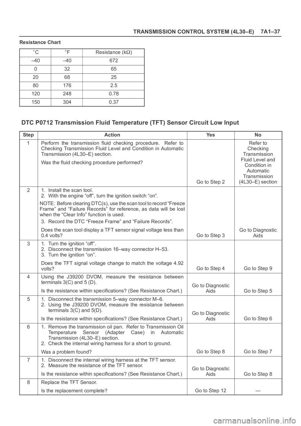
TRANSMISSION CONTROL SYSTEM (4L30–E)7A1–37
Resistance Chart
CFResistance (k)
–40–40672
03265
206825
801762.5
1202480.78
1503040.37
DTC P0712 Transmission Fluid Temperature (TFT) Sensor Circuit Low Input
StepActionYe sNo
1Perform the transmission fluid checking procedure. Refer to
Checking Transmission Fluid Level and Condition in Automatic
Transmission (4L30–E) section.
Was the fluid checking procedure performed?
Go to Step 2
Refer to
Checking
Transmission
Fluid Level and
Condition in
Automatic
Transmission
(4L30–E) section
21. Install the scan tool.
2. With the engine “off”, turn the ignition switch “on”.
NOTE: Before clearing DTC(s), use the scan tool to record “Freeze
Frame” and “Failure Records” for reference, as data will be lost
when the “Clear Info” function is used.
3. Record the DTC “Freeze Frame” and “Failure Records”.
Does the scan tool display a TFT sensor signal voltage less than
0.4 volts?
Go to Step 3
Go to Diagnostic
Aids
31. Turn the ignition “off”.
2. Disconnect the transmission 16–way connector H–53.
3. Turn the ignition “on”.
Does the TFT signal voltage change to match the voltage 4.92
volts?
Go to Step 4Go to Step 9
4Using the J39200 DVOM, measure the resistance between
terminals 3(C) and 5 (D).
Is the resistance within specifications? (See Resistance Chart.)
Go to Diagnostic
Aids
Go to Step 5
51. Disconnect the transmission 5–way connector M–6.
2. Using the J39200 DVOM, measure the resistance between
terminals 3(C) and 5(D).
Is the resistance within specifications? (See Resistance Chart.)
Go to Diagnostic
Aids
Go to Step 6
61. Remove the transmission oil pan. Refer to Transmission Oil
Temperature Sensor (Adapter Case) in Automatic
Transmission (4L30–E) section.
2. Check the internal wiring harness for a short to ground.
Was a problem found?
Go to Step 8Go to Step 7
71. Disconnect the internal wiring harness at the TFT sensor.
2. Measure the resistance of the TFT sensor.
Is the resistance within specifications? (See Resistance Chart.)
Go to Diagnostic
Aids
Go to Step 8
8Replace the TFT Sensor.
Is the replacement complete?
Go to Step 12—
Page 2283 of 6000

7A1–38
TRANSMISSION CONTROL SYSTEM (4L30–E)
DTC P0712 Transmission Fluid Temperature (TFT) Sensor Circuit Low Input (Cont’d)
StepNo Ye s Action
9Check circuit RED/BLK–GRN/RED for a short to ground.
Was a problem found?
Go to Step 12Go to Step 10
10Check the PCM for faulty connections.
Was a problem found?
Go to Step 12Go to Step 11
11Replace the PCM. Refer to Powertrain Control Module (PCM) in
Automatic Transmission (4L30–E) section.
Is the replacement complete?
Go to Step 12—
121. After the repair is complete, use the scan tool to select “DTC”,
then “Clear Info” function and ensure the following conditions
are met:
TFT sensor indicates a voltage greater than 0.33 volts for 2
seconds.
2. Review the scan tool “DTC info”.
Has the last test failed or is the current DTC displayed?
Begin diagnosis
again
Go to Step 1
Repair verified
Exit DTC table
Page 2285 of 6000
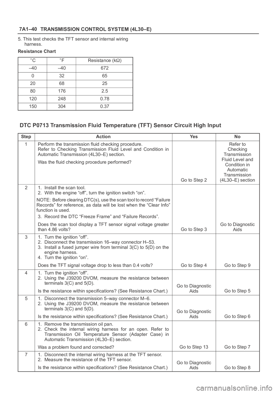
7A1–40
TRANSMISSION CONTROL SYSTEM (4L30–E)
5. This test checks the TFT sensor and internal wiring
harness.
Resistance Chart
CFResistance (k)
–40–40672
03265
206825
801762.5
1202480.78
1503040.37
DTC P0713 Transmission Fluid Temperature (TFT) Sensor Circuit High Input
StepActionYe sNo
1Perform the transmission fluid checking procedure.
Refer to Checking Transmission Fluid Level and Condition in
Automatic Transmission (4L30–E) section.
Was the fluid checking procedure performed?
Go to Step 2
Refer to
Checking
Transmission
Fluid Level and
Condition in
Automatic
Transmission
(4L30–E) section
21. Install the scan tool.
2. With the engine “off”, turn the ignition switch “on”.
NOTE: Before clearing DTC(s), use the scan tool to record “Failure
Records” for reference, as data will be lost when the “Clear Info”
function is used.
3. Record the DTC “Freeze Frame” and “Failure Records”.
Does the scan tool display a TFT sensor signal voltage greater
than 4.86 volts?
Go to Step 3
Go to Diagnostic
Aids
31. Turn the ignition “off”.
2. Disconnect the transmission 16–way connector H–53.
3. Install a fused jumper wire from terminal 3(C) to 5(D) on the
engine harness.
4. Turn the ignition “on”.
Does the TFT signal voltage drop to less than 0.4 volts?
Go to Step 4Go to Step 9
41. Turn the ignition “off”.
2. Using the J39200 DVOM, measure the resistance between
terminals 3(C) and 5(D).
Is the resistance within specifications? (See Resistance Chart.)
Go to Diagnostic
Aids
Go to Step 5
51. Disconnect the transmission 5–way connector M–6.
2. Using the J39200 DVOM, measure the resistance between
terminals 3(C) and 5(D).
Is the resistance within specifications? (See Resistance Chart.)
Go to Diagnostic
Aids
Go to Step 6
61. Remove the transmission oil pan.
2. Check the internal wiring harness for an open. Refer to
Transmission Oil Temperature Sensor (Adapter Case) in
Automatic Transmission (4L30–E) section.
Was a problem found and corrected?
Go to Step 13Go to Step 7
71. Disconnect the internal wiring harness at the TFT sensor.
2. Measure the resistance of the TFT sensor.
Is the resistance within specifications? (See Resistance Chart.)
Go to Diagnostic
Aids
Go to Step 8
Page 2286 of 6000

TRANSMISSION CONTROL SYSTEM (4L30–E)7A1–41
DTC P0713 Transmission Fluid Temperature (TFT) Sensor Circuit High Input (Cont’d)
StepNo Ye s Action
8Replace TFT sensor. Refer to Transmission Oil Temperature
Sensor (Adapter Case) in Automatic Transmission (4L30–E)
section.
Is the replacement complete?
Go to Step 13—
9Check circuit RED/BLK–GRN/RED for an open or short to B+.
Was a problem found?
Go to Step 13Go to Step 10
10Check circuit GRY–GRN for an open.
Was a problem found?
Go to Step 13Go to Step 11
11Check the PCM for faulty or intermittent connections.
Was a problem found?
Go to Step 13Go to Step 12
12Replace the PCM. Refer to Powertrain Control Module (PCM) in
Automatic Transmission (4L30–E) section.
Is the replacement complete?
Go to Step 13—
131. After the repair is complete, use the scan tool to select “DTC”,
then “Clear Info” function and ensure the following conditions
are met:
2. TFT sensor indicates a voltage less than 4.92 volts for 2
seconds.
3. Review the scan tool “DTC Info”.
Has the last test failed or is the current DTC displayed?
Begin diagnosis
again
Go to Step 1
Repair verified
Exit DTC table
Page 2297 of 6000

7A1–52
TRANSMISSION CONTROL SYSTEM (4L30–E)
Conditions For Clearing The DTC/CHECK
TRANS Lamp
The PCM will turn “off” the CHECK TRANS Lamp
after three consecutive ignition cycles without a
failure reported.
The DTC can be cleared from PCM memory by using
a scan tool.
The DTC can also be cleared from memory when the
vehicle has made 40 warmup cycles without a failure
reported.
The PCM will cancel the DTC Actions Taken items
when the fault conditions no longer exist and the
ignition is cycles “off” long enough to power down the
PCM.
Diagnostic Aids
Check for intermittent output speed sensor circuit
problems.
Check for possible incorrect calibration. (PCM part
No., tire specification, and rear axle ratio)
Test Description
The numbers below refer to the step numbers on the
diagnostic chart:
3. This step checks for possible low fluid level causing
slipping resulting in an undefined gear ratio.
4. This step checks for correct gear ratios for
commanded gears.
5. This step checks for low line pressure.
DTC P0730 Transmission Incorrect Gear Ratio
StepActionYe sNo
1Visually inspect the transmission cooling system for fluid leaks.
Refer to Chart 16: Possible Causes of Transmission Fluid
Leaks of Mechanical/Hydraulic Diagnosis Symptoms Index in
Automatic Transmission (4L30–E) section
Was condition found and corrected?
Go to Step 6Go to Step 2
2Refer to Checking Transmission Fluid Level and Condition in
Automatic Transmission (4L30–E) section.
Has transmission fluid checking procedure been performed?
Go to Step 3
Go to Checking
Transmission
Fluid Level and
Condition in
Automatic
Transmission
(4L30–E) section
31. Install the scan tool.
2. Turn the ignition switch to the “on” position.
3. Engine not running.
NOTE: Before clearing DTC(s) use the scan tool to record the
“Failure Records” for reference, as data will be lost when the “Clear
Info” function is used.
4. Record the Failure Record data.
5. Use the scan tool snapshot mode to record transmission gear
ratios.
6. Drive vehicle in transmission gear ranges 1, 2, 3, and D with
the engine speed is greater than 3,500 rpm for 5.5 seconds.
7. Record each transmission gear.
1st:2.73 – 2.99
2nd:1.54 – 1.71
3rd:0.93 – 1.05
4th:0.66 – 0.78
Does commanded gear ratio match ranges as shown?
Refer to
Diagnostic Aids
Go to Step 4
4Perform line pressure check.
Refer to Line Pressure Test in Automatic Transmission
(4L30–E) section.
Was condition found and corrected?
Go to Step 6Go to Step 5
Page 2311 of 6000
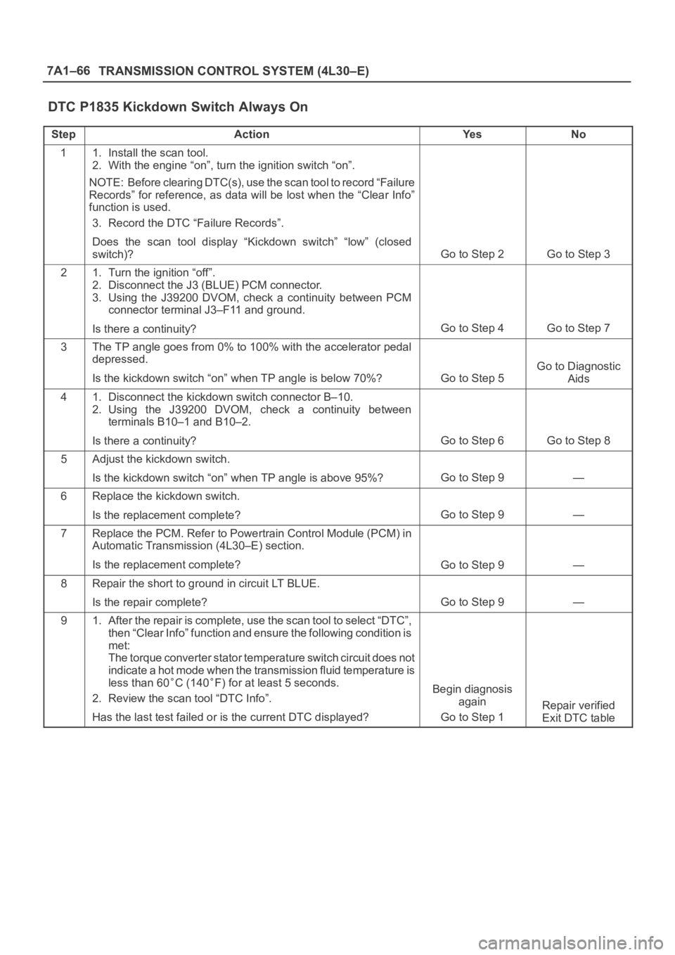
7A1–66
TRANSMISSION CONTROL SYSTEM (4L30–E)
DTC P1835 Kickdown Switch Always On
StepActionYe sNo
11. Install the scan tool.
2. With the engine “on”, turn the ignition switch “on”.
NOTE: Before clearing DTC(s), use the scan tool to record “Failure
Records” for reference, as data will be lost when the “Clear Info”
function is used.
3. Record the DTC “Failure Records”.
Does the scan tool display “Kickdown switch” “low” (closed
switch)?
Go to Step 2Go to Step 3
21. Turn the ignition “off”.
2. Disconnect the J3 (BLUE) PCM connector.
3. Using the J39200 DVOM, check a continuity between PCM
connector terminal J3–F11 and ground.
Is there a continuity?
Go to Step 4Go to Step 7
3The TP angle goes from 0% to 100% with the accelerator pedal
depressed.
Is the kickdown switch “on” when TP angle is below 70%?
Go to Step 5
Go to Diagnostic
Aids
41. Disconnect the kickdown switch connector B–10.
2. Using the J39200 DVOM, check a continuity between
terminals B10–1 and B10–2.
Is there a continuity?
Go to Step 6Go to Step 8
5Adjust the kickdown switch.
Is the kickdown switch “on” when TP angle is above 95%?
Go to Step 9—
6Replace the kickdown switch.
Is the replacement complete?
Go to Step 9—
7Replace the PCM. Refer to Powertrain Control Module (PCM) in
Automatic Transmission (4L30–E) section.
Is the replacement complete?
Go to Step 9—
8Repair the short to ground in circuit LT BLUE.
Is the repair complete?
Go to Step 9—
91. After the repair is complete, use the scan tool to select “DTC”,
then “Clear Info” function and ensure the following condition is
met:
The torque converter stator temperature switch circuit does not
indicate a hot mode when the transmission fluid temperature is
less than 60
C (140F) for at least 5 seconds.
2. Review the scan tool “DTC Info”.
Has the last test failed or is the current DTC displayed?Begin diagnosis
again
Go to Step 1
Repair verified
Exit DTC table
Page 4595 of 6000

6B–2
ENGINE COOLING
General Description
030RW001
Legend
(1) Water Pump
(2) Thermostat
(3) Radiator
(4) Reserve Tank
(5) Cooling Fan
(6) Cylinder Block(7) Cylinder Head
(8) Right Bank
(9) Throttle Body
(10) Cylinder Block
(11) Cylinder Head
(12) Left Bank
(13) Heater
The cooling system is a pressurized Engine Coolant (EC)
forced circulation type which consists of a water pump,
thermostat cooling fan, radiator and other components.
The automatic transmission fluid is cooled by the EC in
radiator.
Water Pump
The EC pump is a centrifugal impeller type and is driven
by a timing belt.
030RS001
Page 4599 of 6000
6B–6
ENGINE COOLING
Draining and Refilling Cooling
System
Before draining the cooling system, inspect the system
and perform any necessary service to ensure that it is
clean, does not leak and is in proper working order. The
engine coolant (EC) level should be between the “MIN”
and “MAX” lines of reserve tank when the engine is cold.
If low, check for leakage and add EC up to the “MAX” line.
There should not be any excessive deposit of rust or
scales around the radiator cap or radiator filler hole, and
the EC should also be free from oil.
Replace the EC if excessively dirty.
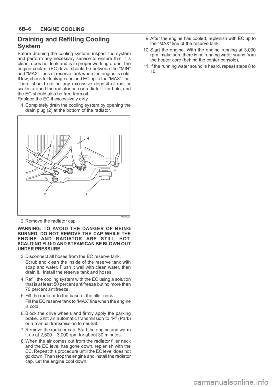
1. Completely drain the cooling system by opening the
drain plug (2) at the bottom of the radiator.
110RW002
2. Remove the radiator cap.
WARNING: TO AVOID THE DANGER OF BEING
BURNED, DO NOT REMOVE THE CAP WHILE THE
ENGINE AND RADIATOR ARE STILL HOT.
SCALDING FLUID AND STEAM CAN BE BLOWN OUT
UNDER PRESSURE.
3. Disconnect all hoses from the EC reserve tank.
Scrub and clean the inside of the reserve tank with
soap and water. Flush it well with clean water, then
drain it. Install the reserve tank and hoses.
4. Refill the cooling system with the EC using a solution
that is at least 50 percent antifreeze but no more than
70 percent antifreeze.
5. Fill the radiator to the base of the filler neck.
Fill the EC reserve tank to “MAX” line when the engine
is cold.
6. Block the drive wheels and firmly apply the parking
brake. Shift an automatic transmission to “P” (Park)
or a manual transmission to neutral.
7. Remove the radiator cap. Start the engine and warm
it up at 2,500
3,000 rpm for about 30 minutes.
8. When the air comes out from the radiator filler neck
and the EC level has gone down, replenish with the
EC. Repeat this procedure until the EC level does not
go down. Then stop the engine and install the radiator
cap. Let the engine cool down.9. After the engine has cooled, replenish with EC up to
the “MAX” line of the reserve tank.
10. Start the engine. With the engine running at 3,000
rpm, make sure there is no running water sound from
the heater core (behind the center console).
11. If the running water sound is heard, repeat steps 8 to
10.
Page 4622 of 6000

ENGINE ELECTRICAL6D1–3
a. VOLTAGE DOES NOT DROP BELOW THE
MINIMUM LISTED IN THE TABLE – The battery is
good and should be returned to service.
b. VOLTAGE IS LESS THAN MINIMUM LISTED –
Replace battery.
ESTIMATED TEMPERATURE
MINIMUM
VOLTAGE
FCV
70219.6
60169.5
50109.4
4049.3
30–19.1
20–78.9
10–128.7
0–188.5
The battery temperature must be estimated by feel
and by the temperature the battery has been
exposed to for the preceding few hours.
Battery Charging
Observe the following safety precautions when charging
the battery:
1. Never attempt to charge the battery when the fluid
level is below the lower level line on the side of the
battery. In this case, the battery must be replaced.
2. Pay close attention to the battery during charging
procedure.
Battery charging should be discontinued or the rate of
charge reduced if the battery feels hot to the touch.
Battery charging should be discontinued or the rate of
charge reduced if the battery begins to gas or spew
electrolyte from the vent holes.
3. In order to more easily view the hydrometer blue dot
or ring, it may be necessary to jiggle or tilt the battery.
4. Battery temperature can have a great effect on
battery charging capacity.
5. The sealed battery used on this vehicle may be either
quick charged or slow charged in the same manner as
other batteries.
Whichever method you decide to use, be sure that
you completely charge the battery. Never partially
charge the battery.
Jump Starting
Jump Starting with an Auxiliary (Booster)
Battery
CAUTION: Never push or tow the vehicle in an
attempt to start it. Serious damage to the emission
system as well as other vehicle parts will result.Treat both the discharged battery and the booster
battery with great care when using jumper cables.
Carefully follow the jump starting procedure, being
careful at all times to avoid sparking.
WARNING: FAILURE TO CAREFULLY FOLLOW THE
JUMP STARTING PROCEDURE COULD RESULT IN
THE FOLLOWING:
1. Serious personal injury, particularly to your eyes.
2. Property damage from a battery explosion, battery
acid, or an electrical fire.
3. Damage to the electronic components of one or both
vehicles particularly.
Never expose the battery to an open flame or electrical
spark. Gas generated by the battery may catch fire or
explode.
Remove any rings, watches, or other jewelry before
working around the battery. Protect your eyes by wearing
an approved set of goggles.
Never allow battery fluid to come in contact with your eyes
or skin.
Never allow battery fluid to come in contact with fabrics or
painted surfaces.
Battery fluid is a highly corrosive acid.
Should battery fluid come in contact with your eyes, skin,
fabric, or a painted surface, immediately and thoroughly
rinse the affected area with clean tap water.
Never allow metal tools or jumper cables to come in
contact with the positive battery terminal, or any other
metal surface of the vehicle. This will protect against a
short circuit.
Always keep batteries out of reach of young children.
Jump Starting Procedure
1. Set the vehicle parking brake.
If the vehicle is equipped with an automatic
transmission, place the selector level in the “PARK”
position.
If the vehicle is equipped with a manual transmission,
place the shift lever in the “NEUTRAL” position.
Turn “OFF” the ignition.
Turn “OFF” all lights and any other accessory
requiring electrical power.
2. Look at the built–in hydrometer.
If the indication area of the built–in hydrometer is
completely clear, do not try to jump start.
3. Attach the end of one jumper cable to the positive
terminal of the booster battery.
Attach the other end of the same cable to the positive
terminal of the discharged battery.
Do not allow the vehicles to touch each other. This will
cause a ground connection, effectively neutralizing
the charging procedure.
Be sure that the booster battery has a 12 volt rating.