warning OPEL FRONTERA 1998 Manual PDF
[x] Cancel search | Manufacturer: OPEL, Model Year: 1998, Model line: FRONTERA, Model: OPEL FRONTERA 1998Pages: 6000, PDF Size: 97 MB
Page 2568 of 6000
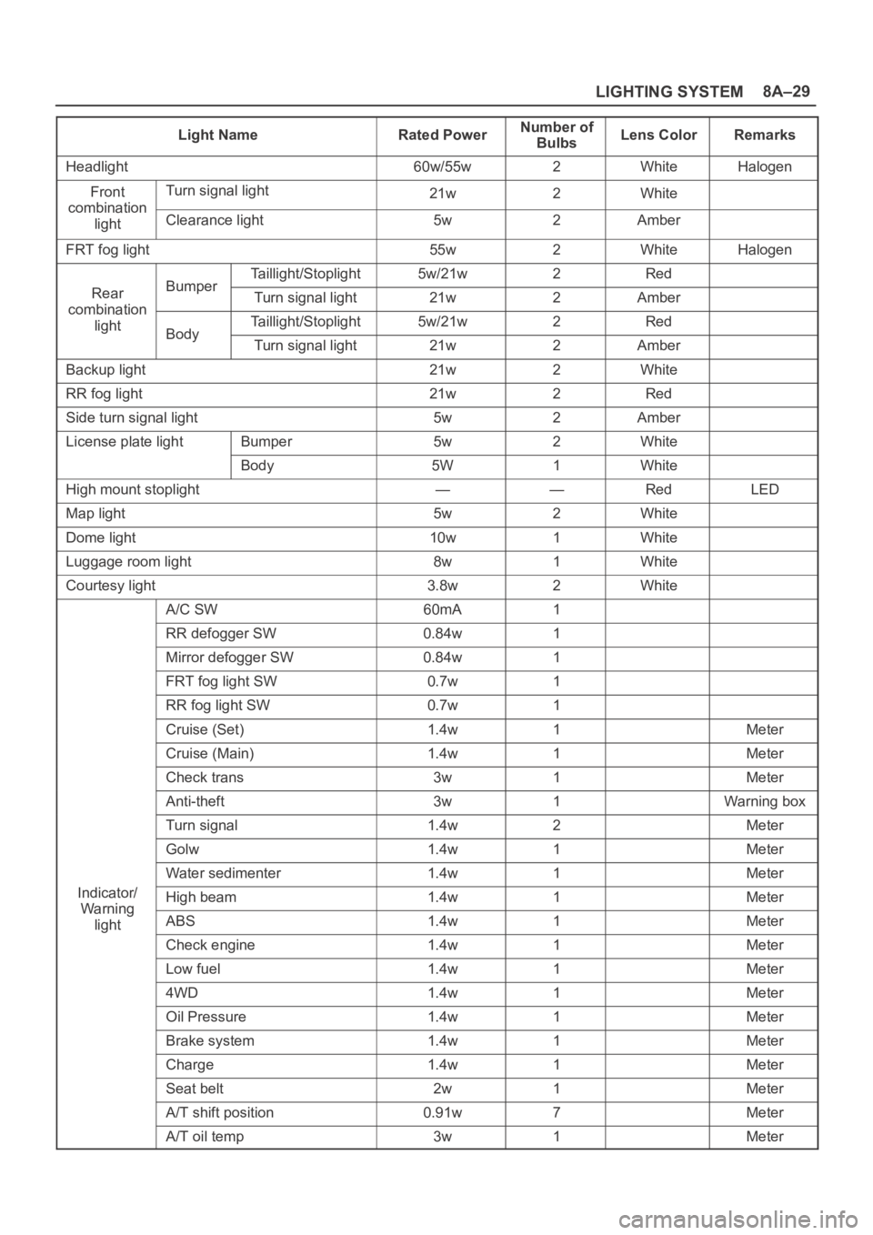
LIGHTING SYSTEM8A–29
Light NameRated PowerNumber of
BulbsLens ColorRemarks
Headlight60w/55w2WhiteHalogen
FrontTurn signal light21w2Whitecombination
lightClearance light5w2Amber
FRT fog light55w2WhiteHalogen
Taillight/Stoplight5w/21w2Red
RearBumperTurn signal light21w2Ambercombination
lightTaillight/Stoplight5w/21w2RedBodyTurn signal light21w2Amber
Backup light21w2White
RR fog light21w2Red
Side turn signal light5w2Amber
License plate lightBumper5w2White
Body5W1White
High mount stoplight——RedLED
Map light5w2White
Dome light10w1White
Luggage room light8w1White
Courtesy light3.8w2White
A/C SW60mA1
RR defogger SW0.84w1
Mirror defogger SW0.84w1
FRT fog light SW0.7w1
RR fog light SW0.7w1
Cruise (Set)1.4w1Meter
Cruise (Main)1.4w1Meter
Check trans3w1Meter
Anti-theft3w1Warning box
Turn signal1.4w2Meter
Golw1.4w1Meter
Water sedimenter1.4w1Meter
Indicator/High beam1.4w1MeterWa rnin g
lightABS1.4w1Meter
Check engine1.4w1Meter
Low fuel1.4w1Meter
4WD1.4w1Meter
Oil Pressure1.4w1Meter
Brake system1.4w1Meter
Charge1.4w1Meter
Seat belt2w1Meter
A/T shift position0.91w7Meter
A/T oil temp3w1Meter
Page 2569 of 6000
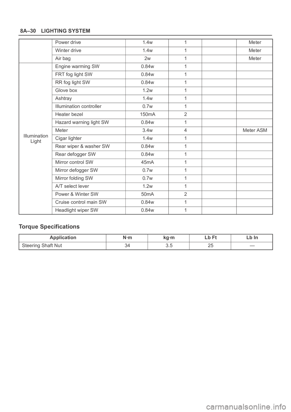
8A–30LIGHTING SYSTEM
Power drive1.4w1Meter
Winter drive1.4w1Meter
Air bag2w1Meter
Engine warming SW0.84w1
FRT fog light SW0.84w1
RR fog light SW0.84w1
Glove box1.2w1
Ashtray1.4w1
Illumination controller0.7w1
Heater bezel150mA2
Hazard warning light SW0.84w1
Meter3.4w4Meter ASM
IlluminationCigar lighter1.4w1Light
Rear wiper & washer SW0.84w1
Rear defogger SW0.84w1
Mirror control SW45mA1
Mirror defogger SW0.7w1
Mirror folding SW0.7w1
A/T select lever1.2w1
Power & Winter SW50mA2
Cruise control main SW0.84w1
Headlight wiper SW0.84w1
Torque Specifications
ApplicationNꞏmkgꞏmLb FtLb In
Steering Shaft Nut343.525—
Page 2571 of 6000
8B–2WIPER/WASHER SYSTEM
Service Precaution
WARNING: IF SO EQUIPPED WITH A
SUPPLEMENTAL RESTRAINT SYSTEM (SRS),
REFER TO THE SRS COMPONENT AND WIRING
LOCATION VIEW IN ORDER TO DETERMINE
WHETHER YOU ARE PERFORMING SERVICE ON OR
NEAR THE SRS COMPONENTS OR THE SRS
WIRING. WHEN YOU ARE PERFORMING SERVICE
ON OR NEAR THE SRS COMPONENTS OR THE SRS
WIRING, REFER TO THE SRS SERVICE
INFORMATION. FAILURE TO FOLLOW WARNINGS
COULD RESULT IN POSSIBLE AIR BAG
DEPLOYMENT, PERSONAL INJURY, OR
OTHERWISE UNNEEDED SRS SYSTEM REPAIRS.CAUTION: Always use the correct fastener in the
proper location. When you replace a fastener, use
ONLY the exact part number for that application.
ISUZU will call out those fasteners that require a
replacement after removal. ISUZU will also call out
the fasteners that require thread lockers or thread
sealant. UNLESS OTHERWISE SPECIFIED, do not
use supplemental coatings (Paints, greases, or other
corrosion inhibitors) on threaded fasteners or
fastener joint interfaces. Generally, such coatings
adversely affect the fastener torque and the joint
clamping force, and may damage the fastener. When
you install fasteners, use the correct tightening
sequence and specifications. Following these
instructions can help you avoid damage to parts and
systems.
Windshield Wiper/Washer System
General Description
The circuit consists of the starter switch, windshield wiper
& washer switch, windshield wiper motor, windshield
washer motor and windshield intermittent relay.When the wiper & washer switch is turned on with the
starter switch on, the battery voltage is applied to the
wiper motor to activate the wiper.
The washer motor squirts glass cleaning fluid while the
washer switch is being pushed. The intermittent relay is
used to control motion of the wiper.
Windshield Wiper And Washer Switch
Removal and Installation
Refer to the Lighting Switch (Combination Switch) in
Lighting System section.
Windshield Wiper Motor
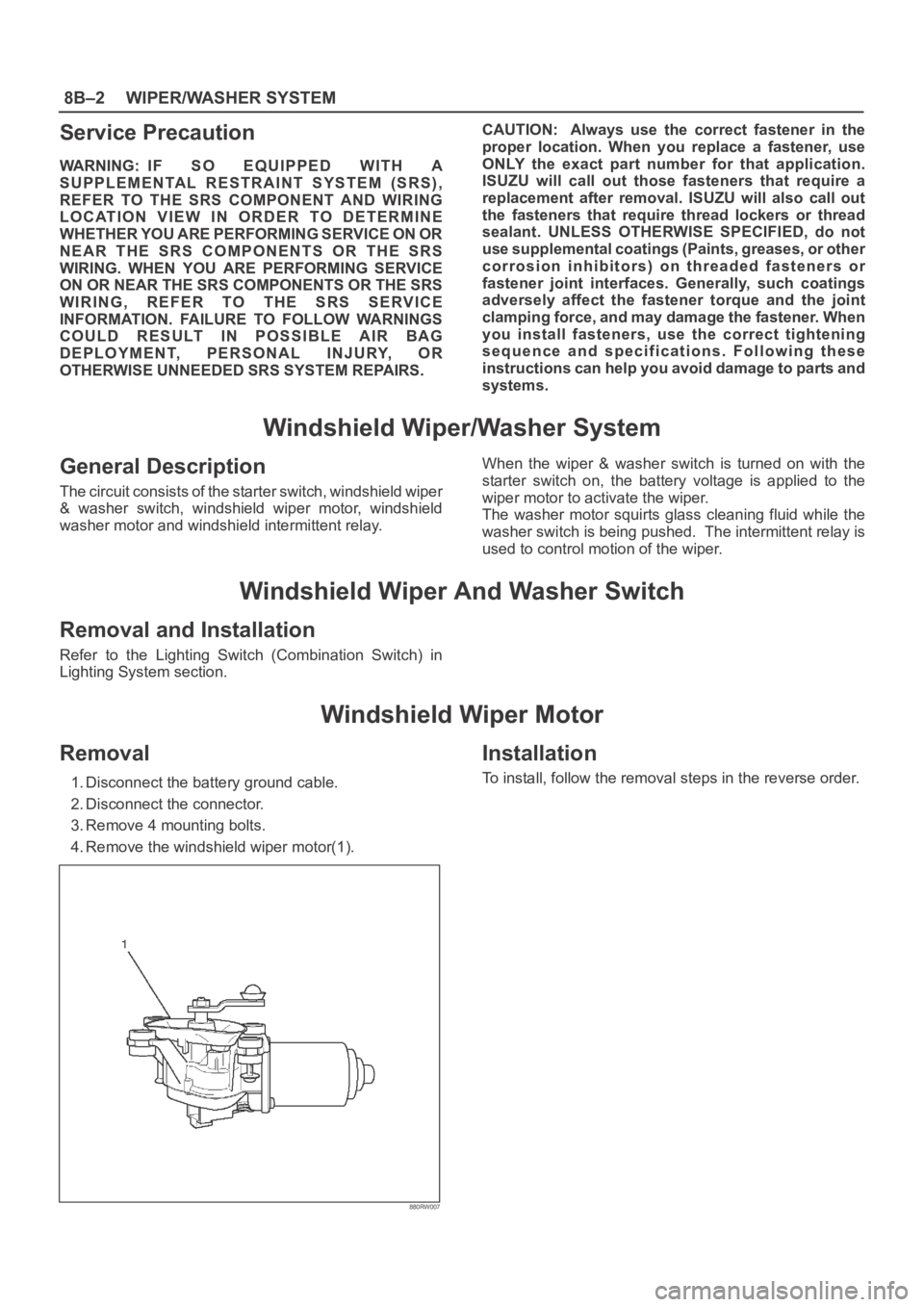
Removal
1. Disconnect the battery ground cable.
2. Disconnect the connector.
3. Remove 4 mounting bolts.
4. Remove the windshield wiper motor(1).
880RW007
Installation
To install, follow the removal steps in the reverse order.
Page 2584 of 6000
ENTERTAINMENT8C–1
BODY AND ACCESSORIES
ENTERTAINMENT
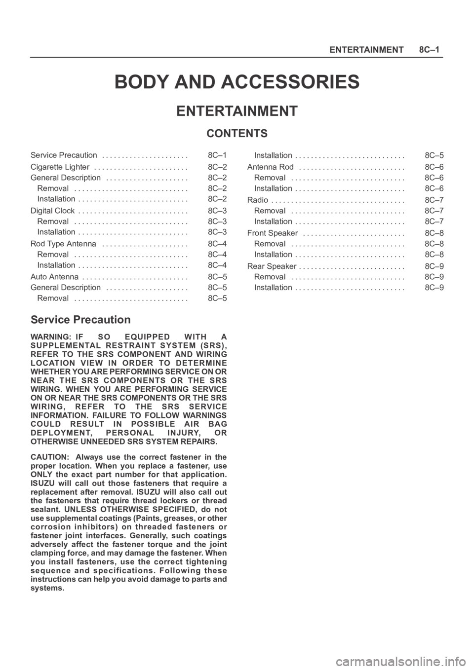
CONTENTS
Service Precaution 8C–1. . . . . . . . . . . . . . . . . . . . . .
Cigarette Lighter 8C–2. . . . . . . . . . . . . . . . . . . . . . . .
General Description 8C–2. . . . . . . . . . . . . . . . . . . . .
Removal 8C–2. . . . . . . . . . . . . . . . . . . . . . . . . . . . .
Installation 8C–2. . . . . . . . . . . . . . . . . . . . . . . . . . . .
Digital Clock 8C–3. . . . . . . . . . . . . . . . . . . . . . . . . . . .
Removal 8C–3. . . . . . . . . . . . . . . . . . . . . . . . . . . . .
Installation 8C–3. . . . . . . . . . . . . . . . . . . . . . . . . . . .
Rod Type Antenna 8C–4. . . . . . . . . . . . . . . . . . . . . .
Removal 8C–4. . . . . . . . . . . . . . . . . . . . . . . . . . . . .
Installation 8C–4. . . . . . . . . . . . . . . . . . . . . . . . . . . .
Auto Antenna 8C–5. . . . . . . . . . . . . . . . . . . . . . . . . . .
General Description 8C–5. . . . . . . . . . . . . . . . . . . . .
Removal 8C–5. . . . . . . . . . . . . . . . . . . . . . . . . . . . . Installation 8C–5. . . . . . . . . . . . . . . . . . . . . . . . . . . .
Antenna Rod 8C–6. . . . . . . . . . . . . . . . . . . . . . . . . . .
Removal 8C–6. . . . . . . . . . . . . . . . . . . . . . . . . . . . .
Installation 8C–6. . . . . . . . . . . . . . . . . . . . . . . . . . . .
Radio 8C–7. . . . . . . . . . . . . . . . . . . . . . . . . . . . . . . . . .
Removal 8C–7. . . . . . . . . . . . . . . . . . . . . . . . . . . . .
Installation 8C–7. . . . . . . . . . . . . . . . . . . . . . . . . . . .
Front Speaker 8C–8. . . . . . . . . . . . . . . . . . . . . . . . . .
Removal 8C–8. . . . . . . . . . . . . . . . . . . . . . . . . . . . .
Installation 8C–8. . . . . . . . . . . . . . . . . . . . . . . . . . . .
Rear Speaker 8C–9. . . . . . . . . . . . . . . . . . . . . . . . . . .
Removal 8C–9. . . . . . . . . . . . . . . . . . . . . . . . . . . . .
Installation 8C–9. . . . . . . . . . . . . . . . . . . . . . . . . . . .
Service Precaution
WARNING: IF SO EQUIPPED WITH A
SUPPLEMENTAL RESTRAINT SYSTEM (SRS),
REFER TO THE SRS COMPONENT AND WIRING
LOCATION VIEW IN ORDER TO DETERMINE
WHETHER YOU ARE PERFORMING SERVICE ON OR
NEAR THE SRS COMPONENTS OR THE SRS
WIRING. WHEN YOU ARE PERFORMING SERVICE
ON OR NEAR THE SRS COMPONENTS OR THE SRS
WIRING, REFER TO THE SRS SERVICE
INFORMATION. FAILURE TO FOLLOW WARNINGS
COULD RESULT IN POSSIBLE AIR BAG
DEPLOYMENT, PERSONAL INJURY, OR
OTHERWISE UNNEEDED SRS SYSTEM REPAIRS.
CAUTION: Always use the correct fastener in the
proper location. When you replace a fastener, use
ONLY the exact part number for that application.
ISUZU will call out those fasteners that require a
replacement after removal. ISUZU will also call out
the fasteners that require thread lockers or thread
sealant. UNLESS OTHERWISE SPECIFIED, do not
use supplemental coatings (Paints, greases, or other
corrosion inhibitors) on threaded fasteners or
fastener joint interfaces. Generally, such coatings
adversely affect the fastener torque and the joint
clamping force, and may damage the fastener. When
you install fasteners, use the correct tightening
sequence and specifications. Following these
instructions can help you avoid damage to parts and
systems.
Page 2650 of 6000
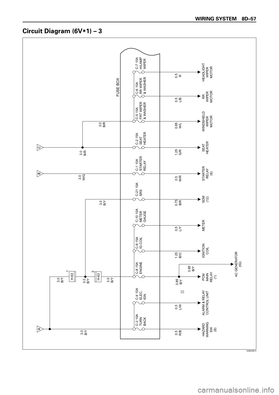
3.0
B/Y3.0
B/Y
3.0
B/Y3.0
B/Y3.0
W/G3.0
B/R
3.0
B/R 3.0
B/Y
0.5
R/B
HAZARD
WARNING
SW
(8)PCM
MAIN
RELAY
(1)IGNITION
COILMETER STARTER
RELAY
(6)SEAT
HEATERWINDSHIELD
WIPER
MOTORRR
WIPER
MOTORHEADLIGHT
WIPER
MOTOR
AC GENERATOR
(IG) ALARM & RELAY
CONTROL UNIT C-3 10A
TURN
BACK
0.5
L/WC-4 10A
ELEC.
IGN.
0.5
L/YC-10 10A
METER
GAUGE
0.5
W/RC-1 10A
STARTER
RELAY
0.85
W/LC-5 15A
FRT WIPER
& WASHERC-6 10A
RR WIPER
& WASHERC-7 10A
H/LAMP
WIPER
FUSE BOX
1.25
B/OC-9 15A
IG COIL C-8 15A
ENGINE
0.5
L/B
0.85
B/Y
0.85
B/Y
0.5
R
0.75
B/R
SDM
(12)C-21 10A
SRS
1.25
G/RC-2 15A
SEAT
HEATER
H-631
3
H-63
��
D08RWB15
Page 2658 of 6000

3.0
B/Y3.0
B/Y
3.0
B/Y3.0
B/Y3.0
W/G3.0
B/R
3.0
B/R 3.0
B/Y
0.5
R/B
HAZARD
WARNING
SW
(8)C-3 10A
TURN
BACK
0.5
L/WC-4 10A
ELEC.
IGN.
0.5
L/Y
METER ECM
(J2-9) ALARM & RELAY��
C O NTR O L UNITC-10 10A
METER
GAUGE
0.5
W/R
STARTER
RELAY
(6)C-1 10A
STARTER
RELAY
0.85
W/L
WINDSHIELD
WIPER
MOTORC-5 15A
FRT WIPER
& WASHERC-6 10A
RR WIPER
& WASHERC-7 10A
H/LAMP
WIPER
FUSE BOX
C-8 15A
ENGINE
0.5
L/B
RR
WIPER
MOTORHEADLIGHT
WIPER
MOTOR
0.85
B/Y
0.5
R
0.75
B/R
SDM
(12)C-21 10A
SRS
1.25
G/R
SEAT
HEATERC-2 15A
SEAT
HEATER
H-631
3
H-63
��
D08RWB20
Page 2661 of 6000

X-17M-25H-10H-12M-25 3.0
W/G
C-1 10A
STARTER RELAYFL-2 50A
KEY SWC-8 15A
ENGINE
MODE SW
(A/T)(M/T)
AC GENERATOR
STARTER
RELAY
STARTER SW
(ST)FL-1
PCM(C12)STARTER SW
(IG1)
STARTER SW(B2)
SHIFT LOCK
CONTROLLER(5)CHARGE
WARNING
LIGHT
(METER) FL-1
0.5
W/R
0.5
W/L
1.25
W/L
1.25
W/R
0.5
W/R0.5
W/R3.0
W/B
3.0
W/B
3.0
W/B
3.0
B/Y0.85
Y 0.5
W/R
0.85
W/G 0.85
W/G 0.85
W/G0.85
W/G0.75
W/G5.0
W 5.0
W
0.75
B/Y5.0
W 5.0
W
5.0
W
5.0
W 0.85
B/Y 0.85
B/Y3.0
B/Y
0.5
W/L
0.5
L2
15
1
4
32
10 11 423 3
2
1
1
10 1321 19 2
6
5 4
16
H-10H-42X-17
H-1X-17
H-13X-17
H-15P-8H-3
P-9
5.0
W
1
H-14
P-8H-3
X-17
H-16
H-3
H-2
H-2
H-15
H-14
P-8
A
B
C
D
X-17
IG
LB C
D08RW585
Page 2665 of 6000

3.0
B/Y STARTER SW
(IG1)
C-19 25A
BLOWER C-8 15A
ENGINEB-19
BODY-RH
FENDER-RH 0.85
W/G
0.3
B
1.25
B 0.85
W/G 0.5
B
0.85
W/G0.85
W/G0.85
W/G
HEATER & A/C
RELAY AC
GENERATOR
B-36B-36
BLOWER
MOTOR
1
34
3.0
L/R
3.0
LC-20 10A
AIR CON
A/C THERMO
RELAY(2)0.5
BR B-36101 23
4
H-13
1
C-39
1
H-142
B-36
CHARGE
RELAY
X-17X-17
X-1719
H-15
X-17 X-17
1 32
P-82H-3
1
H-3
2
H-2
3
5
H-3
12
H-42
13
H-15
10
H-16
QOS III CONTROL
UNIT(6)
or
QOS/EGR
CONTROL UNIT(18)A/T SHIFT
CONTROLLER
(5)CHARGE
WARNING
LIGHT
(METER)
P-8
IG S
LB P-8
1
H-2 5.0
W
5.0
W 2.0
W/B
3.0
W/B
0.85
B/Y
0.85
B/Y0.85
B/Y
0.85
W/G
0.85
W/L 0.85
B/Y5.0
W
5.0
W
5.0
W
5.0
W
3.0
W 0.5
B
0.5
BP-9
D08RW633
Page 2667 of 6000

X-17M-25H-10H-8M-25 3.0
W/G
C-1 10A
STARTER RELAYFL-2 50A
KEY SWC-8 15A
ENGINE
MODE SW
(A/T)(M/T)
AC GENERATOR
STARTER
RELAY
STARTER SW
(ST)FL-1
PCM(C12)STARTER SW
(IG1)
STARTER SW(B2)
SHIFT LOCK
CONTROLLER(5)CHARGE
WARNING
LIGHT
(METER) FL-1
0.5
W/R
0.5
W/L
1.25
W/L
1.25
W/R
0.5
W/R0.5
W/R3.0
W/B
3.0
W/B
3.0
W/B
3.0
B/Y 0.5
W/R
0.85
W/G 0.85
W/G0.85
W/G0.75
W/G5.0
W 5.0
W
0.75
B/Y5.0
W 5.0
W
5.0
W
5.0
W 0.85
B/Y 0.85
B/Y3.0
B/Y
0.5
W/L
0.5
L1
15
1
4
3
1 423 3
2
1
1
5 1121 32
6
5 4
16
H-10H-42X-17
H-1X-17
H-15P-8H-3
P-9
5.0
W
1
H-14
P-8H-3
H-16
H-3
H-2
H-2
H-13
H-14
P-8
A
B
C
X-17
IG
LB C
D08RW894
Page 2671 of 6000

X-17
5
4
P-8
1H-32
H-21
H-22
H-133
X-17
3
H-32
C-39
3
P-8
IG
3
P-8
S
P-9
B
3
X-17
2
X-17
E
E
HEATER & A/C
RELAY
B-36
BLOWER
MOTORA/C THERMO
RELAY(2)
B-36
1.25
B 0.3
B
1
3 B-36
FENDER-RH
B-19
BODY-LH
3.0
B/Y
0.85
B/Y
0.85
B/Y
0.85
W/G 0.5
B
0.5
B0.5
B
CHARGE
RELAYA/C
GENERATOR
0.85
W/G 0.85
B/Y0.85
B/Y2.0
W/B
3.0
W/B
0.85
W/G
0.85
W/L5.0
W
5.0
W5.0
W
5.0
W
5.0
W
3.0
W
3.0
L/R
3.0
L0.5
BR 5.0
W STARTER SW
(IG1)
C-8 15A
ENGINE
3.0
L/B
0.5
O/G
0.5
O/G STARTER SW
(IG1)
C-11 10A
AUDIO(ACC)
C-19 25A
BLOWERC-20 10A
AIR CON
1
H-3
X-17
CHARGE
WARNING
LIGHT
(METER)QOS III
CONTROL UNIT(6)
OR
QOS/EGR
CONTROL UNIT(18) 1
B
A
2
4 B-361
H-14
D08RW898