wiring OPEL FRONTERA 1998 Service Manual
[x] Cancel search | Manufacturer: OPEL, Model Year: 1998, Model line: FRONTERA, Model: OPEL FRONTERA 1998Pages: 6000, PDF Size: 97 MB
Page 1075 of 6000

6C–8
ENGINE FUEL
7. Disconnect two fuel tank wiring connectors(4) on
front right side of tank.
8. Disconnect evapo fuel hose(5).
9. Disconnect fuel feed tube and fuel return tube(6).
NOTE: Handling of the fuel tube, be sure to refer “Fuel
Tube/Quick–Connect Fittings” in this section.
10. Remove fuel tank fixing bolts on both sides and
remove fuel tank(7).
Installation
1. Install fuel tank(7).
Place a flange on right side of tank on the bracket.
Install a flange on left side on the bracket from the
bottom, and tighten bolts to the specified torque.
Torque: 36 Nꞏm (3.7 Kgꞏm/27 lb ft)
2. Connect fuel feed tube and fuel return tube(6).
3. Connect evapo fuel hose(5).
4. Connect fuel tank wiring connector(4).
5. Install undercover(3).
6. Connect fuel filler hose, air breather hose and evapo
hose(2).
7. Install fender liner(1).
Mount fender liner to the wheel well.
Fill the tank with fuel and tighten fuel filler cap.
Connect battery ground cable.
Fuel Tube / Quick – Connect Fittings
Precautions
Lighting of Fires Prohibited.
Keep flames away from your work area to prevent the
inflammable from catching fire.
Disconnect the battery negative cable to prevent
shorting during work.
When welding or conducting other heat-generating
work on other parts, be sure to provide pretreatment
to protect the piping system from thermal damage or
spattering.
Cautions During Work
Do not expose the assembly to battery electrolyte or do
not wipe the assembly with a cloth used to wipe off spilt
battery electorolyte.
The piping wet with battery electrolyte cannot be used.
Be careful not to give a bending or twisting force to the
piping during the work. If deformed, replace with a new
piping.
Removal
1. Open the fuel cap to relieve the fuel pressure in the
tank.
If the fuel quick-connect fittings are dusty, clean with
an air blower, etc. and then remove it.
141RW016As some pressure may remain in the piping, cover the
connector with a cloth, etc. to prevent the splashing
of fuel in the first disconnection of the piping.
Page 1078 of 6000
6C–11
ENGINE FUEL
Fuel Gauge Unit
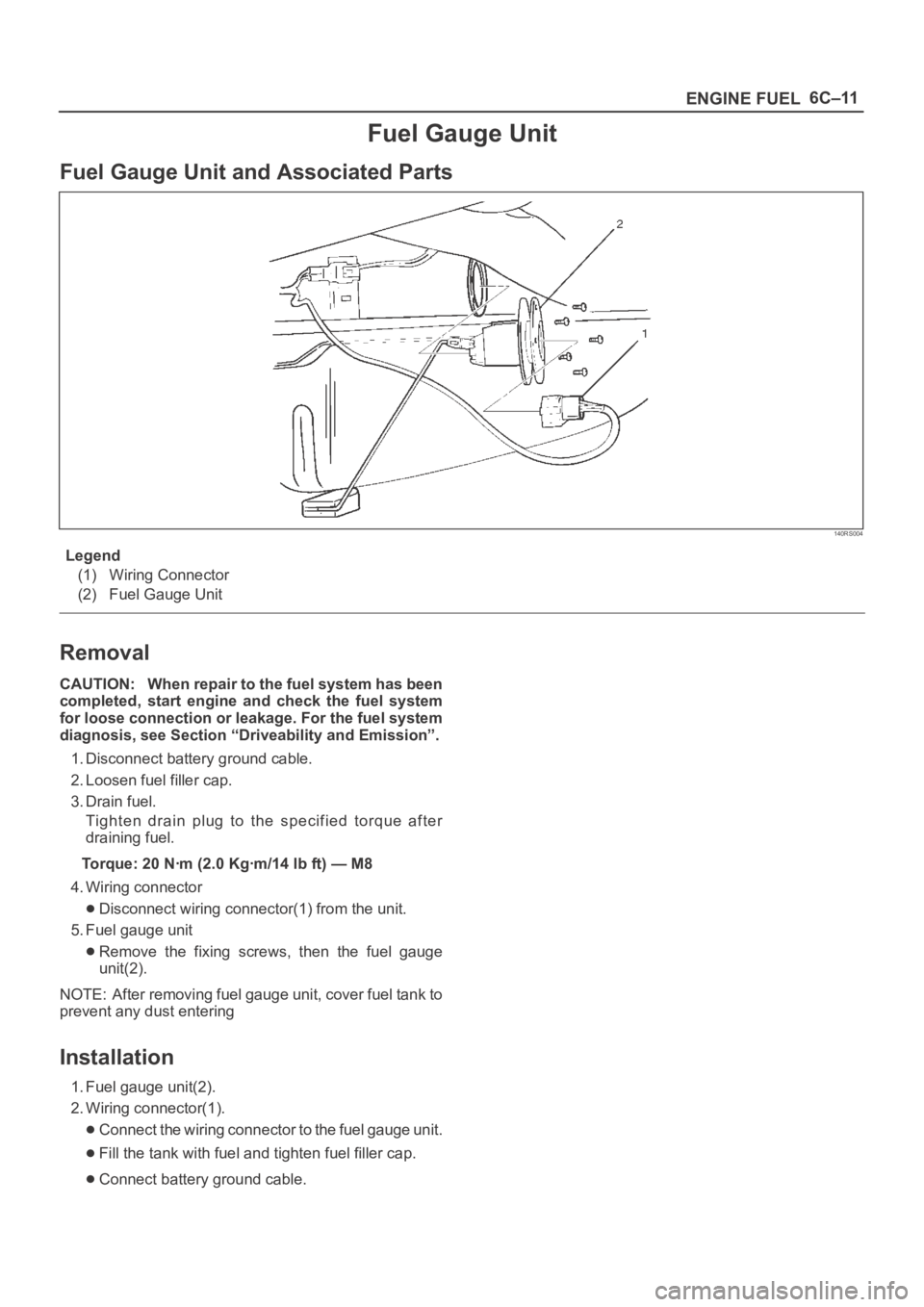
Fuel Gauge Unit and Associated Parts
140RS004
Legend
(1) Wiring Connector
(2) Fuel Gauge Unit
Removal
CAUTION: When repair to the fuel system has been
completed, start engine and check the fuel system
for loose connection or leakage. For the fuel system
diagnosis, see Section “Driveability and Emission”.
1. Disconnect battery ground cable.
2. Loosen fuel filler cap.
3. Drain fuel.
Tighten drain plug to the specified torque after
draining fuel.
Torque: 20 Nꞏm (2.0 Kgꞏm/14 lb ft) — M8
4. Wiring connector
Disconnect wiring connector(1) from the unit.
5. Fuel gauge unit
Remove the fixing screws, then the fuel gauge
unit(2).
NOTE: After removing fuel gauge unit, cover fuel tank to
prevent any dust entering
Installation
1. Fuel gauge unit(2).
2. Wiring connector(1).
Connect the wiring connector to the fuel gauge unit.
Fill the tank with fuel and tighten fuel filler cap.
Connect battery ground cable.
Page 1080 of 6000
ENGINE ELECTRICAL6D1–1
ENGINE
ENGINE ELECTRICAL
CONTENTS
Service Precaution 6D1–1. . . . . . . . . . . . . . . . . . . . . .
Battery 6D1–2. . . . . . . . . . . . . . . . . . . . . . . . . . . . . . . . .
General Description 6D1–2. . . . . . . . . . . . . . . . . . . .
Diagnosis 6D1–2. . . . . . . . . . . . . . . . . . . . . . . . . . . . .
Battery Charging 6D1–3. . . . . . . . . . . . . . . . . . . . . . Jump Starting 6D1–3. . . . . . . . . . . . . . . . . . . . . . . . .
Battery Removal 6D1–4. . . . . . . . . . . . . . . . . . . . . .
Battery Installation 6D1–4. . . . . . . . . . . . . . . . . . . . .
Main Data and Specifications 6D1–5. . . . . . . . . . .
Service Precaution
WARNING: IF SO EQUIPPED WITH A
SUPPLEMENTAL RESTRAINT SYSTEM (SRS),
REFER TO THE SRS COMPONENT AND WIRING
LOCATION VIEW IN ORDER TO DETERMINE
WHETHER YOU ARE PERFORMING SERVICE ON OR
NEAR THE SRS COMPONENTS OR THE SRS
WIRING. WHEN YOU ARE PERFORMING SERVICE
ON OR NEAR THE SRS COMPONENTS OR THE SRS
WIRING, REFER TO THE SRS SERVICE
INFORMATION. FAILURE TO FOLLOW WARNINGS
COULD RESULT IN POSSIBLE AIR BAG
DEPLOYMENT, PERSONAL INJURY, OR
OTHERWISE UNNEEDED SRS SYSTEM REPAIRS.
CAUTION: Always use the correct fastener in the
proper location. When you replace a fastener, use
ONLY the exact part number for that application.
ISUZU will call out those fasteners that require a
replacement after removal. ISUZU will also call out
the fasteners that require thread lockers or thread
sealant. UNLESS OTHERWISE SPECIFIED, do not
use supplemental coatings (Paints, greases, or other
corrosion inhibitors) on threaded fasteners or
fastener joint interfaces. Generally, such coatings
adversely affect the fastener torque and the joint
clamping force, and may damage the fastener. When
you install fasteners, use the correct tightening
sequence and specifications. Following these
instructions can help you avoid damage to parts and
systems.
Page 1086 of 6000
6D2–1
IGNITION SYSTEM
ENGINE
IGNITION SYSTEM
CONTENTS
Service Precaution 6D2–1. . . . . . . . . . . . . . . . . . . . . .
General Description 6D2–2. . . . . . . . . . . . . . . . . . . . .
Diagnosis 6D2–2. . . . . . . . . . . . . . . . . . . . . . . . . . . . . .
Ignition Coil 6D2–3. . . . . . . . . . . . . . . . . . . . . . . . . . . . .
Removal 6D2–3. . . . . . . . . . . . . . . . . . . . . . . . . . . . .
Inspection and Repair 6D2–3. . . . . . . . . . . . . . . . . .
Installation 6D2–3. . . . . . . . . . . . . . . . . . . . . . . . . . . .
Spark Plug 6D2–4. . . . . . . . . . . . . . . . . . . . . . . . . . . . . Removal 6D2–4. . . . . . . . . . . . . . . . . . . . . . . . . . . . .
Inspection and Repair 6D2–4. . . . . . . . . . . . . . . . . .
Installation 6D2–4. . . . . . . . . . . . . . . . . . . . . . . . . . . .
Crankshaft Angle Sensor 6D2–5. . . . . . . . . . . . . . . . .
Removal 6D2–5. . . . . . . . . . . . . . . . . . . . . . . . . . . . .
Installation 6D2–5. . . . . . . . . . . . . . . . . . . . . . . . . . . .
Main Data and Specifications 6D2–6. . . . . . . . . . . . .
Service Precaution
WARNING: IF SO EQUIPPED WITH A
SUPPLEMENTAL RESTRAINT SYSTEM (SRS),
REFER TO THE SRS COMPONENT AND WIRING
LOCATION VIEW IN ORDER TO DETERMINE
WHETHER YOU ARE PERFORMING SERVICE ON OR
NEAR THE SRS COMPONENTS OR THE SRS
WIRING. WHEN YOU ARE PERFORMING SERVICE
ON OR NEAR THE SRS COMPONENTS OR THE SRS
WIRING, REFER TO THE SRS SERVICE
INFORMATION. FAILURE TO FOLLOW WARNINGS
COULD RESULT IN POSSIBLE AIR BAG
DEPLOYMENT, PERSONAL INJURY, OR
OTHERWISE UNNEEDED SRS SYSTEM REPAIRS.
CAUTION: Always use the correct fastener in the
proper location. When you replace a fastener, use
ONLY the exact part number for that application.
ISUZU will call out those fasteners that require a
replacement after removal. ISUZU will also call out
the fasteners that require thread lockers or thread
sealant. UNLESS OTHERWISE SPECIFIED, do not
use supplemental coatings (Paints, greases, or other
corrosion inhibitors) on threaded fasteners or
fastener joint interfaces. Generally, such coatings
adversely affect the fastener torque and the joint
clamping force, and may damage the fastener. When
you install fasteners, use the correct tightening
sequence and specifications. Following these
instructions can help you avoid damage to parts and
systems.
Page 1090 of 6000
6D2–5
IGNITION SYSTEM
Crankshaft Angle Sensor
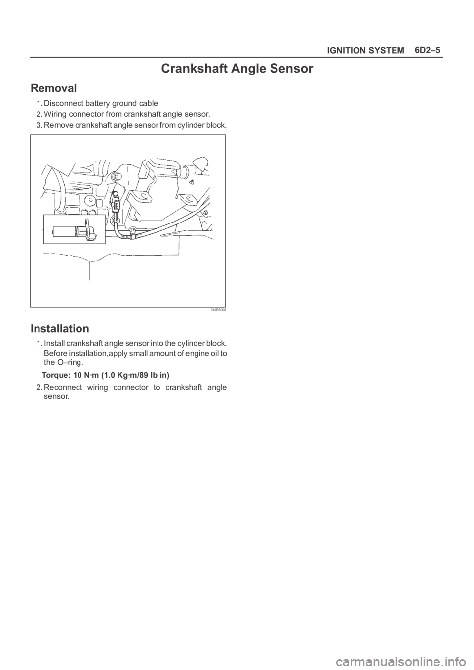
Removal
1. Disconnect battery ground cable
2. Wiring connector from crankshaft angle sensor.
3. Remove crankshaft angle sensor from cylinder block.
012RS008
Installation
1. Install crankshaft angle sensor into the cylinder block.
Before installation,apply small amount of engine oil to
the O–ring.
Torque: 10 Nꞏm (1.0 Kgꞏm/89 lb in)
2. Reconnect wiring connector to crankshaft angle
sensor.
Page 1092 of 6000
6D3–1 STARTING AND CHARGING SYSTEM
ENGINE
STARTING AND CHARGING SYSTEM
CONTENTS
Service Precaution 6D3–1. . . . . . . . . . . . . . . . . . . . . .
Starting System 6D3–2. . . . . . . . . . . . . . . . . . . . . . . . .
General Description 6D3–2. . . . . . . . . . . . . . . . . . . . .
Diagnosis 6D3–4. . . . . . . . . . . . . . . . . . . . . . . . . . . . . .
Starter 6D3–5. . . . . . . . . . . . . . . . . . . . . . . . . . . . . . . . .
Removal 6D3–5. . . . . . . . . . . . . . . . . . . . . . . . . . . . .
Installation 6D3–5. . . . . . . . . . . . . . . . . . . . . . . . . . . .
Disassembled View 6D3–6. . . . . . . . . . . . . . . . . . . .
Disassembly 6D3–7. . . . . . . . . . . . . . . . . . . . . . . . . .
Inspection and Repair 6D3–9. . . . . . . . . . . . . . . . . .
Reassembly 6D3–13. . . . . . . . . . . . . . . . . . . . . . . . . .
Main Data and Specifications 6D3–15. . . . . . . . . . .
Charging System 6D3–18. . . . . . . . . . . . . . . . . . . . . . . . General Description 6D3–18. . . . . . . . . . . . . . . . . . . . .
General On–Vehicle Inspection 6D3–18. . . . . . . . . . .
Generator 6D3–19. . . . . . . . . . . . . . . . . . . . . . . . . . . . . .
Removal 6D3–19. . . . . . . . . . . . . . . . . . . . . . . . . . . . .
Inspection 6D3–19. . . . . . . . . . . . . . . . . . . . . . . . . . . .
Installation 6D3–19. . . . . . . . . . . . . . . . . . . . . . . . . . . .
Disassembled View 6D3–20. . . . . . . . . . . . . . . . . . . .
Disassembly 6D3–21. . . . . . . . . . . . . . . . . . . . . . . . . .
Inspection and Repair 6D3–23. . . . . . . . . . . . . . . . . .
Reassembly 6D3–24. . . . . . . . . . . . . . . . . . . . . . . . . .
Bench Test 6D3–25. . . . . . . . . . . . . . . . . . . . . . . . . . .
Main Data and Specifications 6D3–26. . . . . . . . . . .
Service Precaution
WARNING: IF SO EQUIPPED WITH A
SUPPLEMENTAL RESTRAINT SYSTEM (SRS),
REFER TO THE SRS COMPONENT AND WIRING
LOCATION VIEW IN ORDER TO DETERMINE
WHETHER YOU ARE PERFORMING SERVICE ON OR
NEAR THE SRS COMPONENTS OR THE SRS
WIRING. WHEN YOU ARE PERFORMING SERVICE
ON OR NEAR THE SRS COMPONENTS OR THE SRS
WIRING, REFER TO THE SRS SERVICE
INFORMATION. FAILURE TO FOLLOW WARNINGS
COULD RESULT IN POSSIBLE AIR BAG
DEPLOYMENT, PERSONAL INJURY, OR
OTHERWISE UNNEEDED SRS SYSTEM REPAIRS.
CAUTION: Always use the correct fastener in the
proper location. When you replace a fastener, use
ONLY the exact part number for that application.
ISUZU will call out those fasteners that require a
replacement after removal. ISUZU will also call out
the fasteners that require thread lockers or thread
sealant. UNLESS OTHERWISE SPECIFIED, do not
use supplemental coatings (Paints, greases, or other
corrosion inhibitors) on threaded fasteners or
fastener joint interfaces. Generally, such coatings
adversely affect the fastener torque and the joint
clamping force, and may damage the fastener. When
you install fasteners, use the correct tightening
sequence and specifications. Following these
instructions can help you avoid damage to parts and
systems.
Page 1095 of 6000
6D3–4STARTING AND CHARGING SYSTEM
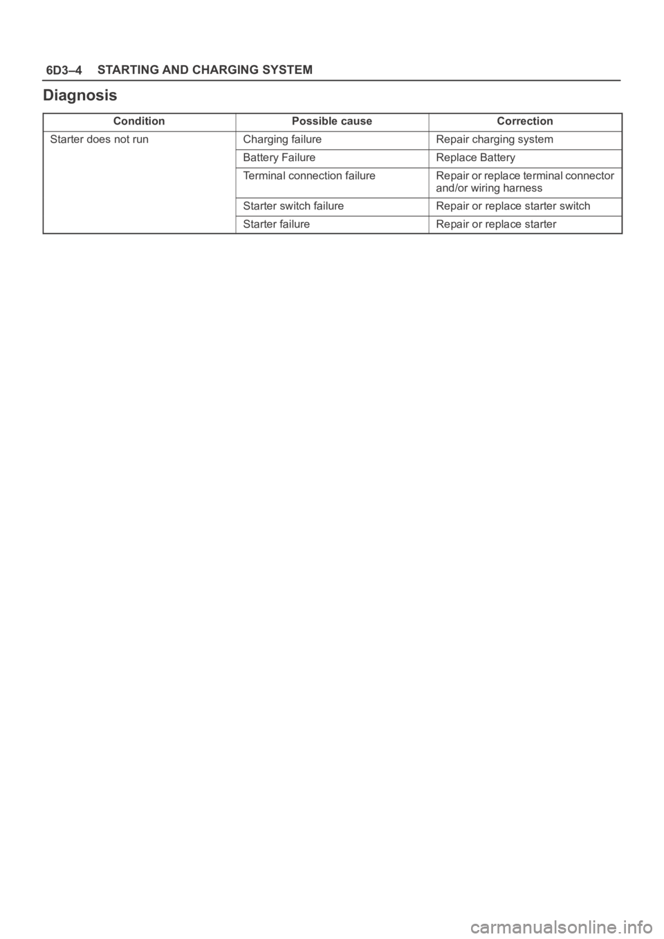
Diagnosis
ConditionPossible causeCorrection
Starter does not runCharging failureRepair charging system
Battery FailureReplace Battery
Terminal connection failureRepair or replace terminal connector
and/or wiring harness
Starter switch failureRepair or replace starter switch
Starter failureRepair or replace starter
Page 1096 of 6000
6D3–5 STARTING AND CHARGING SYSTEM
Starter
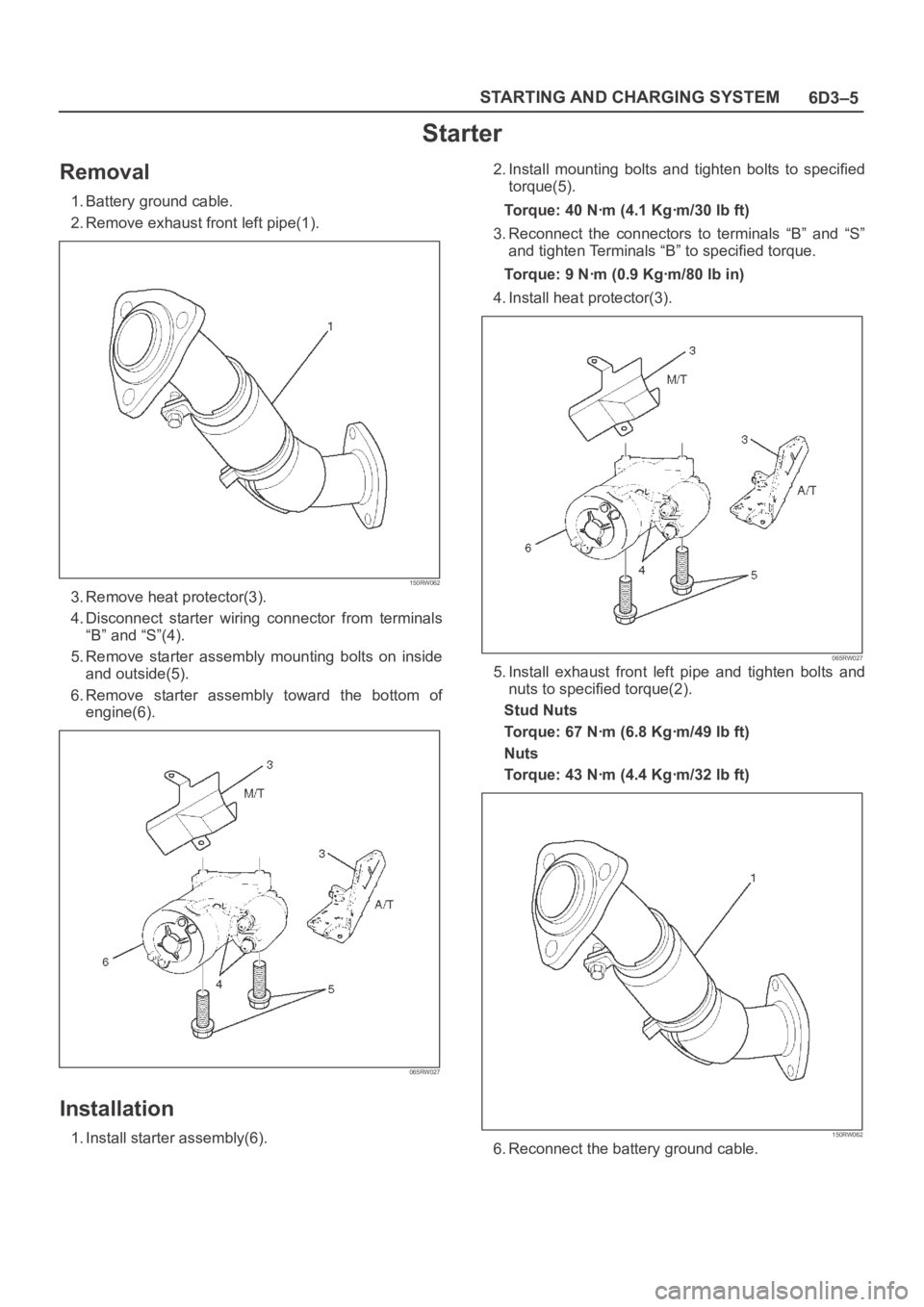
Removal
1. Battery ground cable.
2. Remove exhaust front left pipe(1).
150RW062
3. Remove heat protector(3).
4. Disconnect starter wiring connector from terminals
“B” and “S”(4).
5. Remove starter assembly mounting bolts on inside
and outside(5).
6. Remove starter assembly toward the bottom of
engine(6).
065RW027
Installation
1. Install starter assembly(6).2. Install mounting bolts and tighten bolts to specified
torque(5).
Torque: 40 Nꞏm (4.1 Kgꞏm/30 lb ft)
3. Reconnect the connectors to terminals “B” and “S”
and tighten Terminals “B” to specified torque.
Torque: 9 Nꞏm (0.9 Kgꞏm/80 lb in)
4. Install heat protector(3).
065RW027
5. Install exhaust front left pipe and tighten bolts and
nuts to specified torque(2).
Stud Nuts
Torque: 67 Nꞏm (6.8 Kgꞏm/49 lb ft)
Nuts
Torque: 43 Nꞏm (4.4 Kgꞏm/32 lb ft)
150RW062
6. Reconnect the battery ground cable.
Page 1109 of 6000
6D3–18STARTING AND CHARGING SYSTEM
Charging System
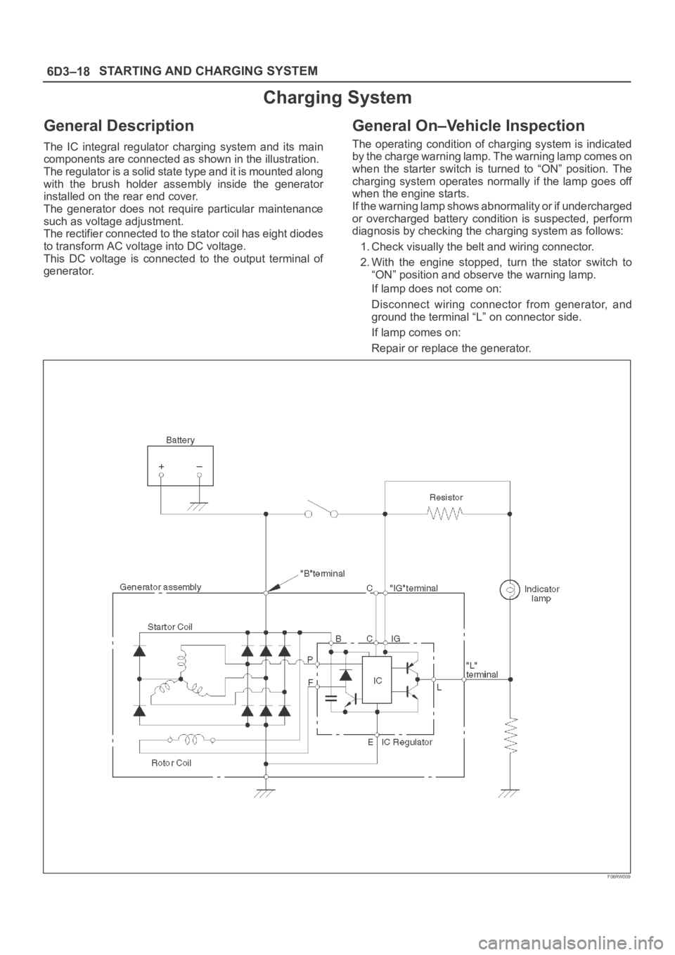
General Description
The IC integral regulator charging system and its main
components are connected as shown in the illustration.
The regulator is a solid state type and it is mounted along
with the brush holder assembly inside the generator
installed on the rear end cover.
The generator does not require particular maintenance
such as voltage adjustment.
The rectifier connected to the stator coil has eight diodes
to transform AC voltage into DC voltage.
This DC voltage is connected to the output terminal of
generator.
General On–Vehicle Inspection
The operating condition of charging system is indicated
by the charge warning lamp. The warning lamp comes on
when the starter switch is turned to “ON” position. The
charging system operates normally if the lamp goes off
when the engine starts.
If the warning lamp shows abnormality or if undercharged
or overcharged battery condition is suspected, perform
diagnosis by checking the charging system as follows:
1. Check visually the belt and wiring connector.
2. With the engine stopped, turn the stator switch to
“ON” position and observe the warning lamp.
If lamp does not come on:
Disconnect wiring connector from generator, and
ground the terminal “L” on connector side.
If lamp comes on:
Repair or replace the generator.
F06RW009
Page 1110 of 6000
6D3–19 STARTING AND CHARGING SYSTEM
Generator
Removal
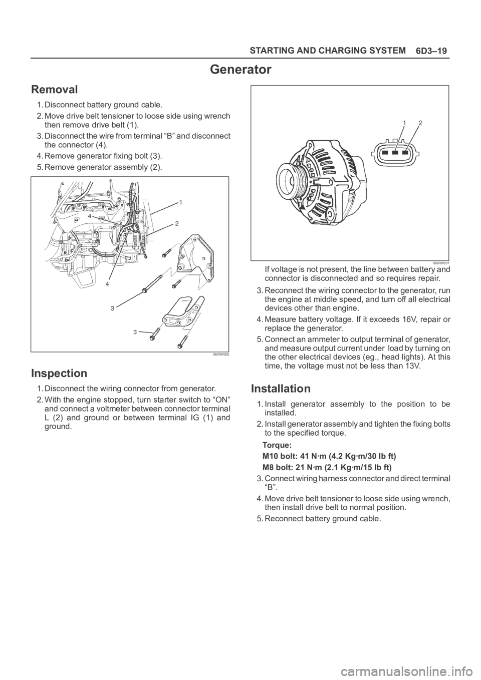
1. Disconnect battery ground cable.
2. Move drive belt tensioner to loose side using wrench
then remove drive belt (1).
3. Disconnect the wire from terminal “B” and disconnect
the connector (4).
4. Remove generator fixing bolt (3).
5. Remove generator assembly (2).
060RW002
Inspection
1. Disconnect the wiring connector from generator.
2. With the engine stopped, turn starter switch to “ON”
and connect a voltmeter between connector terminal
L (2) and ground or between terminal IG (1) and
ground.
066RW001If voltage is not present, the line between battery and
connector is disconnected and so requires repair.
3. Reconnect the wiring connector to the generator, run
the engine at middle speed, and turn off all electrical
devices other than engine.
4. Measure battery voltage. If it exceeds 16V, repair or
replace the generator.
5. Connect an ammeter to output terminal of generator,
and measure output current under load by turning on
the other electrical devices (eg., head lights). At this
time, the voltage must not be less than 13V.
Installation
1. Install generator assembly to the position to be
installed.
2. Install generator assembly and tighten the fixing bolts
to the specified torque.
To r q u e :
M10 bolt: 41 Nꞏm (4.2 Kgꞏm/30 lb ft)
M8 bolt: 21 Nꞏm (2.1 Kgꞏm/15 lb ft)
3. Connect wiring harness connector and direct terminal
“B”.
4. Move drive belt tensioner to loose side using wrench,
then install drive belt to normal position.
5. Reconnect battery ground cable.