OPEL FRONTERA 1998 Workshop Manual
FRONTERA 1998
OPEL
OPEL
https://www.carmanualsonline.info/img/37/57409/w960_57409-0.png
OPEL FRONTERA 1998 Workshop Manual
Trending: battery capacity, window, bolt pattern, washer fluid, roof, oil capacity, cooling
Page 781 of 6000
4D2–14
TRANSFER CASE (TOD)
6. Using the bearing remover 5-8840-2409-0 (J-42805)
and slide hammer 5-8840-0084-0 (J-2619-01),
remove the ball bearing for the front output shaft.
901RW234
7. Remove the bolts and front and rear speed sensors.
NOTE: Be careful not to damage the speed sensors
during the work.
261RW033
Reassembly
1. Remove the oil seal from the transfer cover assembly.
2. Apply oil to the circumference of the new oil seal and
fill the lip with grease (Besco L2 or equivalent).
3. Using the oil seal installer 5-8840-2412-0 (J-42804),
install the oil seal to the transfer cover assembly.
261RW051
Rear Output Shaft Oil Seal
Distance between the transfer case end and oil seal.
NOTE: When installing the oil seal to the specified
dimension, be careful not to damage it.
Dimension : 9.85 — 10.35mm (0.39 — 0.41 in)
A04RW004
Page 782 of 6000
4D2–15 TRANSFER CASE (TOD)
4. Apply a thin coat of grease to the seal ring of each
front and rear speed sensor, and mount the sensors
carefully.
5. Tighten the bolts to the specified torque.
Torque : 5 Nꞏm (0.5 kgꞏm/43 lb in)
NOTE: Pay attention not to mount the front (or rear)
sensor to the rear (or front) sensor position.
6. Install the ball bearing (1) for the front output shaft as
flat as shown in the figure.
261RW008
7. Mount the coil assembly and tighten the nuts to the
specified torque.
Torque : 10 Nꞏm (1.0 kgꞏm/87 lb in)
8. Connect the terminal in the central connector.
NOTE: Be careful not to damage other terminals.
9. Install speed gear and tone wheel.
10. Mount the ball bearing (2) as flat as shown in the
figure.
261RW009–1
11. Using snap ring pliers, install the snap ring to the
transfer cover assembly.NOTE: Securely install the snap ring to the groove of the
transfer cover assembly.
Page 783 of 6000
4D2–16
TRANSFER CASE (TOD)
Transfer Case Assembly Clutch Pack and Clutch Cam
Disassembled View
266RW006
Legend
(1) Clutch Pack Assembly
(2) Insulator Washer
(3) Armature Plate
(4) Snap Ring(5) Wave Spring
(6) Cam Pulley
(7) Cam Ball
(8) Cam and Coil Housing
(9) Thrust Bearing
Disassembly
1. Remove the thrust bearing.
2. Remove the cam and coil housing.
NOTE: When the cam and coil housing is removed, the
cam balls may be detached together with the housing. Be
careful not to lose the ball.
3. Remove the cam ball.
266RW013
Page 784 of 6000
4D2–17 TRANSFER CASE (TOD)
4. Remove the cam pulley.
5. Remove the wave spring.
6. Using snap ring pliers, remove the snap ring.
NOTE: Be careful not to damage the snap ring.
266RW009
7. Remove the armature plate.
8. Remove the insulator washer.
9. Remove the clutch pack assembly as a package.
266RW017
Page 785 of 6000
4D2–18
TRANSFER CASE (TOD)
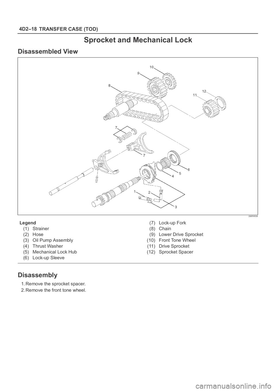
Sprocket and Mechanical Lock
Disassembled View
266RW008
Legend
(1) Strainer
(2) Hose
(3) Oil Pump Assembly
(4) Thrust Washer
(5) Mechanical Lock Hub
(6) Lock-up Sleeve(7) Lock-up Fork
(8) Chain
(9) Lower Drive Sprocket
(10) Front Tone Wheel
(11) Drive Sprocket
(12) Sprocket Spacer
Disassembly
1. Remove the sprocket spacer.
2. Remove the front tone wheel.
Page 786 of 6000
4D2–19 TRANSFER CASE (TOD)
3. Remove the drive sprocket, lower drive sprocket, and
chain together from the front and rear output shafts.
266RW010
4. Remove the mechanical lock hub.
5. Remove the lock-up fork.
6. Remove the spring retainer from the connection
between rail shaft and lock-up fork.
7. Remove the lock-up sleeve.
261RW018
8. Remove the thrust washer.
9. Remove the magnet from the strainer set position
together with the oil pump assembly.
10. Remove the strainer from the oil pump assembly.
11. Remove the hose from the oil pump assembly.
Page 787 of 6000
4D2–20
TRANSFER CASE (TOD)
Output Shafts and Shift Control Shaft
Disassembled View
261RW010–1
Legend
(1) Transfer Case Assembly
(2) Detent Spring
(3) Front Output Shaft
(4) Reduction Hub
(5) Output Shaft
(6) Reduction Fork Assembly
(7) Lock-up Shaft
(8) Spring Pin
(9) Reduction Fork(10) Cam Assembly
(11) Snap Ring
(12) Washer
(13) Cam
(14) Cam Pilot Block
(15) Shifter Shaft Assembly
(16) Shifter Lever Shaft
(17) Snap Ring
(18) Reduction Lever Assembly
(19) Snap Ring
Page 788 of 6000
4D2–21 TRANSFER CASE (TOD)
Disassembly
1. Remove the output shaft.
266RW011
2. Remove the detent spring.
3. Remove the cam pilot block bolts.
4. Remove the shifter shaft assembly and cam
assembly.
261RW019
5. Remove the spring pin that fixes the reduction fork to
the lock-up shaft.
261RW020
6. Remove the reduction fork.
7. Remove the lock-up shaft.
8. Using snap ring pliers, remove the snap ring from cam
pilot block.
261RW029
9. Remove the washer.
10. Remove the cam.
11. Remove the cam pilot block.
Page 789 of 6000
4D2–22
TRANSFER CASE (TOD)
12. Using snap ring pliers, remove the snap ring from
shifter lever shaft.
261RW021
13. Remove the reduction lever assembly.
14. Remove the snap ring.
15. Remove the shifter lever shaft.
16. Remove the front output shaft.
266RW012
17. Remove the transfer case assembly.
Page 790 of 6000
4D2–23 TRANSFER CASE (TOD)
Transfer Case
Disassembled View
265RW015
Legend
(1) Transfer Case
(2) Ball Bearing
(3) Ring Gear
(4) Snap Ring
(5) Input Shaft and Carrier Assembly
(6) Snap Ring(7) Ball Bearing
(8) Snap Ring
(9) Thrust Plate
(10) Carrier Assembly
(11) Snap Ring
(12) Circular Hub
(13) Input Shaft
Trending: lights, traction control, spare tire location, Front differential, wiring, fuel pump, MPG


