battery OPEL FRONTERA 1998 Manual Online
[x] Cancel search | Manufacturer: OPEL, Model Year: 1998, Model line: FRONTERA, Model: OPEL FRONTERA 1998Pages: 6000, PDF Size: 97 MB
Page 1182 of 6000
6E–65 ENGINE DRIVEABILITY AND EMISSIONS
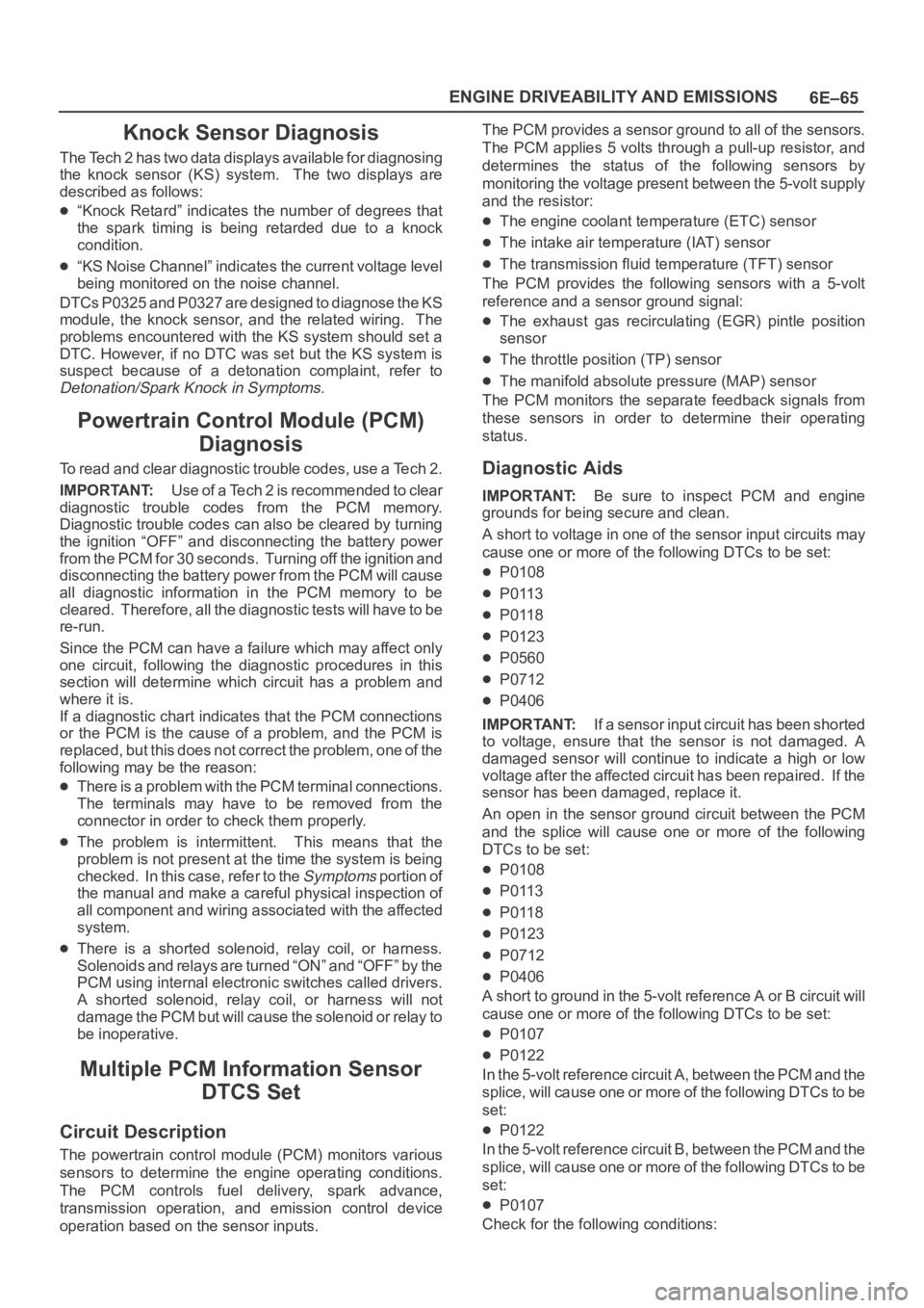
Knock Sensor Diagnosis
The Tech 2 has two data displays available for diagnosing
the knock sensor (KS) system. The two displays are
described as follows:
“Knock Retard” indicates the number of degrees that
the spark timing is being retarded due to a knock
condition.
“KS Noise Channel” indicates the current voltage level
being monitored on the noise channel.
DTCs P0325 and P0327 are designed to diagnose the KS
module, the knock sensor, and the related wiring. The
problems encountered with the KS system should set a
DTC. However, if no DTC was set but the KS system is
suspect because of a detonation complaint, refer to
Detonation/Spark Knock in Symptoms.
Powertrain Control Module (PCM)
Diagnosis
To read and clear diagnostic trouble codes, use a Tech 2.
IMPORTANT:Use of a Tech 2 is recommended to clear
diagnostic trouble codes from the PCM memory.
Diagnostic trouble codes can also be cleared by turning
the ignition “OFF” and disconnecting the battery power
from the PCM for 30 seconds. Turning off the ignition and
disconnecting the battery power from the PCM will cause
all diagnostic information in the PCM memory to be
cleared. Therefore, all the diagnostic tests will have to be
re-run.
Since the PCM can have a failure which may affect only
one circuit, following the diagnostic procedures in this
section will determine which circuit has a problem and
where it is.
If a diagnostic chart indicates that the PCM connections
or the PCM is the cause of a problem, and the PCM is
replaced, but this does not correct the problem, one of the
following may be the reason:
There is a problem with the PCM terminal connections.
The terminals may have to be removed from the
connector in order to check them properly.
The problem is intermittent. This means that the
problem is not present at the time the system is being
checked. In this case, refer to the
Symptoms p o r t i o n o f
the manual and make a careful physical inspection of
all component and wiring associated with the affected
system.
There is a shorted solenoid, relay coil, or harness.
S o l e n o i d s a n d r e l a y s a r e t u r n e d “ O N ” a n d “ O F F ” b y t h e
PCM using internal electronic switches called drivers.
A shorted solenoid, relay coil, or harness will not
damage the PCM but will cause the solenoid or relay to
be inoperative.
Multiple PCM Information Sensor
DTCS Set
Circuit Description
The powertrain control module (PCM) monitors various
sensors to determine the engine operating conditions.
The PCM controls fuel delivery, spark advance,
transmission operation, and emission control device
operation based on the sensor inputs.The PCM provides a sensor ground to all of the sensors.
The PCM applies 5 volts through a pull-up resistor, and
determines the status of the following sensors by
monitoring the voltage present between the 5-volt supply
and the resistor:
The engine coolant temperature (ETC) sensor
The intake air temperature (IAT) sensor
The transmission fluid temperature (TFT) sensor
The PCM provides the following sensors with a 5-volt
reference and a sensor ground signal:
The exhaust gas recirculating (EGR) pintle position
sensor
The throttle position (TP) sensor
The manifold absolute pressure (MAP) sensor
The PCM monitors the separate feedback signals from
these sensors in order to determine their operating
status.
Diagnostic Aids
IMPORTANT:Be sure to inspect PCM and engine
grounds for being secure and clean.
A short to voltage in one of the sensor input circuits may
cause one or more of the following DTCs to be set:
P0108
P0113
P0118
P0123
P0560
P0712
P0406
IMPORTANT:If a sensor input circuit has been shorted
to voltage, ensure that the sensor is not damaged. A
damaged sensor will continue to indicate a high or low
voltage after the affected circuit has been repaired. If the
sensor has been damaged, replace it.
An open in the sensor ground circuit between the PCM
and the splice will cause one or more of the following
DTCs to be set:
P0108
P0113
P0118
P0123
P0712
P0406
A short to ground in the 5-volt reference A or B circuit will
cause one or more of the following DTCs to be set:
P0107
P0122
In the 5-volt reference circuit A, between the PCM and the
splice, will cause one or more of the following DTCs to be
set:
P0122
In the 5-volt reference circuit B, between the PCM and the
splice, will cause one or more of the following DTCs to be
set:
P0107
Check for the following conditions:
Page 1191 of 6000

6E–74
ENGINE DRIVEABILITY AND EMISSIONS
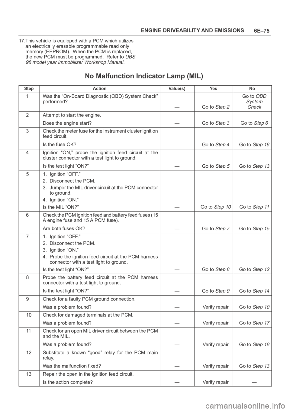
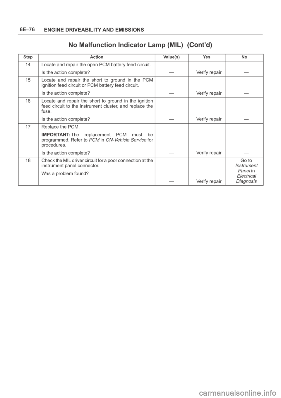
No Malfunction Indicator Lamp (MIL)
D06RW00006
Circuit Description
The “Check Engine” lamp (MIL) should always be
illuminated and steady with the ignition “ON” and the
engine stopped. Ignition feed voltage is supplied to the
MIL bulb through the meter fuse. The powertrain control
module (PCM) turns the MIL “ON” by grounding the MIL
driver circuit.
Diagnostic Aids
An intermittent MIL may be cased by a poor connection,
rubbed-through wire insulation, or a wire broken inside
the insulation. Check for the following items:
Inspect the PCM harness and connections for
improper mating, broken locks, improperly formed or
damaged terminals, poor terminal-to-wire connection,
and damaged harness.
If the engine runs OK, check for a faulty light bulb, an
open in the MIL driver circuit, or an open in the
instrument cluster ignition feed.
If the engine cranks but will not run, check for an open
PCM ignition or battery feed, or a poor PCM to engine
ground.
Test Description
Number(s) below refer to the step number(s) on the
Diagnostic Chart.
2. A “No MIL” condition accompanied by a no-start
condition suggests a faulty PCM ignition feed or
battery feed circuit.
9. Using a test light connected to B+, probe each of the
PCM ground terminals to ensure that a good ground
is present. Refer to
PCM Terminal End View for
terminal locations of the PCM ground circuits.
12.In this step, temporarily substitute a known good
relay for the PCM relay. The horn relay is nearby,
and it can be verified as “good” simply by honking
the horn. Replace the horn relay after completing
this step.
Page 1192 of 6000
6E–75 ENGINE DRIVEABILITY AND EMISSIONS
17.This vehicle is equipped with a PCM which utilizes
an electrically erasable programmable read only
memory (EEPROM). When the PCM is replaced,
the new PCM must be programmed. Refer to
UBS
98 model year Immobilizer Workshop Manual.
No Malfunction Indicator Lamp (MIL)
StepActionVa l u e ( s )Ye sNo
1Was the “On-Board Diagnostic (OBD) System Check”
performed?
—Go to Step 2
Go to OBD
System
Check
2Attempt to start the engine.
Does the engine start?
—Go to Step 3Go to Step 6
3Check the meter fuse for the instrument cluster ignition
feed circuit.
Is the fuse OK?
—Go to Step 4Go to Step 16
4Ignition “ON,” probe the ignition feed circuit at the
cluster connector with a test light to ground.
Is the test light “ON?”
—Go to Step 5Go to Step 13
51. Ignition “OFF.”
2. Disconnect the PCM.
3. Jumper the MIL driver circuit at the PCM connector
to ground.
4. Ignition “ON.”
Is the MIL “ON?”
—Go to Step 10Go to Step 11
6Check the PCM ignition feed and battery feed fuses (15
A engine fuse and 15 A PCM fuse).
Are both fuses OK?
—Go to Step 7Go to Step 15
71. Ignition “OFF.”
2. Disconnect the PCM.
3. Ignition “ON.”
4. Probe the ignition feed circuit at the PCM harness
connector with a test light to ground.
Is the test light “ON?”
—Go to Step 8Go to Step 12
8Probe the battery feed circuit at the PCM harness
connector with a test light to ground.
Is the test light “ON?”
—Go to Step 9Go to Step 14
9Check for a faulty PCM ground connection.
Was a problem found?
—Verify repairGo to Step 10
10Check for damaged terminals at the PCM.
Was a problem found?
—Verify repairGo to Step 17
11Check for an open MIL driver circuit between the PCM
and the MIL.
Was a problem found?
—Verify repairGo to Step 18
12Substitute a known “good” relay for the PCM main
relay.
Was the malfunction fixed?
—Verify repairGo to Step 13
13Repair the open in the ignition feed circuit.
Is the action complete?
—Verify repair—
Page 1193 of 6000
6E–76
ENGINE DRIVEABILITY AND EMISSIONS
No Malfunction Indicator Lamp (MIL)
StepNo Ye s Va l u e ( s ) Action
14Locate and repair the open PCM battery feed circuit.
Is the action complete?
—Verify repair—
15Locate and repair the short to ground in the PCM
ignition feed circuit or PCM battery feed circuit.
Is the action complete?
—Verify repair—
16Locate and repair the short to ground in the ignition
feed circuit to the instrument cluster, and replace the
fuse.
Is the action complete?
—Verify repair—
17Replace the PCM.
IMPORTANT:The replacement PCM must be
programmed. Refer to
PCM in ON-Vehicle Service for
procedures.
Is the action complete?
—Verify repair—
18Check the MIL driver circuit for a poor connection at the
instrument panel connector.
Was a problem found?
—Verify repair
Go to
Instrument
Panel
in
Electrical
Diagnosis
Page 1199 of 6000
6E–82
ENGINE DRIVEABILITY AND EMISSIONS
Engine Cranks But Will Not Run
StepNo Ye s Va l u e ( s ) Action
131. Remove any ignition coil and install a spark tester at
the spark plug end of the coil.
2. Observe the tester while the engine is cranking.
Was a crisp, blue spark observed? Only one or two
sparks followed by no result is considered the same as
“No Spark.”
—Go to Step 15Go to Step 14
14Replace the ignition coil, and return to Step 13 to test
the remaining coils.
Is the action complete?
—Verify repair—
15Repeat Step 13 for each coil. Remove only one coil at a
time, and reinstall each coil on its spark plug after
testing, but do not refasten coils with screws at this
time.
After all coils have passed the spark test, does the
engine start?
—
Refasten all
coils with
their screws
Go to Step 16
161. Remove the spark plugs from all cylinders.
2. Visually inspect the spark plug electrodes.
3. Replace any spark plugs with loose or missing
electrodes or cracked insulators.
Did your inspection reveal any spark plugs exhibiting
excessive fouling?
—
Correct the
fouling
condition
Go to Step 17
17Refer to Engine Mechanical Diagnosis to diagnose the
following conditions:
Faulty or incorrect camshaft drive belts
Leaking or sticky valves or rings
Excessive valve deposits
Loose or worn rocker arms
Weak valve springs
Incorrect valve timing
Leaking head gasket
Is the action complete?
—Verify repairGo to Step 19
18Observe the “Engine Speed” data display on the scan
tool while cranking the engine.
Is the engine RPM indicated? (If the scan tool is
normally powered from the cigarette lighter socket, and
if the scan tool display goes blank while cranking the
engine, it will be necessary to power the scan tool
directly from the vehicle battery.)
—Go to Step 19Go to Step 28
191. Disconnect the 7-pin gray connector at the rear of
the air filter beneath the point where the air duct
attaches to the MAF sensor.
2. Ignition “ON.”
3. Using a test light connected to ground, probe the
ignition terminal at the PCM (female) side of the
7-pin connector.
Is the test light “ON?”
—Go to Step 20Go to Step 26
Page 1203 of 6000
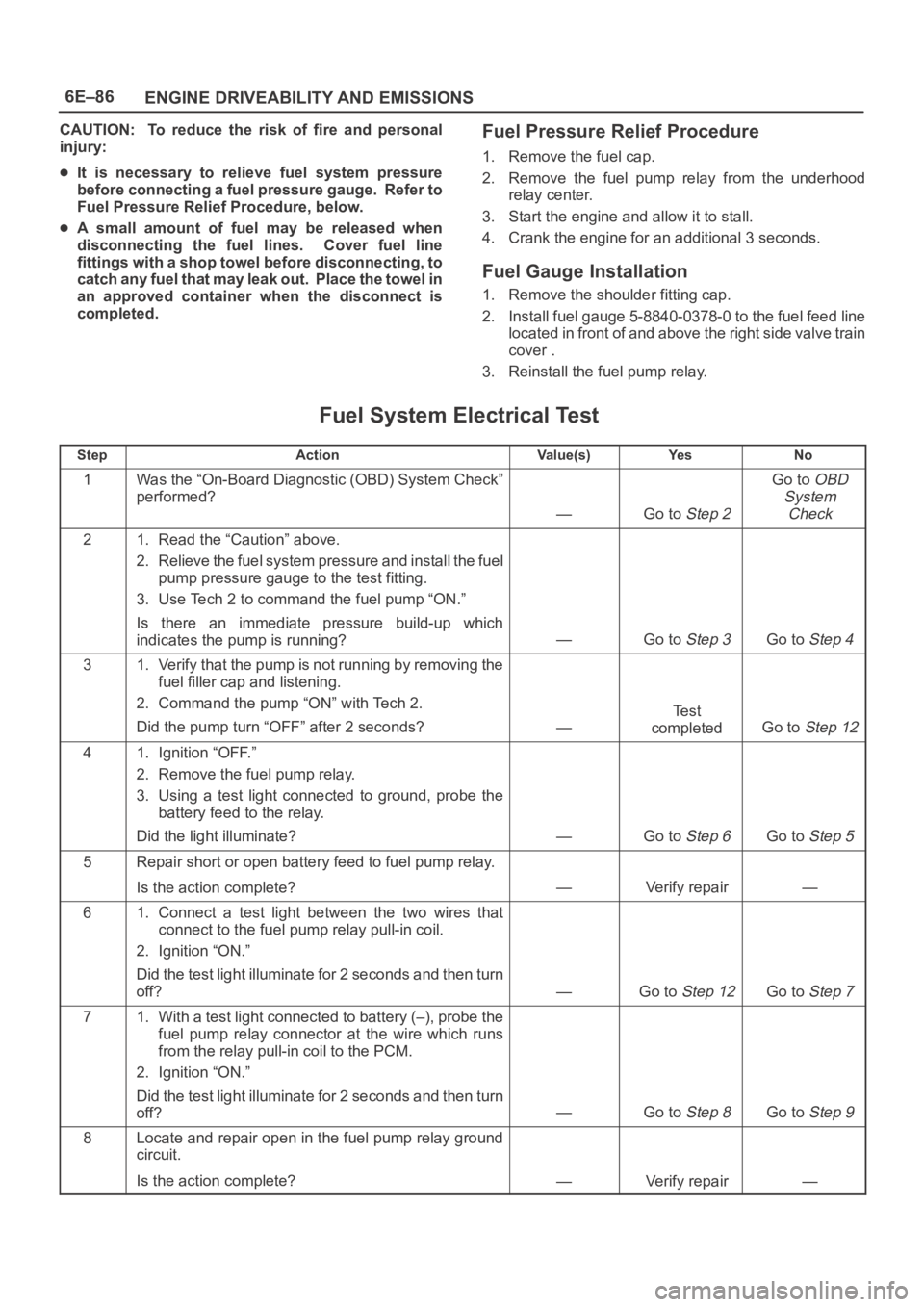
6E–86
ENGINE DRIVEABILITY AND EMISSIONS
CAUTION: To reduce the risk of fire and personal
injury:
It is necessary to relieve fuel system pressure
before connecting a fuel pressure gauge. Refer to
Fuel Pressure Relief Procedure, below.
A small amount of fuel may be released when
disconnecting the fuel lines. Cover fuel line
fittings with a shop towel before disconnecting, to
catch any fuel that may leak out. Place the towel in
an approved container when the disconnect is
completed.
Fuel Pressure Relief Procedure
1. Remove the fuel cap.
2. Remove the fuel pump relay from the underhood
relay center.
3. Start the engine and allow it to stall.
4. Crank the engine for an additional 3 seconds.
Fuel Gauge Installation
1. Remove the shoulder fitting cap.
2. Install fuel gauge 5-8840-0378-0 to the fuel feed line
located in front of and above the right side valve train
cover .
3. Reinstall the fuel pump relay.
Fuel System Electrical Test
StepActionVa l u e ( s )Ye sNo
1Was the “On-Board Diagnostic (OBD) System Check”
performed?
—Go to Step 2
Go to OBD
System
Check
21. Read the “Caution” above.
2. Relieve the fuel system pressure and install the fuel
pump pressure gauge to the test fitting.
3. Use Tech 2 to command the fuel pump “ON.”
Is there an immediate pressure build-up which
indicates the pump is running?
—Go to Step 3Go to Step 4
31. Verify that the pump is not running by removing the
fuel filler cap and listening.
2. Command the pump “ON” with Tech 2.
Did the pump turn “OFF” after 2 seconds?
—
Te s t
completed
Go to Step 12
41. Ignition “OFF.”
2. Remove the fuel pump relay.
3. Using a test light connected to ground, probe the
battery feed to the relay.
Did the light illuminate?
—Go to Step 6Go to Step 5
5Repair short or open battery feed to fuel pump relay.
Is the action complete?
—Verify repair—
61. Connect a test light between the two wires that
connect to the fuel pump relay pull-in coil.
2. Ignition “ON.”
Did the test light illuminate for 2 seconds and then turn
off?
—Go to Step 12Go to Step 7
71. With a test light connected to battery (–), probe the
fuel pump relay connector at the wire which runs
from the relay pull-in coil to the PCM.
2. Ignition “ON.”
Did the test light illuminate for 2 seconds and then turn
off?
—Go to Step 8Go to Step 9
8Locate and repair open in the fuel pump relay ground
circuit.
Is the action complete?
—Verify repair—
Page 1215 of 6000

6E–98
ENGINE DRIVEABILITY AND EMISSIONS
Exhaust Gas Recirculation (EGR) System Check
StepActionVa l u e ( s )Ye sNo
1Check the EGR valve for looseness.
Is the EGR valve Loose?
—Go to Step 2Go to Step 3
2Tighten the EGR valve.
Is the action complete?
—Verify repair—
31. Place the transmission selector in Park or Neutral.
2. Start the engine and idle until warm.
3. Using Tech 2, command EGR “50% ON.”
Does the engine idle rough and lose RPMs?
—
EGR system
working
properly. No
problem
found.
Go to Step 4
41. Engine “OFF.”
2. Ignition “ON.”
3. Using a test light to ground, check the EGR harness
between the EGR valve and the ignition feed.
Does the test light illuminate?
—Go to Step 6Go to Step 5
5Repair the EGR harness ignition feed.
Was the problem corrected?
—Verify repairGo to Step 6
61. Remove the EGR valve.
2. Visually and physically inspect the EGR valve
pintle, valve passages and adapter for excessive
deposits, obstructions or any restrictions.
Does the EGR valve have excessive deposits,
obstructions or any restrictions?
—Go to Step 7Go to Step 8
7Clean or replace EGR system components as
necessary.
Was the problem corrected?
—Verify repairGo to Step 8
81. Ground the EGR valve metal case to battery (–).
2. Using Tech 2, command EGR “ON” and observe the
EGR valve pintle for movement.
Does the EGR valve pintle move according to
command?
—Go to Step 9
Go to DTC
P1406 chart
91. Remove the EGR inlet and outlet pipes from the
intake and exhaust manifolds.
2. Visually and physically inspect manifold EGR ports
and EGR inlet and outlet pipes for blockage or
restriction caused by excessive deposits or other
damage.
Do the manifold EGR ports or inlet and outlet pipes
have excessive deposits, obstructions, or any
restrictions?
—Go to Step 10
EGR system
working
properly. No
problem
found.
10Clean or replace EGR system components as
necessary.
Is the action complete?
—Verify repair—
Page 1221 of 6000

6E–104
ENGINE DRIVEABILITY AND EMISSIONS
Diagnostic Trouble Code (DTC) P0101 MAF System Performance
D06RW103
Circuit Description
The mass air flow (MAF) sensor measures the amount of
air which passes through it into the engine during a given
time. The powertrain control module (PCM) uses the
mass air flow information to monitor engine operating
conditions for fuel delivery calculations. A large quantity
of air entering the engine indicates an acceleration or high
load situation, while a small quantity or air indicates
deceleration or idle.
The MAF sensor produces a frequency signal which can
be monitored using a Tech 2. DTC P0101 will be set if the
signal from the MAF sensor does not match a predicted
value based on throttle position and engine RPM.
Conditions for Setting the DTC
The engine is running.
No TP sensor or MAP sensor DTCs are set.
The throttle is steady, TP angle doesn’t change by
more than 1%.
System voltage is between 11.5 volts and 16 volts.
Calculated air flow is between 25 g/second and 40
g/second.
Above conditions present for at least 1 second.
MAF signal frequency indicates an airflow significantly
higher or lower than a predicted value based on throttle
position and engine RPM for a total of 12.5 seconds
over a 25-second period of time.
Action Taken When the DTC Sets
The PCM will illuminate the malfunction indicator lamp
(MIL) after the second consecutive trip in which the
fault is detected.
The PCM calculates an airflow value based on idle air
control valve position, throttle position, RPM and
barometric pressure.
The PCM will store conditions which were present
when the DTC was set as Freeze Frame and in the
Failure Records data.
Conditions for Clearing the MIL/DTC
DTC P0101 can be cleared by using the Tech 2 “Clear
Info” function or by disconnecting the PCM battery
feed.
Diagnostic Aids
An intermittent may be caused by the following:
Poor connections.
Mis-routed harness.
Rubbed through wire insulation.
Broken wire inside the insulation.
Refer to Intermittents under service category Symptoms.
Any un-metered air may cause this DTC to set. Check for
the following:
The duct work at the MAF sensor for leaks.
An engine vacuum leak.
The PCV system for vacuum leaks.
An incorrect PCV valve.
Page 1224 of 6000
6E–107 ENGINE DRIVEABILITY AND EMISSIONS
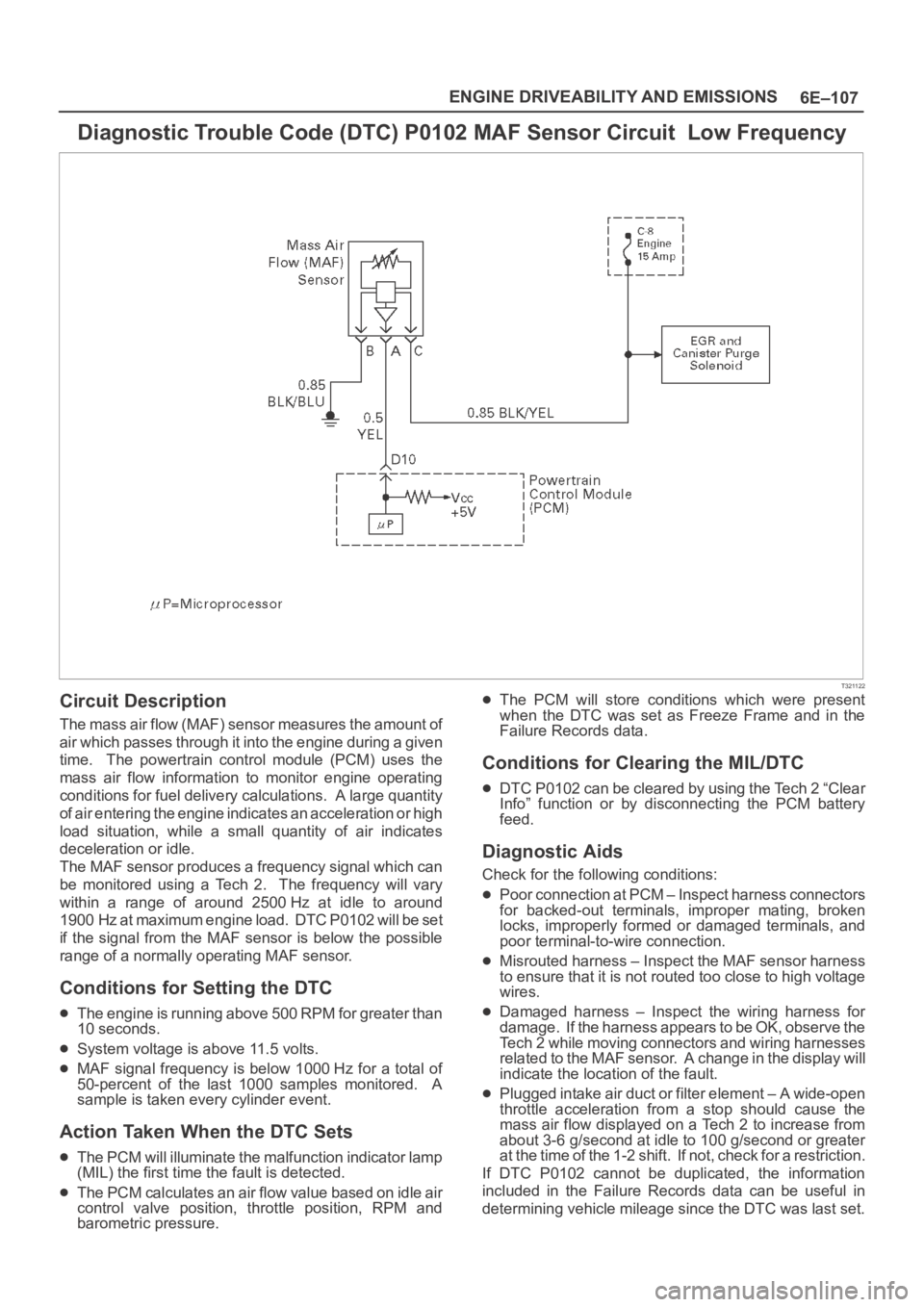
Diagnostic Trouble Code (DTC) P0102 MAF Sensor Circuit Low Frequency
T321122
Circuit Description
The mass air flow (MAF) sensor measures the amount of
air which passes through it into the engine during a given
time. The powertrain control module (PCM) uses the
mass air flow information to monitor engine operating
conditions for fuel delivery calculations. A large quantity
of air entering the engine indicates an acceleration or high
load situation, while a small quantity of air indicates
deceleration or idle.
The MAF sensor produces a frequency signal which can
be monitored using a Tech 2. The frequency will vary
within a range of around 2500 Hz at idle to around
1900 Hz at maximum engine load. DTC P0102 will be set
if the signal from the MAF sensor is below the possible
range of a normally operating MAF sensor.
Conditions for Setting the DTC
The engine is running above 500 RPM for greater than
10 seconds.
System voltage is above 11.5 volts.
MAF signal frequency is below 1000 Hz for a total of
50-percent of the last 1000 samples monitored. A
sample is taken every cylinder event.
Action Taken When the DTC Sets
The PCM will illuminate the malfunction indicator lamp
(MIL) the first time the fault is detected.
The PCM calculates an air flow value based on idle air
control valve position, throttle position, RPM and
barometric pressure.
The PCM will store conditions which were present
when the DTC was set as Freeze Frame and in the
Failure Records data.
Conditions for Clearing the MIL/DTC
DTC P0102 can be cleared by using the Tech 2 “Clear
Info” function or by disconnecting the PCM battery
feed.
Diagnostic Aids
Check for the following conditions:
Poor connection at PCM – Inspect harness connectors
for backed-out terminals, improper mating, broken
locks, improperly formed or damaged terminals, and
poor terminal-to-wire connection.
Misrouted harness – Inspect the MAF sensor harness
to ensure that it is not routed too close to high voltage
wires.
Damaged harness – Inspect the wiring harness for
damage. If the harness appears to be OK, observe the
Tech 2 while moving connectors and wiring harnesses
related to the MAF sensor. A change in the display will
indicate the location of the fault.
Plugged intake air duct or filter element – A wide-open
throttle acceleration from a stop should cause the
mass air flow displayed on a Tech 2 to increase from
about 3-6 g/second at idle to 100 g/second or greater
at the time of the 1-2 shift. If not, check for a restriction.
If DTC P0102 cannot be duplicated, the information
included in the Failure Records data can be useful in
determining vehicle mileage since the DTC was last set.
Page 1225 of 6000

6E–108
ENGINE DRIVEABILITY AND EMISSIONS
Test Description
Number(s) below refer to the step number(s) on the
Diagnostic Chart.
2. This step verifies that the problem is present at idle.4. A voltage reading of less than 4 or over 5 volts at the
MAF sensor signal circuit indicates a fault in the
wiring or a poor connection.
5. This verifies that ignition feed voltage and a good
ground are available at the MAF sensor.
DTC P0102 – MAF Sensor Circuit Low Frequency
StepActionVa l u e ( s )Ye sNo
1Was the “On-Board Diagnostic (OBD) System Check”
performed?
—Go to Step 2
Go to OBD
System
Check
21. Start the engine.
2. With the engine idling, monitor “MAF Frequency”
display on the Tech 2.
Is the “MAF Frequency” below the specified value?
3g/SecGo to Step 4Go to Step 5
31. Ignition “ON,” engine “OFF.”
2. Review and record Tech 2 Failure Records data.
3. Operate the vehicle within Failure Records
conditions as noted.
4. Using a Tech 2, monitor “DTC” info for DTC P0102.
Does the Tech 2 indicate DTC P0102 failed this
ignition?
—Go to Step 4
Refer to
Diagnostic
Aids
41. Ignition “OFF.”
2. Disconnect the MAF sensor connector.
3. Ignition “ON,” engine “OFF.”
4. Using a DVM, measure voltage between the MAF
sensor signal circuit and battery ground.
Is the voltage near the specified value?
5 VGo to Step 5Go to Step 8
5Connect a test light between the MAF sensor ignition
feed and ground circuits at the MAF sensor harness
connector.
Is the test light “ON?”
—Go to Step 13Go to Step 6
6Connect a test light between the MAF sensor ignition
feed circuit and battery ground.
Is the test light “ON?”
—Go to Step 12Go to Step 7
71. Check for a poor connection at the MAF sensor.
2. If a poor connection is found, replace the faulty
terminal(s).
Was a poor connection found?
—Verify repairGo to Step 11
81. Ignition “OFF.”
2. Disconnect the MAF sensor.
3. Disconnect the PCM connector for the MAF signal
circuit.
4. Ignition “ON,” engine “OFF.”
5. With the DVM, measure the voltage between the
MAF signal terminal at the PCM and battery ground.
Is the voltage under the specified value?
4 VGo to Step 9Go to Step 10