engine OPEL GT-R 1973 Service Manual
[x] Cancel search | Manufacturer: OPEL, Model Year: 1973, Model line: GT-R, Model: OPEL GT-R 1973Pages: 625, PDF Size: 17.22 MB
Page 459 of 625
7C- 981973 OPEL SERVICE MANUAL
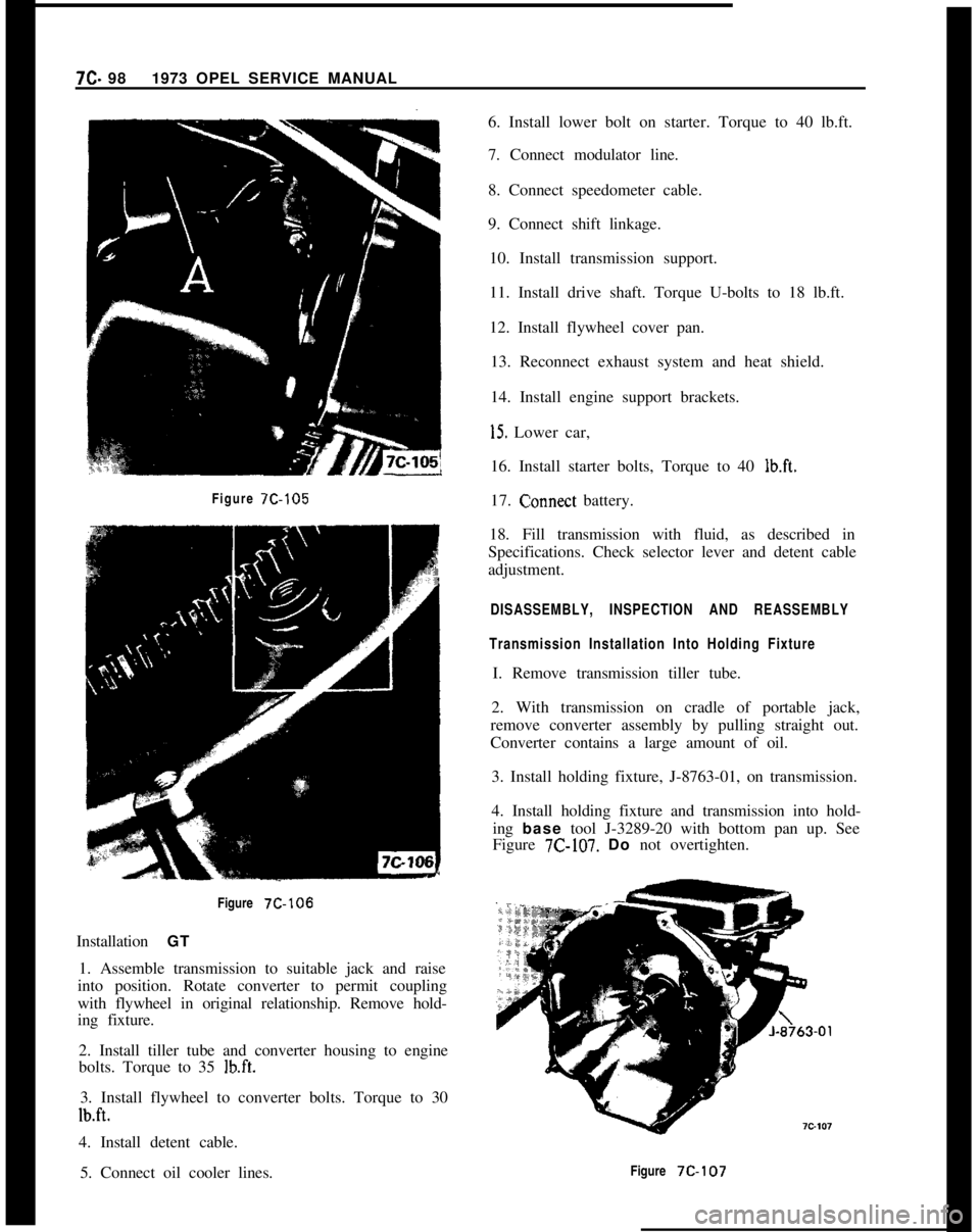
Figure 7C-105Figure
7C-106Installation GT
1. Assemble transmission to suitable jack and raise
into position. Rotate converter to permit coupling
with flywheel in original relationship. Remove hold-
ing fixture.
2. Install tiller tube and converter housing to engine
bolts. Torque to 35
lb.ft.3. Install flywheel to converter bolts. Torque to 30
lb.ft.4. Install detent cable.
5. Connect oil cooler lines.6. Install lower bolt on starter. Torque to 40 lb.ft.
7. Connect modulator line.
8. Connect speedometer cable.
9. Connect shift linkage.
10. Install transmission support.
11. Install drive shaft. Torque U-bolts to 18 lb.ft.
12. Install flywheel cover pan.
13. Reconnect exhaust system and heat shield.
14. Install engine support brackets.
15. Lower car,
16. Install starter bolts, Torque to 40
lb.ft.17.
C:onnect battery.
18. Fill transmission with fluid, as described in
Specifications. Check selector lever and detent cable
adjustment.
DISASSEMBLY, INSPECTION AND REASSEMBLY
Transmission Installation Into Holding FixtureI. Remove transmission tiller tube.
2. With transmission on cradle of portable jack,
remove converter assembly by pulling straight out.
Converter contains a large amount of oil.
3. Install holding fixture, J-8763-01, on transmission.
4. Install holding fixture and transmission into hold-
ing base tool J-3289-20 with bottom pan up. See
Figure
7C-107. Do not overtighten.
Figure
7C-107
Page 495 of 625
7C-1341973 OPEL SERVICE MANUAL
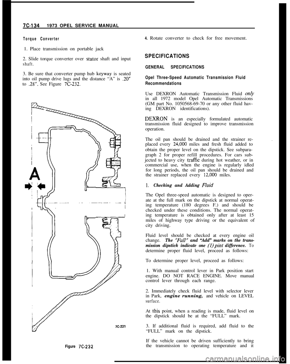
Figure 7C-232
Torque Converter4. Rotate converter to check for free movement.
1. Place transmission on portable jack
2. Slide torque converter over stator shaft and input
shaft.3. Be sure that converter pump hub keyway is seated
into oil pump drive lugs and the distance “A” is
.20”to
.28”. See Figure 7C-232.
SPECIFICATIONS
GENERAL SPECIFICATIONS
Opel Three-Speed Automatic Transmission Fluid
RecommendationsUse DEXRON Automatic Transmission Fluid on/y
in all 1972 model Opel Automatic Transmissions
(GM part No. 1050568-69-70 or any other fluid hav-
ing DEXRON identifications).DEXIRON is an especially formulated automatic
transmission fluid designed to improve transmission
operation.
The oil pan should be drained and the strainer re-
placed every
24,ooO miles and fresh fluid added to
obtain the proper level on the dipstick. See subpara-
graph 2 for proper refill procedures. For cars sub-
jected to heavy city
traff%z during hot weather, or in
commercial use, when the engine is regularly idled
for long periods, the oil pan should be drained and
the strainer replaced every
12,ooO miles.
.
1.Checking and Adding FluidThe Opel three-speed automatic is designed to oper-
ate at the full mark on the dipstick at normal operat-
ing temperature (180 degrees F.) and should be
checked under these conditions. The normal operat-
ing temperature is obtained only after at least 15
miles of highway type driving or the equivalent of
city driving.
Fluid level should be checked at every engine oil
change.
The “FuIl” and “Add” marks on the trans-
mission dipstick indicate one (1)pint
difference. Todetermine proper fluid level, proceed as follows:
To determine proper level, proceed as follows:
1. With manual control lever in Park position start
engine. DO NOT RACE ENGINE. Move manual
control lever through each range.
2. Immediately check fluid level with selector lever
in Park, engine running, and vehicle on LEVEL
surface.At
t,his point, when a reading is made, fluid level on
the dipstick should be at the “FULL” mark.
3. If additional fluid is required, add fluid to the
“FULL” mark on the dipstick.
If the vehicle cannot be driven sufficiently to bring
the transmission to operating temperature and it
Page 496 of 625
AUTOMATIC TRANSMISSION 7C-135
becomes necessary to check the fluid level, the trans-
mission may be checked at room temperature (70
degrees F.) as follows:
1. With manual control lever in Park position start
engine. DO NOT RACE ENGINE. Move manual
control lever through each range.
2. lmmediately check fluid level with selector lever
in Park, engine running, and vehicle on LEVEL sur-
face.At this point, when a reading is made, fluid level on
the dipstick should be I/4” below the “ADD” mark.
3. If additional fluid is required add fluid to bring
level to
l/4” below the “ADD” mark on the dip-
stick.If transmission fluid level is correctly established at
70 degrees F. it will appear at the “FULL” mark on
the dipstick when the transmission reaches normal
operating temperature (180 degrees F.) The fluid
level is set
l/4” below the “ADD” mark on the
dipstick to allow for expansion of the fluid which
occurs as transmission temperatures rise to normal
operating temperature of 180 degrees F.
Do not overfill, as foaming and loss of fluid through
the vent pipe might occur as fluid heats up. If fluid
is too low especially when cold, complete loss
of’drive may result which can cause transmission fail-
ure.
2.Draining oilpan and rep/a&g strainer assembly.
(a) Raise car on hoist or p/ace OnJxk stands, and
provide container to collect draining fluid.
(b) Remove oil pan and gasket. Discard gasket.
(c) Drain fluid from oil pan. Clean pan with solvent
and dry thoroughly with clean compressed air.
(d) Remove strainer assembly, strainer gasket and
discard.
(e) Install new oil strainer gasket. Install new strainer
assembly.
(f) Install new gasket on oil pan and install pan.
Tighten attaching bolts to 7-10 lb. ft.
(g) Lower car and add approximately three (3) pints
of transmission fluid through filler tube.
(h) With manual control lever in Park position, start
engine. DO NOT RACE ENGINE. Move manual
control lever through each range.
(i) Immediately check fluid level with selector leverin Park, engine running, and vehicle on LEVEL
sur-
face.(i) Add additional fluid to bring level to
l/4” below
the “ADD” mark on the dipstick. Do not overfill.
3.Adding Fluid to Fill Dry Transmission and Con-
verter Assembly
The fluid capacity of the Opel Three Speed Auto-
matic transmission and converter assembly is ap-
proximately IO-l/2 pints, but correct level is
determined by the mark on the dipstick rather than
by amount added. In cases of transmission overhaul,
when a complete fill is required, including a new
converter proceed as follows:
(a) Add approximately 10-l/2 pints of transmission
fluid through tiller tube.
The converter should be replaced on any major fail-
ure, such as a clutch or gearset, and an excessive
amount of foreign material is indicated in the pan. If
installation of a new converter is not required add
approximately five (5) pints of transmission fluid.
(b) With manual control lever in Park position start
engine and run at 1000 RPM. DO NOT RACE EN-
GINE. Move manual control lever through each
range.
(c) Immediately check fluid level with selector lever
in Park, engine running, and vehicle on LEVEL
sur-
face.(d) Add additional fluid to bring level to
l/4” below
the “ADD” mark on the dipstick. Do not overfill.
Opel Three Speed Automatic Transmission Towing
Instructions
If an Opel equipped with an automatic transmission
must be towed, the following precautions must be
observed:
The car may be towed safely on its rear wheels with
the shift lever in neutral position at speeds of 35 miles
per hour or less under most conditions.
However, the drive shaft must be disconnected or the
car towed on its front wheels if:
a. Tow speeds in excess of 35 mph are necessary.
b. Car must be towed for extended distances (over 50
miles).
c. Transmission is not operating properly.
If car is towed on its front wheels, the steering wheel
Page 497 of 625
7C-1361973 OPEL SERVICE MANUALshould be secured to keep the front wheels in a
straight-ahead position.sand,. mud, or snow, move the selector lever from
“D” to “R” in a repeat pattern while simultaneously
applying moderate pressure to the accelerator. DoRocking Carnot race engine. Avoid spinning wheels when trying
If it becomes necessary to rock the car to free it fromto free the car.
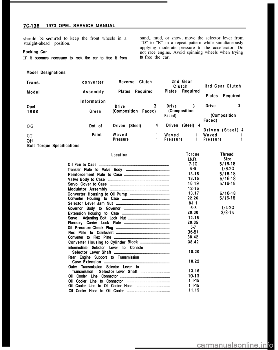
Model DesignationsTrans.
converterReverse Clutch
ModelAssemblyPlates Required2nd Gear
Clutch3rd Gear Clutch
Plates Required
Plates RequiredOpel
1900
OG
GT
CIHInformation
Drive
(Composition Faced:
Drive3Drive3
Green
(Composition
Faced)(CompositionFaced)
Dot ofDriven (Steel)4Driven (Steel) 4
Driven (Steel) 4
PaintWaved1Waved1Waved.1Pressure1Pressure1Pressure1-.
Bolt Torque Specifications
Location
Oil Pan to Case......................................................................Transfer Plate to Valve Body............................................
ReinforcementPlatetoCase..............................................
ValveBodytoCase..............................................................
ServoCovertoCase............................................................
Modulator Assembly............................................................
ConverterHousingtoOilPump........................................
Converter Housing to Case................................................
Selector Lever Jam Nut......................................................
Governor Body to Governor..............................................
ExtensionHousing to Case................................................
Servo AdjustingBolt Lock Nut..........................................
Planetary Carrier Lock Plate..............................................
OilPressureCheckPlug......................................................
Flex Plate to Crankshaft......................................................
Converter to Flex Plate........................................................
ConverterHousingtoCylinderBlock..............................
intermediate Selector Lever to Console
Selector Lever Shaft........................................................
Rear Engine Support to Transmission
CaseExtension..................................................................
Outer Transmission Selector Lever to
TransmissionSelectorLeverShaft..............................
Oil Cooler Line Connector..................................................
Oil Cooler Line to Connector............................................
Oil Cooler Line to Oil Cooler Hose..................................
Oil Cooler Hose to Oil Cooler............................................
Torque
Lb.Ft.7-10
6-8
13.15
13.1516-1812.15
13.17
22.26
8-l 1
6-8
20.30
12.15
20.35
5-736.5
138.42
38.42
Thread
Size
5/16-18
l/6-20
5/16-18
5/16-18
5/16-18
5/16-18
5/16-18
l/4-20
3/8-l 6
18.20
18.22
13.1610-13
1 l-15
1 l-15
11.15
Page 504 of 625

HOOD, FENDERS, AND GRILLE8A- 3
2. Adjust headlamps to lock or unlock simultane-
ously by adjusting lock nut (B). See Figure EA-1.3. Adjust headlamp assembly in opening as follows:
a. To align front of assembly vertically or horizon-
tally, loosen bolts indicated (A) in Figure 8A- 2.
b. To align front of assembly longitudinally, loosen
lock nut (B) in Figure 8A-2 and bolts marked (B) in
Figure
8A-3.c. To align rear of assembly vertically loosen bolts
indicated (A) in Figure
8A-3.MAJOR
REPAIR
REMOVAL AND INSTALLATION OF HOOD1. With a pencil, mark hinge positions on engine
hood. See Figure
SA-4.Figure EA.2 Headlamp Assembly Front Adjustment
LocationFigure
CIA-3 Headlamp Assembly Rear AdjustmentLocationFigure
CIA-4 Marking Hinge Position
2. Unscrew engine hood bolts from hinges. Hood
must be aligned so that the distances to the
adjacent surfaces are almost equal all around.
REMOVAL AND INSTALLATION OF FENDER
(OPEL 1900. MANTA)
1. Remove and install front bumper.
2. Remove and install radiator grille.
3. Remove and install headlamp covering.
4. Remove and install side panel trim pad.
5. Remove and install hood catch.
6. Remove and install rubber bumper (hood rest).
7. If required, remove and install direction signal
lamp.
8, Unscrew attaching bolts at fender circumference
and remove fender. See Figure
8A-5.
Page 505 of 625

8A.41973 OPEL SERVICE MANUAL
Figure SA-5 Location of Fender Attaching Bolts
9. Fit new fender and apply a sealing compound, as
required, to joint. See Figure
SA-6.Figure 8A-6 Sealing Location
10. Coat fender inside with a dampening compound.
REMOVAL AND INSTALLATION OF HEADLAMP
COVERING (OPEL
1900. MANTA)
Removal1. Remove radiator grille.2. In engine compartment unscrew headlamp cover-
ing.
Se:e Figure SA-7.Figure 8A-7 Headlamp Covering Attaching Bolts
Installation1. Install headlamp covering. See Figure
SA-7.2. Install radiator grille.
REMOVAL AND INSTALLATION OF HEADLAMP
ASSEMBLY
(GT)1. Move headlamp to open position and remove
headlamp cover. See Figure
SA-8.Figure EA.8 Removing Headlamp Cap
Page 514 of 625

HEATER SYSTEM - GT9A- 5
MAJOR REPAIR
REMOVAL AND INSTALLATION INSTRUMENT
PANEL FRESH AIR OUTLET
Removal
1. Remove instrument panel cover assembly. Refer
to Group 1.
2. Snap grille out of outlet.
3. Remove knob from lever and remove outlet.
Installation
1. Install outlet and knob onto lever.
2. Snap grille into outlet.
3.
Install instrument panel cover assembly. Refer to
Group 1.
REMOVAL AND INSTALLATION KICK PANEL
FRESH AIR OUTLET
Removal
Using a screwdriver, carefully pry out outlet.
Installation
Install outlet.
REMOVAL AND INSTALLATION BLOWER
SWITCH
Removal
i. Remove instrument panel assembly. Refer to
Group 1.
2. Unscrew switch assembly from panel.
Installation
1. Screw switch assembly to instrument panel.
2. Install instrument panel assembly. Refer to Group
1.
REMOVAL AND INSTALLATION HEATER
Ramova!
1. Remove lower radiator hose, drain, and collect
coolant. 2. Detach coolant feed (A) and return (B) hoses, in
engine compartment from heater core. See Figure
9A-5.
Figure 9A-5 Heater Hose Connections
3. In engine compartment remove hood lock control
cable retaining clip and cable from lock bar. See Figure
9A-6.
Figure 9A-6 Hood Release Control Cable
4. Remove console shift cover between seats using
the following instructions:
a. Remove ash tray and remove two screws under it.
Page 517 of 625
9A-8 1973 OPEL SERVICE MANUAL
Installation
1. Install heater blower and case assembly, securing
with one (1) bolt at the top and two (2) nuts from the
bottom. See Figure
9A-15.
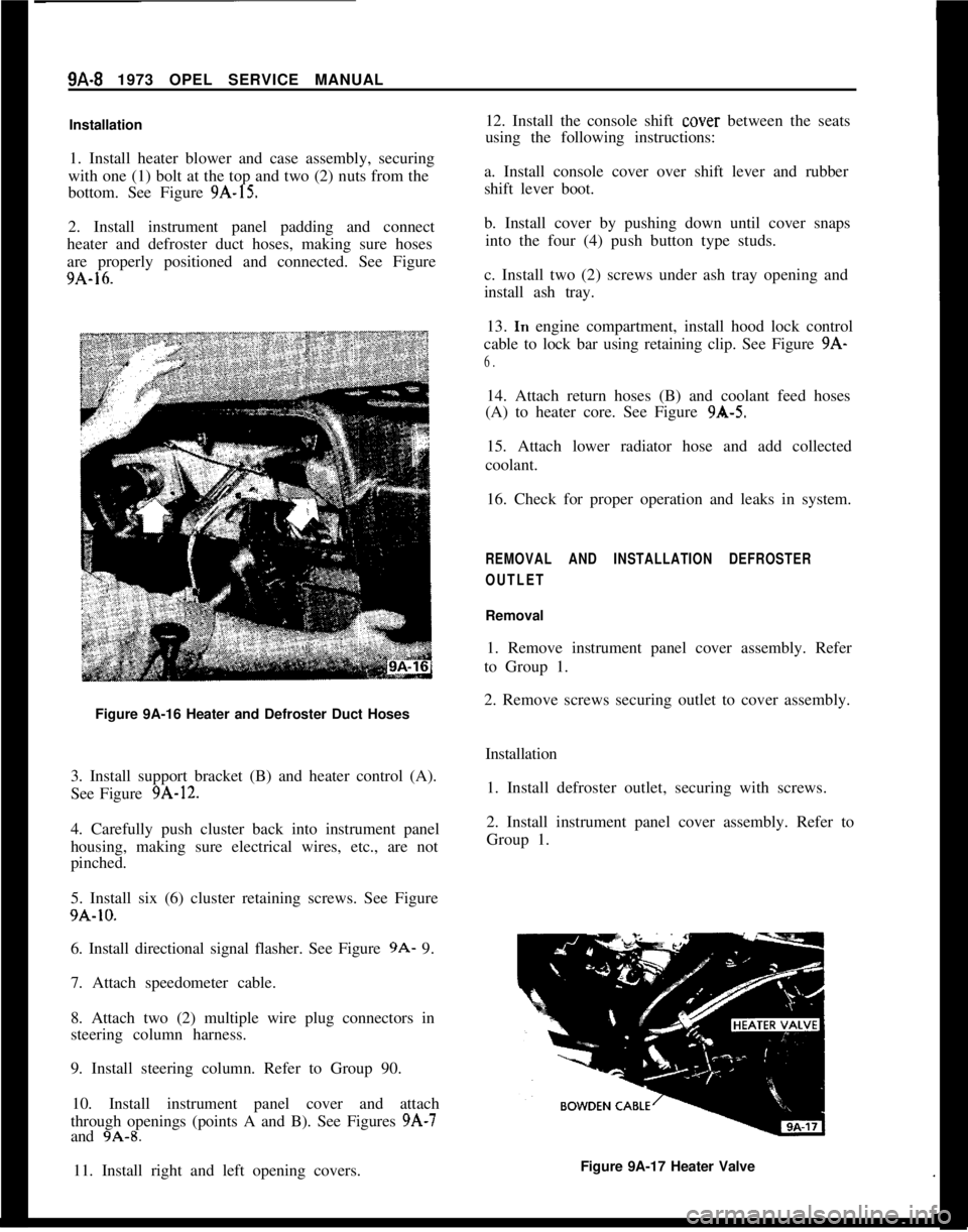
2. Install instrument panel padding and connect
heater and defroster duct hoses, making sure hoses
are properly positioned and connected. See Figure
9A-16.
Figure 9A-16 Heater and Defroster Duct Hoses
3. Install support bracket (B) and heater control (A).
See Figure
9A-12.
4. Carefully push cluster back into instrument panel
housing, making sure electrical wires, etc., are not
pinched.
5. Install six (6) cluster retaining screws. See Figure
9A-10.
6. Install directional signal flasher. See Figure
9A- 9.
7. Attach speedometer cable.
8. Attach two (2) multiple wire plug connectors in
steering column harness.
9. Install steering column. Refer to Group 90.
10. Install instrument panel cover and attach
through openings (points A and B). See Figures
9A-7
and 9A-8.
11. Install right and left opening covers. 12. Install the console shift
cover
between the seats
using the following instructions:
a. Install console cover over shift lever and rubber
shift lever boot.
b. Install cover by pushing down until cover snaps into the four (4) push button type studs.
c. Install two (2) screws under ash tray opening and
install ash tray. 13.
In engine compartment, install hood lock control
cable to lock bar using retaining clip. See Figure
9A-
6.
14. Attach return hoses (B) and coolant feed hoses
(A) to heater core. See Figure
9A-5.
15. Attach lower radiator hose and add collected
coolant.
16. Check for proper operation and leaks in system.
REMOVAL AND INSTALLATION DEFROSTER
OUTLET
Removal
1. Remove instrument panel cover assembly. Refer
to Group 1.
2. Remove screws securing outlet to cover assembly.
Installation1. Install defroster outlet, securing with screws.
2. Install instrument panel cover assembly. Refer to
Group 1.
Figure 9A-17 Heater Valve
Page 518 of 625

HEATER SYSTEM. GT9A- 9
REMOVAL AND INSTALLATION HEATER VALVE
Removal
1. Remove lower radiator hose and drain and collect
coolant.
2. Disconnect control cable.
3. Loosen heater hose clamps and remove valve from
hoses. See Figure 9A-17.SPECIFICATIONS
EngineRecommended Coolant
.__,.__...._...__.,.,...,......Thermostat Opens At (Degrees) F.
..__..___...Installation
1. Install valve into heater hoses and install hose
clamps.
2. Connect control cable.
3. Install lower radiator hose and add collected coo-
lant.
.....................................Ethylene-Glycol Base
...................................................................189Cooling
SystemCapacity(WithHeater)..........................................................................6Qt.BlowerMotorType
......................................................................................................12VDC
BlowerFanType
..................................................................................................SquirrelCage
Page 520 of 625

HEATER SYSTEM. OPEL 1900. MANTA9A- 11air is attained, as the water does not cool down in the
second part of the core.
A Water Outlet
B Water Inlet
The center lever actuates the two-stage blower mo-
tor.Lever positions:
Left to Center
- Motor Switched Off
Right of Center
- Lo Blower
Right
- Hi Blower
The lower lever opens and closes the air door which
channels the air flow to either the lower heater out-
lets or to the defroster outlets.
In the left lever position, the air inlet is closed. Up
to the center position, the air is directed
t,o the lower
heater outlets.
When moving the lever from center position towards
the right, the air flow to the lower
heatezr outlets is
reduced and increased to the defroster
csutlets.With the lever in its right position, the air is directed
to the defroster outlets only. For windshield defrost-
ing, all levers have to be moved to the right.
FUNCTION OF THE HEATER AND VENTILATION
SYSTEMThe engine hood is provided with slots in front of the
windshield. The air is directed through the slots into
the heater housing located in the engine compart-
ment, flows into the air distributor housing, and
from there to the lower heater outlets and,/or defros-
ter outlets, depending on the position of the control.
The two-stage blower motor is arranged in the heater
housing above the heater core and actuated by the
center control. The blower motor draws in the air
entering through the slots, blows the air through the
heater core into the air distributor housin:?, and from
there to the lower heater outlets and/or defroster
outlets, depending on the position of the lower con-
trol. See Figure 9A-32.
The heater valve regulates the flow of coolant
through the heater core, thereby varying
t:he temper-
ature of the air flow past the core.
The ventilation of vehicle interior is completed by a
draft-free air circulation pattern. Vent
slots are ar-
ranged below the back window which
are: connected
through channels to the rear quarter
iside panel.
From here, the inside air escapes into
the! open. TheFigure
9A-32 Air Flow
head wind (caused by the car traveling down the
road) promotes this process so that there is always
fresh air in vehicle interior.
On the Model 54 Station Wagon, there will be no air
outlets in the rear. For adequate flow-through type
ventilation, it will be necessary to open a rear win-
dow.Aside from the fresh air admission through the
heater system, two fresh air inlet nozzles are ar-
ranged in the center of the instrument panel. These
nozzles can be turned to direct the air flow in the
desired direction. In addition, rotary flaps allow the
regulation of the entering air or to shut off the air
completely.
These nozzles admit unheated fresh air only and
operate independent of the heater and defroster sys-
tem.
DIAGNOSIS
HEATER SYSTEM TROUBLE DIAGNOSIS
TROUBLETemperature of heated air at outlets too low.
CAUSE AND CORRECTIONCheck radiator cap for proper sealing action. Re-
place, if necessary.
Check for adequate coolant supply. If level is down,
correct cause of coolant loss and refill radiator.
Inspect hose for kinks. Relieve kink or replace hoses.
Check thermostat operation by measuring tempera-
ture of coolant at radiator. Temperature should be
within 5 degrees F. of thermostat rated value (189
degrees F.).