engine OPEL GT-R 1973 Service Manual
[x] Cancel search | Manufacturer: OPEL, Model Year: 1973, Model line: GT-R, Model: OPEL GT-R 1973Pages: 625, PDF Size: 17.22 MB
Page 401 of 625
7C- 401973 OPEL SERVICE MANUAL
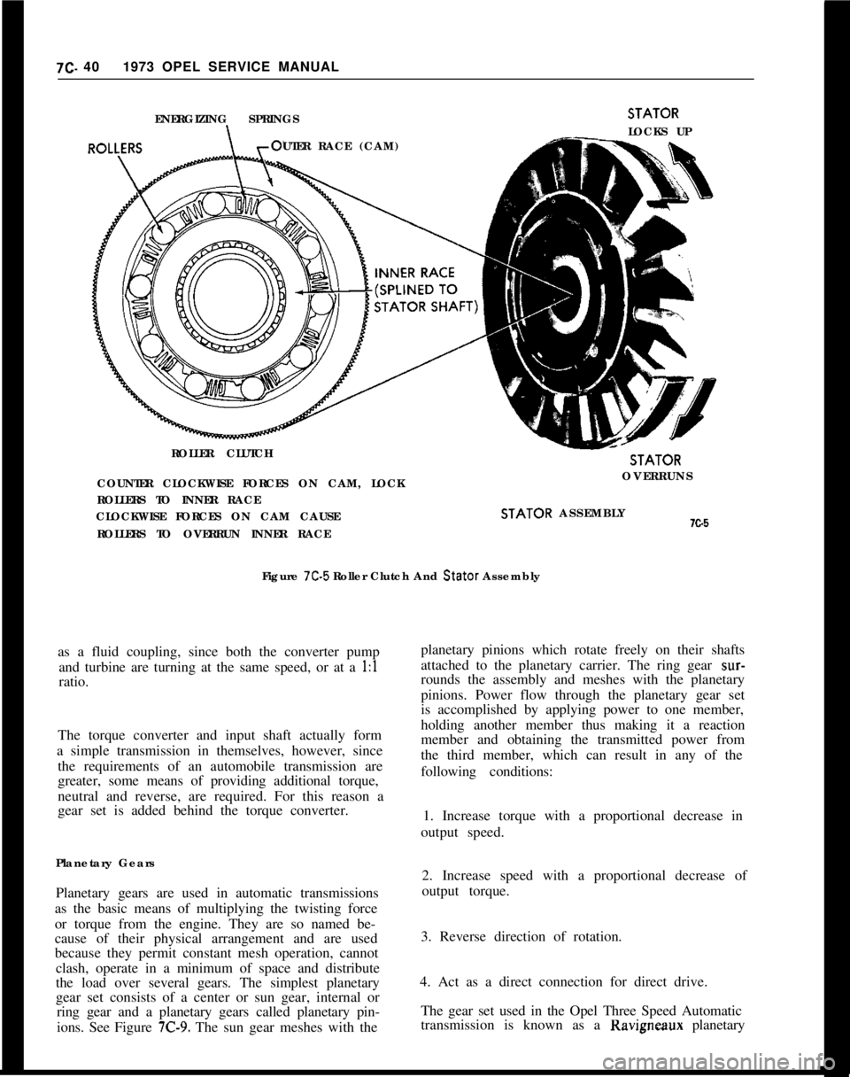
ENERGIZING SPRINGS
UTER RACE (CAM)
ROLLER CLUTCHSTATOR
LOCKS UPSTATOR
COUNTER CLOCKWISE FORCES ON CAM, LOCKOVERRUNS
ROLLERS TO INNER RACE
CLOCKWISE FORCES ON CAM CAUSESTATOR ASSEMBLYx.5
ROLLERS TO OVERRUN INNER RACE
Figure 7C-5 Roller Clutch And Stator Assembly
as a fluid coupling, since both the converter pump
and turbine are turning at the same speed, or at a 1:l
ratio.
The torque converter and input shaft actually form
a simple transmission in themselves, however, since
the requirements of an automobile transmission are
greater, some means of providing additional torque,
neutral and reverse, are required. For this reason a
gear set is added behind the torque converter.
Planetary Gears
Planetary gears are used in automatic transmissions
as the basic means of multiplying the twisting force
or torque from the engine. They are so named be-
cause of their physical arrangement and are used
because they permit constant mesh operation, cannot
clash, operate in a minimum of space and distribute
the load over several gears. The simplest planetary
gear set consists of a center or sun gear, internal or
ring gear and a planetary gears called planetary pin-
ions. See Figure
7C-9. The sun gear meshes with theplanetary pinions which rotate freely on their shafts
attached to the planetary carrier. The ring gear
sur-rounds the assembly and meshes with the planetary
pinions. Power flow through the planetary gear set
is accomplished by applying power to one member,
holding another member thus making it a reaction
member and obtaining the transmitted power from
the third member, which can result in any of the
following conditions:
1. Increase torque with a proportional decrease in
output speed.
2. Increase speed with a proportional decrease of
output torque.
3. Reverse direction of rotation.
4. Act as a direct connection for direct drive.
The gear set used in the Opel Three Speed Automatic
transmission is known as a Ravigneaux planetary
Page 405 of 625
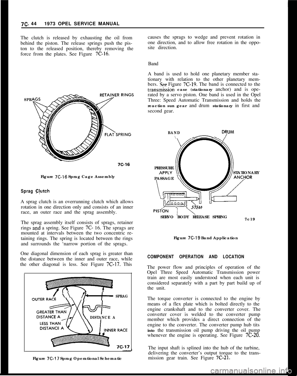
causes the sprags to wedge and prevent rotation in
one direction, and to allow free rotation in the oppo-
site direction.7C. 441973 OPEL SERVICE MANUAL
The clutch is released by exhausting the oil from
behind the piston. The release springs push the pis-
ton to the released position, thereby removing the
force from the plates. See Figure 7C-16.Band
A band is used to hold one planetary member sta-
tionary with relation to the other planetary mem-
bers.
!See Figure 7C-19. The band is connected to the
SPR
7C-16Figure
7C-16 Sprag Cage Assembly
Sprag C(utchA sprag clutch is an overrunning clutch which allows
rotation in one direction only and consists of an inner
race, an outer race and the sprag assembly.
The sprag assembly itself consists of sprags, retainer
rings and a spring. See Figure 7C- 16. The sprags are
mounted at intervals between the two concentric re-
taining rings. The spring is located between the rings
and surrounds the ‘narrow portion of the sprags.
One diagonal dimension of each sprag is greater than
the distance between the inner and outer race, while
the other diagonal is less. See Figure
7C-17. This
\ \I’b+ SPRAG
DISTANCE AFigure
7C-17 Sprag Operational Schematictransmissio; case (stationary anchor) and is ope-
rated by a servo piston. One band is used in the Opel
Three: Speed Automatic Transmission and holds the
reaction sun gear and drum stationary in first and
second gear.
BAND\- D7uM
PRESSURE
STATIONARY
PASSAGE
yPlSfON
1 y””SERVO BODY RELEASE SPRING
7c19
Figure
7C-19 Band Application
COMPONENT OPERATION AND LOCATIONThe power flow and principles of operation of the
Opel Three Speed Automatic Transmission power
train are most easily understood when each unit is
considered separately with a part by part build up of
the unit.
The torque converter is connected to the engine by
means of a flex plate which is bolted directly to the
engine crankshaft and to the converter cover. The
converter cover is welded to the converter pump
member which provides a direct connection of the
engine to the converter. The converter pump hub tits
into the transmission oil pump driving the oil pump
whenever the engine is operating. See Figure
7C-20.The input shaft is splined into the hub of the turbine,
delivering the converter’s output torque to the trans-
mission gear train. See Figure
7C-21.
Page 409 of 625
7C- 481973 OPEL SERVICE MANUAL
INPUT SUNRING
GEAR ASSY.GEARPLANETARY
CARRIERASSY.REACTION SUNtow
GEAR 8 DRUMBAND
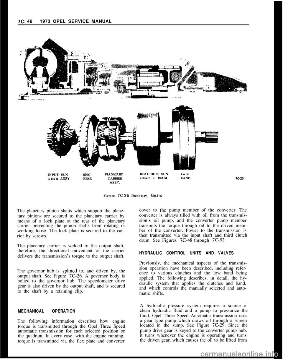
Figure 7C-25Planetary Gears
The planetary pinion shafts which support the plane-
tary pinions are secured to the planetary carrier by
means of a lock plate at the rear of the planetary
carrier preventing the pinion shafts from rotating or
working loose. The lock plate is secured to the car-
rier by screws.
The planetary carrier is welded to the output shaft,
therefore, the directional movement of the carrier
delivers the transmission’s torque to the output shaft.
The governor hub is splined to, and driven by, the
output shaft. See Figure 7C-26. A governor body is
bolted to the governor hub. The speedometer drive
gear is also driven by the output shaft, and is secured
to the shaft by a retaining clip.
MECHANICAL OPERATIONThe following information describes how engine
torque is transmitted through the Opel Three Speed
automatic transmission for each selected position on
the quadrant. In every case, with the engine running,
torque is transmitted via the flex plate and converter7G25
cover to
tht? pump member of the converter. The
converter is always tilled with oil from the transmis-
sion’s oil pump, and the converter pump member
transmits the torque through oil to the driven mem-
ber of the converter. Power to the transmission is
then transmitted via the input shaft and third clutch
drum. See Figures
7C-48 through 7C-52.
HYDRAULIC CONTROL UNITS AND VALVESPreviously, the mechanical aspects of the transmis-
sion operation have been described, including refer-
ence to various clutches and the low band being
applied. The following describes, in detail, the hy-
draulic system that applies the clutches and band,
and which controls the manually selected and auto-
matic shifts.
A hydraulic pressure system requires a source of
clean hydraulic fluid and a pump to pressurize the
fluid. Opel Three Speed Automatic transmission uses
a gear type pump which draws oil through a screen
located in the sump. See Figure
7C-29. Since the
pump drive gear is keyed to the converter pump hub,
it turns whenever the engine is operating and turns
the driven gear, which causes the oil to be lifted from
Page 411 of 625
712.501973 OPEL SERVICE MANUAL
3. Detent pressure regulator valve.
4. 1 - 2 Accumulator valve.
5. Governor.
B. Selector valves (manually and hydraulically con-
trolled).
I. Manual valve.
2. Detent valve.
3. 1
- 2 Shift valve.
4. 2
- 3 Shift valve.
5. 3
- 2 Downshift control valve.
6. Manual low and reverse control valve.
7. Boost control valve.
C. Timing Valves.
1. Low speed downshift timing valve.
2. High speed downshift timing valve.
3. Second clutch orifice valve.
D. Accumulators.
1. 1
- 2 Accumulator.
2. Low servo piston.
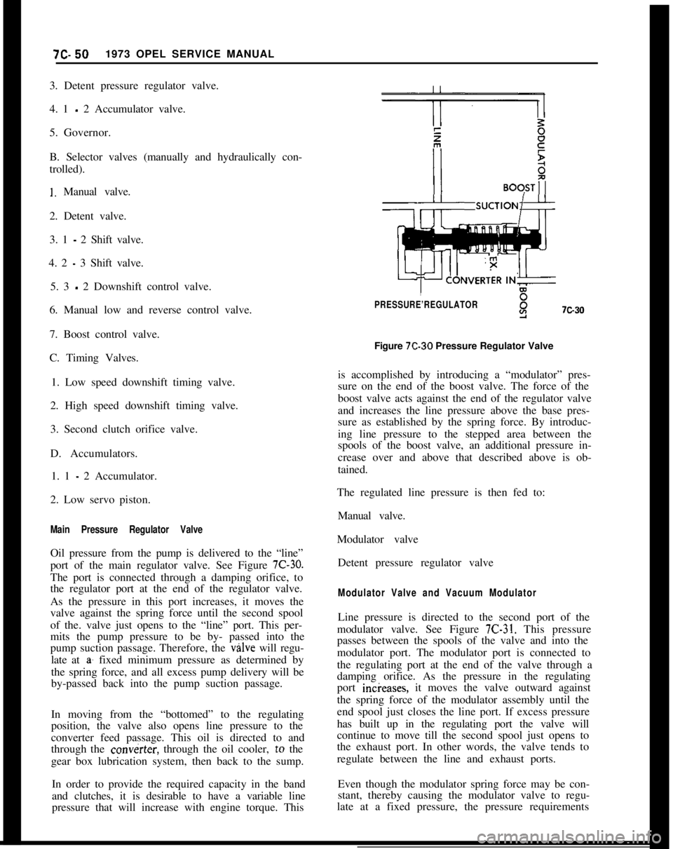
Main Pressure Regulator ValveOil pressure from the pump is delivered to the “line”
port of the main regulator valve. See Figure
7C-30.The port is connected through a damping orifice, to
the regulator port at the end of the regulator valve.
As the pressure in this port increases, it moves the
valve against the spring force until the second spool
of the. valve just opens to the “line” port. This per-
mits the pump pressure to be by- passed into the
pump suction passage. Therefore, the valve will regu-
late at
a’ fixed minimum pressure as determined by
the spring force, and all excess pump delivery will be
by-passed back into the pump suction passage.
In moving from the “bottomed” to the regulating
position, the valve also opens line pressure to the
converter feed passage. This oil is directed to and
through the
cow&x, through the oil cooler, to the
gear box lubrication system, then back to the sump.
In order to provide the required capacity in the band
and clutches, it is desirable to have a variable line
pressure that will increase with engine torque. This
PRESSURE’REGULATORY7c30Figure 7C-30 Pressure Regulator Valve
is accomplished by introducing a “modulator” pres-
sure on the end of the boost valve. The force of the
boost valve acts against the end of the regulator valve
and increases the line pressure above the base pres-
sure as established by the spring force. By introduc-
ing line pressure to the stepped area between the
spools of the boost valve, an additional pressure in-
crease over and above that described above is ob-
tained.
The regulated line pressure is then fed to:
Manual valve.
Modulator valve
Detent pressure regulator valve
Modulator Valve and Vacuum ModulatorLine pressure is directed to the second port of the
modulator valve. See Figure
7C-31. This pressure
passes between the spools of the valve and into the
modulator port. The modulator port is connected to
the regulating port at the end of the valve through a
damping orifice. As the pressure in the regulating
port incieases, it moves the valve outward against
the spring force of the modulator assembly until the
end spool just closes the line port. If excess pressure
has built up in the regulating port the valve will
continue to move till the second spool just opens to
the exhaust port. In other words, the valve tends to
regulate between the line and exhaust ports.
Even though the modulator spring force may be con-
stant, thereby causing the modulator valve to regu-
late at a fixed pressure, the pressure requirements
Page 412 of 625
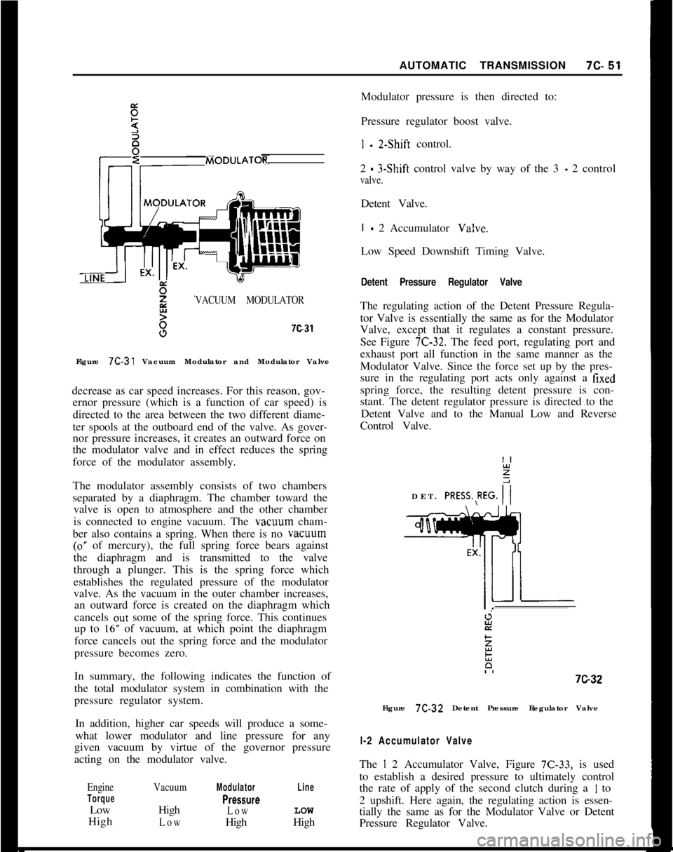
AUTOMATIC TRANSMISSION7c-51VACUUM MODULATOR7c31
Figure 7C-31 Vacuum Modulator and Modulator Valve
decrease as car speed increases. For this reason, gov-
ernor pressure (which is a function of car speed) is
directed to the area between the two different diame-
ter spools at the outboard end of the valve. As gover-
nor pressure increases, it creates an outward force on
the modulator valve and in effect reduces the spring
force of the modulator assembly.
The modulator assembly consists of two chambers
separated by a diaphragm. The chamber toward the
valve is open to atmosphere and the other chamber
is connected to engine vacuum. The vacwm cham-
ber also contains a spring. When there is no vacuum
(0” of mercury), the full spring force bears against
the diaphragm and is transmitted to the valve
through a plunger. This is the spring force which
establishes the regulated pressure of the modulator
valve. As the vacuum in the outer chamber increases,
an outward force is created on the diaphragm which
cancels out some of the spring force. This continues
up to
16” of vacuum, at which point the diaphragm
force cancels out the spring force and the modulator
pressure becomes zero.
In summary, the following indicates the function of
the total modulator system in combination with the
pressure regulator system.
In addition, higher car speeds will produce a some-
what lower modulator and line pressure for any
given vacuum by virtue of the governor pressure
acting on the modulator valve.
Engine
TorqueLow
High
VacuumHigh
Low
Modulator
PreSSWe
LowHigh
LineLOW
HighModulator pressure is then directed to:
Pressure regulator boost valve.
I - 2.Shift control.
2
- 3-Shift control valve by way of the 3 - 2 control
valve.Detent Valve.
I - 2 Accumulator Va!ve.
Low Speed Downshift Timing Valve.
Detent Pressure Regulator ValveThe regulating action of the Detent Pressure Regula-
tor Valve is essentially the same as for the Modulator
Valve, except that it regulates a constant pressure.
See Figure
7C-32. The feed port, regulating port and
exhaust port all function in the same manner as the
Modulator Valve. Since the force set up by the pres-
sure in the regulating port acts only against a
fixedspring force, the resulting detent pressure is con-
stant. The detent regulator pressure is directed to the
Detent Valve and to the Manual Low and Reverse
Control Valve.
DET. PRESS.,REG.
i7G3-2
Figure 7C-32 Detent Pressure Regulator Valve
l-2 Accumulator ValveThe
I 2 Accumulator Valve, Figure 7C-33, is used
to establish a desired pressure to ultimately control
the rate of apply of the second clutch during a
I to
2 upshift. Here again, the regulating action is essen-
tially the same as for the Modulator Valve or Detent
Pressure Regulator Valve.
Page 413 of 625
7C- 521973 OPEL SERVICE MANUAL
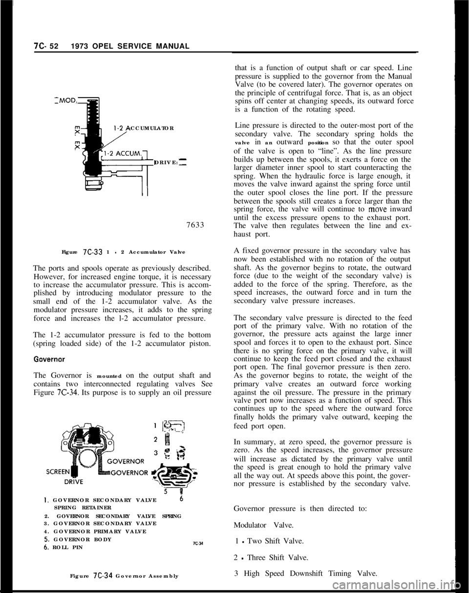
CCUMULATOR
DRIVE:--7633
Figure 7C-33 1
- 2 Accumulator Valve
The ports and spools operate as previously described.
However, for increased engine torque, it is necessary
to increase the accumulator pressure. This is accom-
plished by introducing modulator pressure to the
small end of the 1-2 accumulator valve. As the
modulator pressure increases, it adds to the spring
force and increases the l-2 accumulator pressure.
The 1-2 accumulator pressure is fed to the bottom
(spring loaded side) of the 1-2 accumulator piston.
The Governor is mounted on the output shaft and
contains two interconnected regulating valves See
Figure
7C-34. Its purpose is to supply an oil pressure
5 8I. GOVERNOR SECONDARY VALVE6
SPRING RETAINER
2. GOVERNOR SECONDARY VALVE SPRING
3. GOVERNOR SECONDARY VALVE
4. GOVERNOR PRIMARY VALVE
5. GOVERNOR BODY6. ROLL PINIC~VFigure 7C-34 Governor Assemblythat is a function of output shaft or car speed. Line
pressure is supplied to the governor from the Manual
Valve (to be covered later). The governor operates on
the principle of centrifugal force. That is, as an object
spins off center at changing speeds, its outward force
is a function of the rotating speed.
Line pressure is directed to the outer-most port of the
secondary valve. The secondary spring holds the
valve in an outward position so that the outer spool
of the valve is open to “line”. As the line pressure
builds up between the spools, it exerts a force on the
larger diameter inner spool to start counteracting the
spring. When the hydraulic force is large enough, it
moves the valve inward against the spring force until
the outer spool closes the line port. If the pressure
between the spools still creates a force larger than the
spring force, the valve will continue to move inward
until the excess pressure opens to the exhaust port.
The valve then regulates between the line and ex-
haust port.
A fixed governor pressure in the secondary valve has
now been established with no rotation of the output
shaft. As the governor begins to rotate, the outward
force (due to the weight of the secondary valve) is
added to the force of the spring. Therefore, as the
speed increases, the outward force and in turn the
secondary valve pressure increases.
The secondary valve pressure is directed to the feed
port of the primary valve. With no rotation of the
governor, the pressure acts against the large inner
spool and forces it to open to the exhaust port. Since
there is no spring force on the primary valve, it will
continue to keep the feed port closed and the exhaust
port open. The final governor pressure is then zero.
As the governor begins to rotate, the weight of the
primary valve creates an outward force working
against the oil pressure. The pressure in the primary
valve port now increases as a function of speed. This
continues up to the speed where the outward force
finally holds the primary valve outward, keeping the
feed port open.
In summary, at zero speed, the governor pressure is
zero. As the speed increases, the governor pressure
will increase as dictated by the primary valve until
the speed is great enough to hold the primary valve
all the way out. At speeds above this point, the gover-
nor pressure is established by the secondary valve.
Governor pressure is then directed to:
Modulator Valve.
1 - Two Shift Valve.
2
- Three Shift Valve.
3 High Speed Downshift Timing Valve.
Page 417 of 625
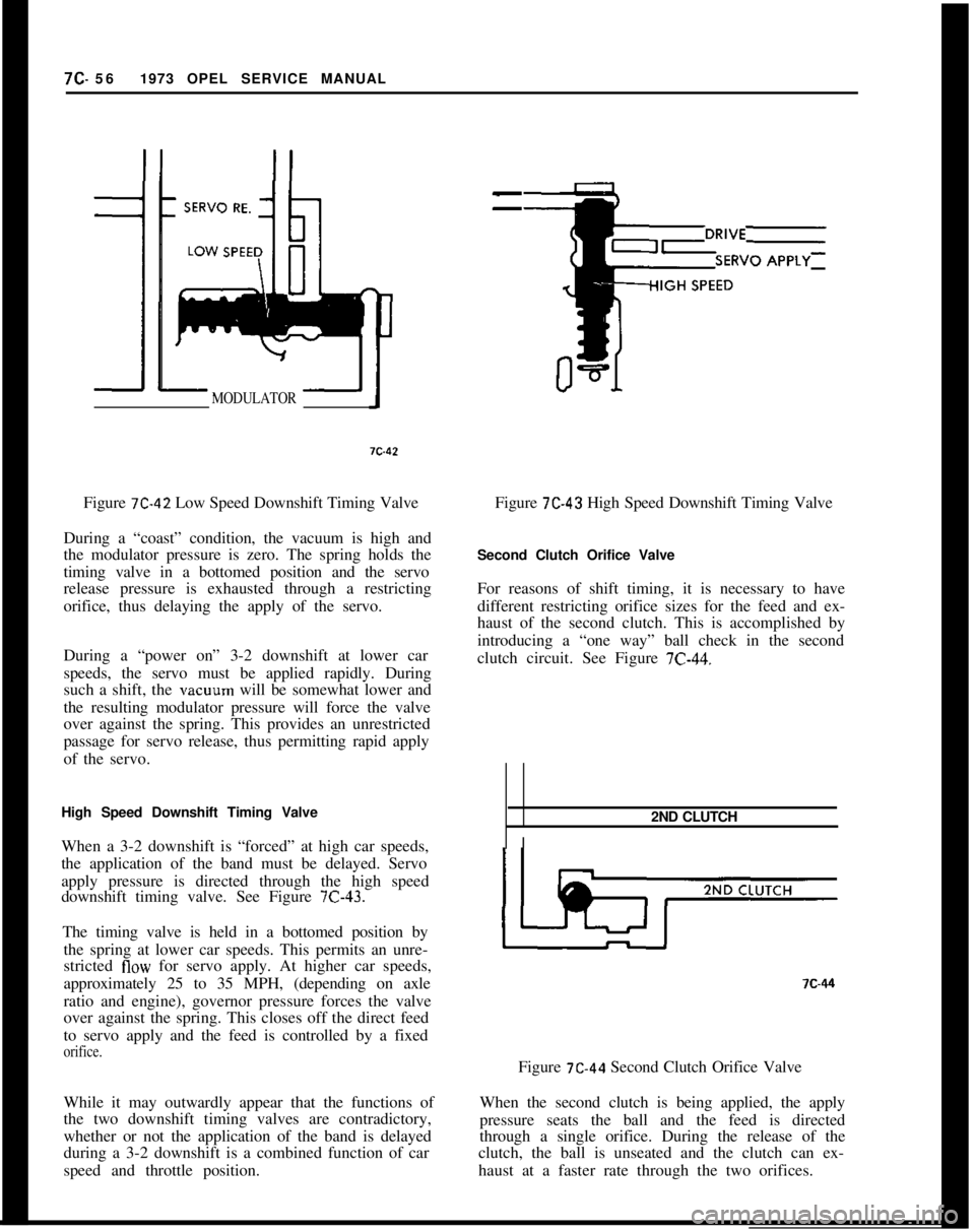
7C- 561973 OPEL SERVICE MANUALMODULATORFigure
7C-42 Low Speed Downshift Timing Valve
During a “coast” condition, the vacuum is high and
the modulator pressure is zero. The spring holds the
timing valve in a bottomed position and the servo
release pressure is exhausted through a restricting
orifice, thus delaying the apply of the servo.
During a “power on” 3-2 downshift at lower car
speeds, the servo must be applied rapidly. During
such a shift, the vacuum will be somewhat lower and
the resulting modulator pressure will force the valve
over against the spring. This provides an unrestricted
passage for servo release, thus permitting rapid apply
of the servo.
High Speed Downshift Timing Valve
When a 3-2 downshift is “forced” at high car speeds,
the application of the band must be delayed. Servo
apply pressure is directed through the high speed
downshift timing valve. See Figure
7C-43.The timing valve is held in a bottomed position by
the spring at lower car speeds. This permits an unre-
stricted
flow for servo apply. At higher car speeds,
approximately 25 to 35 MPH, (depending on axle
ratio and engine), governor pressure forces the valve
over against the spring. This closes off the direct feed
to servo apply and the feed is controlled by a fixed
orifice.While it may outwardly appear that the functions of
the two downshift timing valves are contradictory,
whether or not the application of the band is delayed
during a 3-2 downshift is a combined function of car
speed and throttle position.
--Figure
7C-43 High Speed Downshift Timing Valve
Second Clutch Orifice Valve
For reasons of shift timing, it is necessary to have
different restricting orifice sizes for the feed and ex-
haust of the second clutch. This is accomplished by
introducing a “one way” ball check in the second
clutch circuit. See Figure
7C-44.2ND CLUTCH
I?C-44
Figure
7C-44 Second Clutch Orifice Valve
When the second clutch is being applied, the apply
pressure seats the ball and the feed is directed
through a single orifice. During the release of the
clutch, the ball is unseated and the clutch can ex-
haust at a faster rate through the two orifices.
Page 419 of 625
7c. 581973 OPEL SERVICE MANUAL
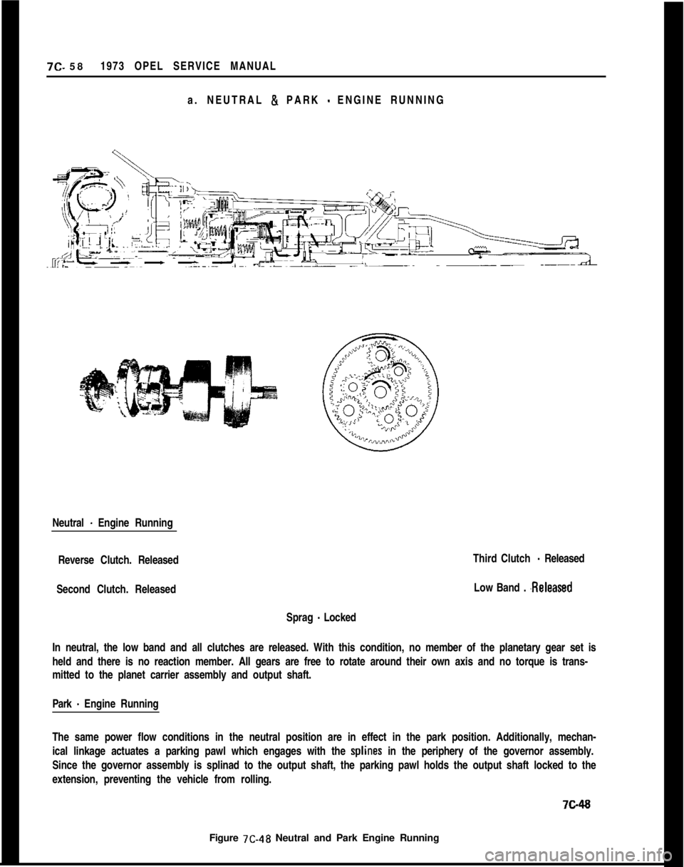
a. NEUTRAL & PARK
- ENGINE RUNNING
Neutral
- Engine Running
Reverse Clutch. Released
Second Clutch. Released
Sprag
- LockedThird Clutch
- Released
Low Band .
.ReleasedIn neutral, the low band and all clutches are released. With this condition, no member of the planetary gear set is
held and there is no reaction member. All gears are free to rotate around their own axis and no torque is trans-
mitted to the planet carrier assembly and output shaft.
Park
- Engine Running
The same power flow conditions in the neutral position are in effect in the park position. Additionally, mechan-
ical linkage actuates a parking pawl which engages with the
splines in the periphery of the governor assembly.
Since the governor assembly is splinad to the output shaft, the parking pawl holds the output shaft locked to the
extension, preventing the vehicle from rolling.7ci48
Figure 7C-48 Neutral and Park Engine Running
Page 420 of 625
AUTOMATIC TRANSMISSION7c- 59
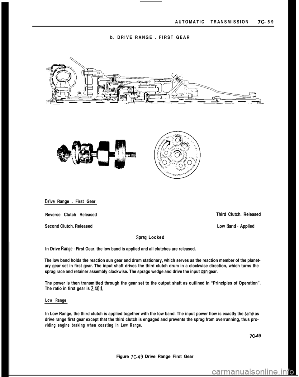
b. DRIVE RANGE . FIRST GEAROrive Range . First Gear
Reverse Clutch Released
Second Clutch. Released
Sprag Locked
In Drive Range. First Gear, the low band is applied and all clutches are released.
Figure 7C-49 Drive Range First GearThird Clutch. Released
Low Band. Applied
The low band holds the reaction sun gear and drum stationary, which serves as the reaction member of the planet-
ary gear set in first gear. The input shaft drives the third clutch drum in a clockwise direction, which turns the
sprag race and retainer assembly clockwise. The sprags wedge and drive the input
sun gear.
The power is then transmitted through the gear set to the output shaft as outlined in “Principles of Operation”.
The ratio in first gear is 2.4O:l.
Low RangeIn Low Range, the third clutch is applied together with the low band. The input power flow is exactly the
Same as
drive range first gear except that the third clutch is engaged and prevents the sprag from overrunning, thus pro-
viding engine braking when coasting in Low Range.
7c49
Page 426 of 625
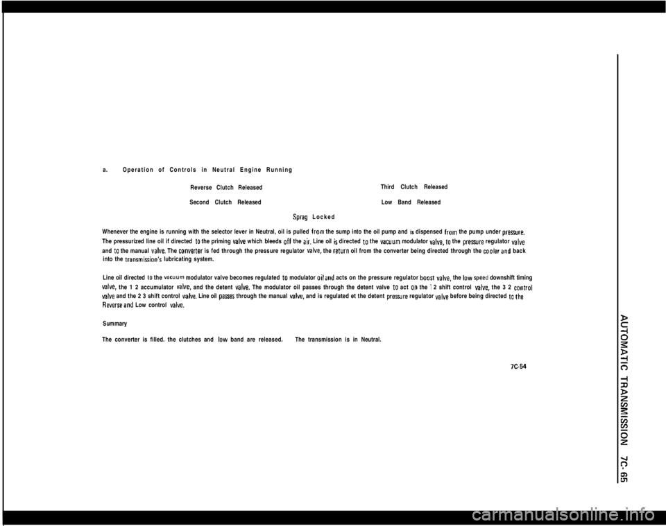
a.Operation of Controls in Neutral Engine Running
Reverse Clutch ReleasedThird Clutch Released
Second Clutch ReleasedSprag LockedLow Band Released
Whenever the engine is running with the selector lever in Neutral, oil is pulled from the sump into the oil pump and is dispensed from the pump under preure.
The pressurized line oil if directed
to the priming valve which bleeds off the air. Line oil is directed to the vacuum modulator YBIYB, to the prexwre regulator valveand
to the manual veIve. The converter is fed through the pressure regulator MIYB. the return oil from the converter being directed through the coalerand back
into the transmisGon’s lubricating system.
Line oil directed
to the vacuum modulator valve becomes regulated to modulator oiland acts on the pressure regulator boosI YBCB. the IDW speed downshift timing
valve. the 1 2 accumulator MIYB. and the detent valve. The modulator oil passes through the detent valve to act 00 the I 2 shift control give. the 3 2 control
valve and the 2 3 shift control valve. Line oil pasres through the manual v&e. and is regulated et the detent preaure regulator valve before being directed to the
Reverseand Low control delve.Summary
The converter is filled. the clutches and
IDW band are released.The transmission is in Neutral.