wheel alignment OPEL GT-R 1973 User Guide
[x] Cancel search | Manufacturer: OPEL, Model Year: 1973, Model line: GT-R, Model: OPEL GT-R 1973Pages: 625, PDF Size: 17.22 MB
Page 189 of 625
3C-22 1973 OPEL SERVICE MANUAL.
FRONT END ALIGNMENT
CONTENTS
SubjectPage No.
DESCRIPTION AND OPERATION:
FrontWheelAlignment
. . . . . . . . . . . . . . . . . . . . . . ..“...........................DIAGNOSIS: (Not Applicable)
MAINTENANCE AND ADJUSTMENTS:
Inspection Before Checking Front Wheel Alignment
AdjustingCaster
. . . . . . . . ...’ . . . . . . . . . . . . . . . . . . . . . . . . . . . . . . . . . . . . . . . . . . . . . . . . . . . . .Adjusting Camber
. . . . . . . . . . . . . . . . . . . . . . . . . . * . . . . . . . . . . . . . . . . . . . . . . . . . . . . . . . . . . .Adjusting Toe-In
. . . . . . . . . . . . . . * . . . . . . . . . . . . . . . . . . . . . . . . . . . . . . . . . . . . . . . . . . . . . . . . .King Pin Inclination
. . . . . . . . . . . . . . . . . . . . . . . . . . . . . . . . . . . . . . . . . . . . . . . . . . . . . . . . . .MAJOR REPAIR: (Not Applicable)
SPECIFICATIONS:3C-223C-223C-233C-253C-253C-26
Wheel Alignment Specifications
. . . . . . . . . . . . . . . . . . . . . . . . . . . . . . . . . .3C-26
DESCRIPTION AND OPERATIONFRONT WHEEL ALIGNMENT
Wheel alignment is the mechanics of adjusting the
position of the front wheels in order to attain the
least steering effort with a minimal amount of tire
wear.handling, but require only reasonable accuracy to
provide normal tire life. With the type of front sus-
pension used, the toe-in adjustment is much more
important than caster and camber are as far as tire
wear is concerned.
Correct alignment of the chassis is essential to proper
alignment of front and rear wheels. Briefly, the es-
sentials are that the frame must be square in plain
view within specified limits, that the top and bottom
surfaces of the front cross member must be parallel
fore and aft, and that the upper and lower control
arm must be at correct location in respect to shafts
and the front cross member. All bushings, ball joints
and bolts must be of proper torque and in usable
condition.Caster and camber adjustments need not be consid-
ered unless visual inspection shows these settings to
be out, or unless the car gives poor handling on the
road. In the majority of cases, services consisting of
inflating tires to specified pressure and interchanging
tires at recommended intervals, balancing all wheels
and tires, adjusting steering gear and setting toe-in
correctly will provide more improvement in car han-
dling and tire wear than will other front end align-
ment adjustments.
Wheel and tire balance has an important effect on
steering and tire wear. If wheels and tires are out of
balance, “shimmy” or “tramp” may develop or tires
may wear unevenly and give the erroneous impres-
sion that the wheels are not in proper alignment. For
this reason, the wheel and tire assemblies should be
known to be in proper balance before assuming that
wheels are out of alignment.The correct use of accurate front end alignment
equipment is essential to determine whether front
suspension parts have been damaged by shock or
accident, and to obtain correct alignment settings
after new parts have been installed.
MAINTENANCE AND ADJUSTMENTS
Inspection Before Checking Front Wheel AlignmentClose limits on caster, front wheel camber, andBefore making any adjustment affecting caster, cam-
theoretical king pin inclination are beneficial to carber, toe-in, theoretical king pin inclination, or
steer-
Page 190 of 625
FRONT END ALIGNMENT 3C-23
ing geometry, the following checks and inspections
must be made to insure correctness of alignment
equipment readings and alignment adjustments.
1. The front tires should have approximately the
same wear and all tires must be inflated to specified
pressures (see Wheel and Tire Specifications
- Sec-
tion 3G).
2. Check front wheel bearings for looseness and ad-
just if necessary (see Front Suspension Adjustments
- Section 3A).
3. Check for run-out of wheels and tires, (see Section
3G).
4. Check wheels and tires for balance and correct if
out-of-balance (See Section 3G).
5. Check for looseness at ball joints and tie
rdd ends;
if found excessive, it must be
corxcted before align-
ment readings will have any value.
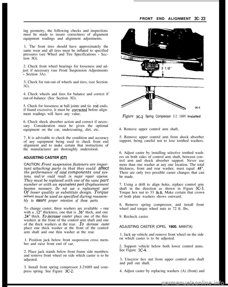
Figure SC-Z Spring Compressor J-2 1689 Installed
6. Check shock absorber action and correct if neces-
sary. Consideration must be given the optional
equipment on the car, undercoating, dirt, etc.
7. It is advisable to check the condition and accuracy
of any equipment being used to check front end
alignment and to make certain that instructions of
the manufacturer are thoroughly understood.
ADJUSTING CASTER (GT)
4. Remove upper control arm shaft,
5. Remove upper control arm from shock absorber
support, being careful not to lose toothed washers.
6. Adjust caster by installing selective toothed wash-
ers on both sides of control arm shaft, between con-
trol arm and shock absorber support. Never use
CAUTION: Front suspension fasteners are impor- more than one washer at any one location. The total
tant attaching parts in that they could
affectthickness, front and rear washer, must equal .48”.
the performance of uital components and sys-
tems, and/or could result in major repair expense.
There are only two possible caster changes that can
be made.
They must be replaced with one of the same
part
number or with an equiualentpart ifreplacement
becomes necessary. Do not use a replacement part
Of lesser quality or substitute design. Torque
values must be used as specified during reassem-
bly to mure proper retention of these parts.
7. Using a drift to align holes, replace control arm
shaft in the direction as shown in Figure
3C-3.
Torque hex nut to 33 lb.ft. Make certain that crown
of both plate washers shows outward.
To change caster, three washers are available
- one
with a
.12” thickness, one that is .36” thick, and one
.24” thick. Toincrease caster place one of the thin
washers at the front of the control arm shaft and one
of the thick washers at the rear.
To decrease caster
place one thick washer at the front of the control
arm shaft and one thin washer at the rear.
1. Position jack below front suspension cross mem-
ber and raise front end of car. 8. Remove spring compressor, and install front
wheel and torque wheel nuts to 72 ft. Ibs.
9. Recheck caster.ADJUSTING CASTER (OPEL
1900. MANTA)
2. Place jack stands below front frame side members
and remove front wheel on side which caster is to be
adjusted. 1. Jack up vehicle and remove front wheel on the side
on which caster is to be adjusted.
3. Install front spring compressor J-21689 and com-
press spring. See Figure
3C-2.
2. Support vehicle below both lower control arms.
See Figure
3C-4.
3. Unscrew hex nut from upper control arm shaft
and pull out shaft.
4. Adjust caster by replacing washers (A) (front) and
Page 192 of 625

FRONT END ALIGNMENT 3C-25
Figure 3C-6 Adjusting Toe-In (GT)ADJUSTING CAMBER
Camber is adjusted by turning the upper ball jointflange 180 degrees. This means that only two possi-
ble camber adjustments can be made. At the factory
camber is set at the smallest possible positive camber
setting for GT and smallest possible negative camber
for Opel
1900 - Manta. Rotating the flange will make
camber more positive on GT and more negative on
Opel
1900 - Manta.
1. Raise front end of car using wood block on jack
to prevent damage to front cross member.
2. Support car below lower control arm and remove
front wheel on side to be adjusted.
3. Remove ball joint from upper control arm and
front steering knuckle.
4. Lift upper control arm and turn the ball joint
flange through 180 degrees.
5. First tighten both ball joint attaching bolts on
upper control arm and then the ball stud castle nut.
Torque to 29 ft. lbs. on GT and 44
ft.lbs. on Opel
1900 - Manta. Install new cotter pin.
6. Install front wheel and torque wheel nuts to 72
lb.ft. on GT and 75 Ib.ft. on Opel 1900 - Manta.
7. Recheck camber.
ADJUSTING TOE-IN
(GT)Toe-in is adjusted by rotating the tie rod sleeves.
Refer to Figure
3C-6.1. Recheck caster and camber before proceeding
with toe-in adjustment. If correct, adjust toe-in.2. Set wormshaft and ball nut to steering gear high
point by turning steering wheel half way from one
stop to the other, noticing the following:
(a) With the steering wheel hub button removed, the
“marking” on the steering shaft end should be in a
horizontal position.
(b) The steering wheel spokes should also be in a
centered position.
3. Remove wire clamps on left and right tie rod and
push back bellows.
4. Loosen clamp bolts and tie rods. See Figure
3C-4.5. The toe-in should be
l/32” - l/8”.When adjusting toe-in, never grip tie rod on inner
ball stud joint. To avoid ball stud resting against
inside of hole in tie rod outer end, center outer end
of each tie rod to the ball stud.
6. Pull bellows over tie rods and attach with wire
clamps. The bellows must not be twisted and wire
ends must show towards steering gear adjusting
screw opening.
7. Torque clamp bolts to 12
Ib.ft.8. After toe-in adjustment, turn steering wheel sev-
eral times completely towards the left and right to
determine whether bellows are properly attached to
the tie rods and steering gear housing.
ADJUSTING TOE-IN (OPEL 1900. MANTA)
The adjustment of the toe-in has always to be carried
out on both tie rods.
Page 193 of 625
3C-26 1973 OPEL SERVICE MANUAL
1. Loosen lock nut of left and right tie rod and
slacken back nut.
2. Remove hose clamp for rubber bellows attach-
ment from respective axial joint and adjust toe-in by
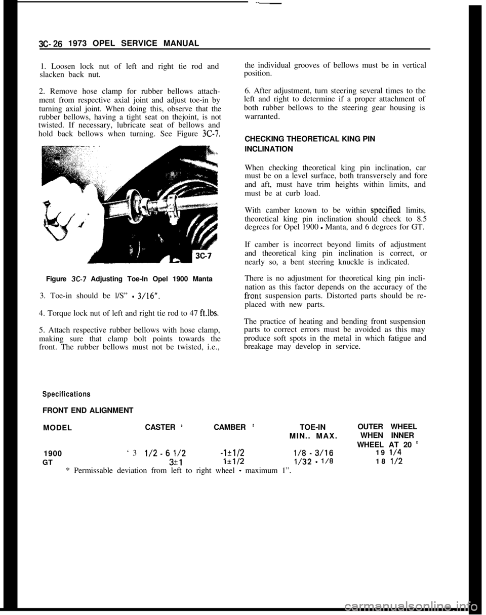
turning axial joint. When doing this, observe that the
rubber bellows, having a tight seat on thejoint, is not
twisted. If necessary, lubricate seat of bellows and
hold back bellows when turning. See Figure 3C-7.Figure
3C-7 Adjusting Toe-In Opel 1900 Manta
3. Toe-in should be l/S”
- 3/16”.
4. Torque lock nut of left and right tie rod to 47
ft.lbs.5. Attach respective rubber bellows with hose clamp,
making sure that clamp bolt points towards the
front. The rubber bellows must not be twisted, i.e.,
SpecificationsFRONT END ALIGNMENTthe individual grooves of bellows must be in vertical
position.
6. After adjustment, turn steering several times to the
left and right to determine if a proper attachment of
both rubber bellows to the steering gear housing is
warranted.
CHECKING THEORETICAL KING PIN
INCLINATION
When checking theoretical king pin inclination, car
must be on a level surface, both transversely and fore
and aft, must have trim heights within limits, and
must be at curb load.
With camber known to be within specitied limits,
theoretical king pin inclination should check to 8.5
degrees for Opel 1900
- Manta, and 6 degrees for GT.
If camber is incorrect beyond limits of adjustment
and theoretical king pin inclination is correct, or
nearly so, a bent steering knuckle is indicated.
There is no adjustment for theoretical king pin incli-
nation as this factor depends on the accuracy of the
fronts suspension parts. Distorted parts should be re-
placed with new parts.
The practice of heating and bending front suspension
parts to correct errors must be avoided as this may
produce soft spots in the metal in which fatigue and
breakage may develop in service.
MODELCASTER
’CAMBER ’TOE-INOUTER WHEEL
MIN.. MAX.WHEN INNER
WHEEL AT 20
’1900‘3
l/2-61/2-1?1/2I/% - 3/1619 l/4GT3+1
1+1/2l/32 - l/818 l/2* Permissable deviation from left to right wheel
- maximum 1”.
Page 225 of 625
3G- 581873 OPEL SERVICE MANUALTire Wear IrregularitiesAn additional cause of vibrations may sometimes be
tire wear irregularities. These can also produce noise
disturbances, and can be generally corrected by
rotating the tires, Figure
3G-6. Before proceeding
further, locate and correct the cause of the irregular
tire wear. See Figure
3G-7.Use the criss-cross method of rotation of tires only
when all four tires are equally worn. In some in-
stances, it may be necessary to put the truest running
assemblies (those with the lowest tolerances) on the
front of the car.
Wheel Nut Torque end Tightening SpecificationsDuring all wheel installations, it is important to use
the correct procedures for installing wheel nuts and
torquing them uniformly and in proper sequence.
This is important in order to avoid possible distor-
tion of the brake drum or disc, and to minimize
damage to lug and nut threads and wheel stud holes.
To assure uniform tightening of wheel lug nuts, the
following procedure is recommended:
1. Install wheel lug nuts in a criss-cross pattern and
tighten just enough to seat wheel against hub. This
assures proper piloting of the wheel on its hub.
2. Tighten lug nuts uniformly to proper torque of 65
Ib.ft. using criss-cross pattern.
An impact wrench should not be used, as uniform
torque control cannot be maintained.
Summary of Diagnosis end Correction of Tire and
Wheel Vibration1. Inflate all tires to recommended pressure and
road-test car with owner to define problem.
2. Spin front tire/wheel assemblies with wheel driv-
ing equipment. Rear wheels may be spun with tires
off the ground and with one wheel held at a time. The
offending tire may cause vibration that may be felt
by touching the bumper or fender. By process of
elimination, determine offending tire/wheel assem-
bly.
3. Check for tire/wheel unbalance. Balance, if neces-
sary.4. Check each tire/wheel assembly on the car for
radial runout on the tire tread. Wheel and tire assem-
blies exceeding
.050 inches may be considered as
offending assemblies. Offending tire/wheel assemblyshould be deflated and the tire repositioned (indexed)
180 degrees from original location.
5. After repositioning, rebalance tire/wheel assembly
(static and dynamic preferred).
6. Test drive and evaluate correction.
The following procedure should be used to determine
cause of roughness or vibration with car in operation
at various speeds:
I. Jack up all wheels having jack support rear end of
car at center of rear axle housing.
2. With transmission in “Drive”, run engine at vari-
ous car speeds to note speeds at which vibration or
roughness occurs.
3. Remove rear wheels and run engine again at the
critical speeds noted in step 2. If roughness is gone,
the condition is caused by unbalanced wheel and tire
assemblies.
4. If roughness still exists with rear wheels removed,
remove rear brake drums and repeat the running
test. Elimination of the roughness indicates out of
balance brake drums.
5. If roughness still exists with brake drums
removed, run engine with transmission in “Neutral”.
Elimination of the roughness indicates that propeller
shaft is out of balance. Continued roughness indi-
cates an out-of- balance engine.
ABNORMAL TIRE WEAR
General Operating ConditionsAssuming that there is no misalignment condition to
cause abnormal wear, the life of tires depends largely
upon car operation conditions and driving habits.
Tires wear at a much faster rate in some localities
than in others because of road and operating condi-
tions. Some types of roads are much more abrasive
than others. Tire wear is also dependent upon the
number of hills and mountains which the car must
go up and down, the severity of grades, the number
of starts and stops, driging speeds, the amount of rain
and snow, and prevailing temperatures. Tire
wear
increases rapidly with speed, temperature, and loadon tire. Tires used at low speeds, in cool climates, or
with light loads will have longer life than tires used
for high-speed driving in hot climates with heavy
loads.
Driving habits have a very important hearing on tire
life. A careful driver may obtain much greater mile-
age from a set of tires than would be obtained by a
Page 228 of 625
WHEELS AND TIRES3G- 61Cornering Tread WearThe modern independently-sprung automobile al-
lows the driver to negotiate turns at a high rate of
speed with a greater feeling of safety. This fact is
responsible for a comparatively new type of tread
wear that can easily be mistaken for toe or camber
wear.When a car is making a turn, the tires are supposed
to be rolling in a circle. When the turn is made at
high speed, however, centrifugal force acting on the
car causes the tires to be distorted sideways and to
slip or skid on the road surface. This produces a
diagonal cross type of wear, which in severe cases
will result in a fine or sharp edge on each rib of the
tire treads.
Cornering wear can be distinguished from toe or
camber wear by the rounding of the outside shoulder
of the tire and by the roughening of tread surface in
this section denoting severe abrasion. See Figure
3G-7.No alignment or tire pressure cahnge can be made
that will relieve cornering wear. Only the driver can
effect a cure and that is by slowing down on curves.
Heel and Toe Tread WearHeel and toe wear is a saw-tooth effect with one end
of each tread block worn more than the other.
The end which wears is the one that first grips the
road when the brakes are applied. High-speed driv-
ing and excessive “se of the brakes will cause this
type of irregular tire wear. This type of wear will
occur on any type of block tread design. See Figure3G-7.
Heel and toe wear is not so prevalent on the rear tires
because of the propelling action which creates a
counteracting force which wears the opposite end of
the tread block. These two stresses on the rear tires
wear the tread blocks in opposite directions and re-
sult in more even wear while on the front tires, the
braking stress is the only one which is effective. This
may be counteracted by interchanging tires.
A small amount of irregular wear, slightly
saw-toothed in appearance, at the outer segments of tires
is a normal condition and is due to the difference in
circumference between the center and the outer
edges of the tire tread. This saw-toothed appearance,
however, will be exaggerated by underinflation, im-
proper toe-in, or both.Cupped or Scalloped Type Tire Wear
Cupping or scalloping is associated with wear on acar driven mostly at highway speeds without recom-
mended tire rotation. Factors which promote cup-
ping include underinflation, incorrect toe-in setting
or camber setting, and steady highway speeds on
smooth, paved surfaces as opposed to gravel or
rough asphalt.
The following recommendations suggest action that
may be taken to help prevent cupping.
1. Rotate tires as recommended in Figure
3G-6.2. Frequently inspect front tires for irregular wear
due to underinflation, improper toe-in setting, or
camber setting. Regardless of the original cause of
cupped tread wear on either front tire, no alignment
or balance job, however perfect, can prevent future
excessive wear of the spots. Once a front tire acquires
flat or cupped spots, additional wear will continue at
a rapid rate. At the time of correction, however, the
cupped tire should be interchanged with a rear tire
on which the tread runs true. The cupped tire will,
to a certain degree, true itself on a rear wheel.
Although not normally the cause of cupping, the
following factors can contribute to the problem.
Looseness of parts in the suspension system, such as
worn steering knuckle ball joints, loose wheel bear-
ings, inoperative shock absorbers, and any excessive
looseness throughout the steering system all tend to
allow the front wheels to kick around and, if any of
the wheel alignment factors are incorrect, irregular
spotty tire tread wear of one type or another may
result.
Wobble or runout of a tire, either front or rear, due
to bent wheel or to tire being improperly mounted
will cause uneven wear.
MAINTENANCE AND ADJUSTMENTSDEMOUNTING AND MOUNTING
TUBELESS TIRESDue to “se of symmetrical rims, tires must be
mounted over the narrow rim shoulder i.e., over out-
side rim flange.
When demounting a tubeless tire “se care to avoid
damaging the rim-seal ridges on tire beads DO NOT
USE TIRE IRONS TO FORCE BEADS A WA Y
FROM WHEEL RIM FLANGES.
When tire is removed, inspect it carefully to deter-
mine whether loss of air was caused by puncture or
by improper
tit of beads against rim flanges. If im-
proper fit is indicated, check wheel as follows: Do
not reuse dented rims.
Page 315 of 625
6A- 24 1973 OPEL SERVICE: MANUAL
on front side of timing chain to permit reinstallation
in original position.
Timing Chain Cover and Timing
Chain installation
Reinstall timing chain cover by reversing removal
procedures, pay particular attention to the following
points.
1. Clean all parts, check for wear and replace as
required. The Parts Department supplies either the two sprockets complete with chain or the chain
alone. It is not permissible to replace sprockets alone.
The chain tensioner is, with the, exception of the
tensioner body, only available as a complete unit.
2. Turn crankshaft so that key for sprocket is on top
and vertical. Assemble chain’, with camshaft
sprocket, then put chain on crankshaft sprocket al-
ready installed. Be sure paint dot
on chain is in front
so that chain moves in same direction as prior to
disassembly.
3. Make sure camshaft sprocket mark is in alignment
with mark on support and chain in parallel with
damper block.
4. To install new timing case oil seal, drive out oil
seal from the rear using a drift. Coat circumference
of oil seal sparingly with suitable sealer and press seal
in, using tool J-22924. Take care not to damage tim-
ing case. See Figure
6A-40. 5. Inspect chain tensioner for proper operation and
reusability.
6. Install timing case rubber gaskets to cylinder
block. Stick on with grease as necessary. Gaskets will
somewhat overlap with oil pan gasket.
7. Position timing cover onto guide pin in upper left
corner of cylinder block and insert centering bolt
through timing chain cover into lower right corner
of cylinder block. See Figure
6A-40A. No sealing is
required.
SA-40.4
Figure 6A-40A Installing Timing Chain Cover
INSTALLER
Figure 6A-40 Installing Timing Cover Oil Seal onProtector
It is not necessary to use crankshaft bolt to install
seal when cover is off engine. 8. Install cylinder head
After sprocket has been attached to camshaft, re-
check alignment
LO see that chain has not slipped. At
this time both No.
1 and No. 4 pistons will be at TDC
position. No. 4 piston will be in tiring position and
No. 1 piston up on exhaust stroke. To time engine to
fire on No. 1 cylinder, rotate crankshaft 360 degrees.
This will position the timing mark 180 degrees from
original alignment of camshaft sprocket and support
bracket, and will completely close No. 1 intake and
exhaust valves. Also, the timing mark on the fly-
wheel
(ball) and cylinder block (pointer) will coin-
cide. See Figure
6A-41.
Replacing Timing Cover Oil Seal
(Engine Installed)
1. Remove fan belts.
2. Remove crankshaft pulley bolt and remove pulley. 3. Insert screwdriver behind seal and rest screw-
driver on crankshaft pin. Pry out oil seal.
Page 367 of 625
7A- 61973 OPEL SERVICE MANUAL1. FIywheeI and Pressure PlateExamine friction surfaces of flywheel and pressure
plate for scoring or roughness. Slight roughness may
be smoothed with fine emery cloth, but if surface is
deeply scored or grooved the part should be re-
placed.
2.
CJutch Driven Plate
Inspect driven plate for condition of facings, loose
rivets, broken or very loose torsional springs.
If facings are worn down near rivets or are oily, the
plate assembly should be replaced. A very slight
amount of oil on clutch facings will cause clutch grab
and chatter. A large amount of oil on facings will
cause slippage. Removal of oil by solvents or by buff-
ing is not practical since oil will continue to bleed
from facing material when hot.
When oil is found on driven plate facings, examine
transmission drainback hole, pilot bushing, engine
rear main bearing and other points of possible oil
leakage.
Test the fit of driven plate hub on transmission main
drive gear for an easy sliding fit.
Regardless of whether the old plate or a new one is
to be installed, the plate should be checked for run-
out. Lateral run-out measured at disc circumference
should not exceed
.016 inch.
Inspect clutch release bearing for scoring or exces-
sive wear on front contact face. Test for roughness of
balls and races by pressing and turning front race
slowly. Inspect main drive gear pilot bushing in
crankshaft. If bushing is rough or worn it should be
Figure JA-3replaced. If replacement is necessary, remove bear-
ing with Tool J-21718 and Slide Hammer J-7004-1.
Install new bearing using J-21706. See Figure 7A-3
for removal procedure and Figure 7A-4 for installa-
tion.
\,,
Figure JA-4
Installation of Clutch1. Index alignment marks on clutch assembly and
flywheel. Place driven plate on pressure plate with
long end of splined hub facing forward toward the
flywheel. See Figure 7A-5.
2. Insert alignment Tool J-22934 through clutch
cover and driven plate.
3. Hold complete assembly against flywheel while
inserting end of Tool J-22934 into pilot bearing in
crankshaft.
4. Index the alignment marks and install four (4)
clutch cover to flywheel bolts finger tight. Complete
torquing bolts alternately and evenly one at a time.
5. Torque attaching bolts to 36 lb.ft. and remove
alignment tool.
6. Install release bearing.
7. Install flywheel housing and torque lower bolts to
36
lb.ft.8. Install flywheel housing lower cover.
9. Install clutch return spring and control cable.
10. Install transmission. See Manual Transmission
Section for procedure.
11. Adjust clutch control cable. Refer to paragraph7A-3.
Page 621 of 625
SubjectPage Number
Subject Page Number
A
Air Conditioning Refrigerant Components .................
98.17
Opel 1900
& Manta-In Car Components .....9B-90
GT.ln Car Components..................98-97
Alignment Opel 1900
& Manta .....................3C-22
GT-Opel ..............................
3C-22
Alternator Description ...........................
lD-28
Specifications. .........................1 D-35
Overhaul K-l..........................lD-30
Removal & Installation ..................lD-30
Testing...............................lD-29
Wiring Diagrams
Manta .............................
1 J-105
Opel 1900
..........................lJ-103
GT ................................
lJ-107
AM
Radio-GT............................9C-105
AM Radio-Opel 1900 &Manta ...............
9C-109
Antenna, Installation .......................
9C-111
Antenna Trimmer .........................
9C-110
Assembly of Transmission from Major Units Manual ...............................
78-23
3 Speed Automatic .....................
7C-103
Axle,
R&r, Disassembly ....................48~11
Bolt Torque Specifications
Engine ...............................
6A-27
Transmission. Manual ....................
78-33
3 Speed Automatic .....................
7C-136
Clutch ...............................
7A-7
Body ................................
2A-4
Brakes
Brake Drum, Shoes & Linings .............5C-28
Hydraulic Wheel Cylinder ................
5C-30
Hydraulic Master Cylinder ................
5A-2
Parking Brake Cables .....................
5C-33
Standard Brakes ........................
X-22
Disc Brakes...........................5B-10
Brake Booster and Vacuum
Coritrol Valve ....5A-5
Bumpers, Front and Rear ...................
ZH-33
C
B
Balance,,Wheel and Tire....................3G-62
Ball
J&tUpper .........................3A-7
Lower ...............................
3A-7
Battery
Specifications ..........................
lA-9
Testing...............................lA-6
Charging ..............................lA-9
Trouble Diagnosis ......................lA-4
Battery Test 421.........................l A-6
Belt Tensions ............................
68.33
Blower and Air Inlet Assembly, Removal and Installation
Owl 1900&Manta.....................9A-15
GT
.: ................................9A-5
Body Name Plate ............................
OA-1
Style’Numbers ......................... OA-2
Windows and Weatherstrips ...............
ZC-9
Doors ................................
ZD-13
Interior Trim and Headlining ..............
26-33
Seatsi................................26-33
Roof&d Sunroof-Opel 1900
& Manta ......2F.24 Camshaft,
1.9L
Engine .....................6A-25
Car Model Identification .......
.,............OA-1
Carburetor..............................6E-44
Trouble Diagnosis ......................
6E-49
Description ...........................
6E-44
Overhaul .............................
6E-53
Adjust ...............................
6E-50
Removal
& Installation ......,............6E-52
Specifications ..........................
6E-58
Charging
System
Description ..............
:............ 1 D-28
Specifications. ............
.,............lD-35
Testing..................:............lD-29
Wiring Diagrams
Manta .............................
lJ-105
Opel 1900 ..........................
lJ.103
GT ................................
lJ-107
Chart Lubrication ........................ OC-5
Chassis Springs, Front. ........
!............3A-15
Clutch, Second-Automatic Transmission .......
7C-103
Clutch Adjustment .........................
7A-4
Control Arm Front Upper ...................
:............3A-10
Lower ...............................
3A-11
Converter Checking Procedure ................
7C-125
Coolant Flow ............................
68-32
4 Speed Manual Transmission ...
!,...........7B-12
Cranking System. See Starting
SyStem
Crankshaft..............................6A-16
Cylinder Head ...............
:............6A-12
D
Description
3.Speed Automatic.....................7C-37
Page 622 of 625

Subject
Page NumbelSubjectPage Number4.Speed Manual I..
Clutch
Detent Cable Adjustment
:Differential
Directional Signal Switch
Repair Opel 1900 & Manta
Repair GT
:Disassembly of
4.Speed Manual Transmission
DistributorFunction of Valves and Hydraulic Control Units
Opel
3.Speed Automatic.................
74-21
Fuse Chart..............................lG-56
Fusible Link.............................
lA-8Specifications.
Point Replacement..
..,78-127A-
17c-9148-73E-393E-4878.23
1C-26
1 c-20
GEGas Tank See Fuel Tank
General Specifications
Engine...............................6A-28
Opel 3.Speed Automatic
.................7C-134
Transmission, Manual.,
..................78-33
Clutch...............................7A-7
Body................................ZA-4
Governor Drive Gear
Opel
3.Speed Automatic.................7C-103
Grille
Opel 1900 & Manta.....................8A-7
GT..................................8A-6 Electrically Heated Rear Window
Engine
General Description
Cooling System
Lubrication System
Trouble Diagnosis
Exhaust Manifold
Exhaust System
Removal and Installation
External Oil Leaks,
Opel 3 Speed Automatic
FFast Idle Adjustment
..................
Filter-Engine Oil
......................
Fluid Checking Procedure Transmission
Opel 3Speed Automatic.............
Frame-Opel 1900 & Manta.............
Frame
GT-Opel......................
SWVOOpel Xipeed Automatic...........
Front Suspension
Opel1900&Manta.................
GT..............................
Front Wheel Alignment................
Front Wheel Bearing Adjustment
All Series.........................
Fuel Gauge
Trouble Diagnosis
Opell$OO&Manta...............
GT............................
Fuel Pump Operation..................
Fuel System
Fuel Tank (Opel 1900 & Manta)
.......
Fuel Lines (Opel 1900 & Manta)
.......
Fuel Tank
(GT)....................
Fuel Gauge Tank Unit
(GT)...........
Fuel Lines
(GT)....................
Fuel Tank Removal and Installation....
Cleaning Tank.....................
lH-576A-268-326A-46A-66A-126D-427C-816E-51
oc-77C~Bl2B-826-77c-1003A-23A-23C-223A-4
HHazard Warning Flasher
....................lG-55
Headlamp Aiming
.........................1 F-46
Headlamp Switch
Opel 190.0 & Manta
.....................1 F-46
Headlamp Mechanism GT
..................8A-2
Heater System Opel 1900 &Manta
Trouble Diagnosis
......................9A-11
Description and Operation
................9A-10
Adjustments and Minor Service............9A-12
Removal and Installation
.................9A-12
Specifications..........................$A-16
Heater System GT
Trouble Diagnosis
......................9A-4
Description and Operation
................9A-2
Adjustments and Minor Service
............9A-4
Removal and Installation.................9A-5
Specifications..........................$A-9Horn
Operation.............................lG-54
Hydraulic Operation
Opel
3.Speed Automatic.................7C-64
IIdentification Number Vehicle...............
OA-1ldle.Adjustment
..........................6E-51
Inflation Pressures, Tires.
...................36-62
Ignition Coil
Specifications.
.........................
lC-26Identification, Engine
......................
OA-1Ignition System
Timing...............................
lC-20Instrument Panel Parts Removal