torque OPEL GT-R 1973 Workshop Manual
[x] Cancel search | Manufacturer: OPEL, Model Year: 1973, Model line: GT-R, Model: OPEL GT-R 1973Pages: 625, PDF Size: 17.22 MB
Page 233 of 625
4A- 21973 OPEL SERVICE MANUAL
PROPELLER SHAFT AND CENTRAL JOINT
CONTENTS
Subject
DESCRIPTION AND OPERATION:
PropellerShaftandCentralJoint. . . . . . . . . . . . . . . . . . . . . . . . . . . . . . . .DIAGNOSIS: (Not Applicable)
MAINTENANCE AND ADJUSTMENTS: (Not
Applicable)
MAJOR REPAIR:
’Propeller Shaft Removal andInstallation
. . . . . . . ..-....Disassembly andAssembly of CentralJoint
. . . . . . . . . . . .SPECIFICATIONS:
Propeller Shaft and Central Joint Specifications . .
DESCRIPTION AND OPEqATlON
PROPELLER SHAFT AND CENTRAL JOINTDue to the use of both automatic and manual trans-
missions, propeller shafts of various lengths are re-
quired depending upon vehicle, engine, and
transmission (manual or automatic) application. The
propeller shaft is of a strong design due to increased
engine torque. It is also a one piece tubular shaft, but
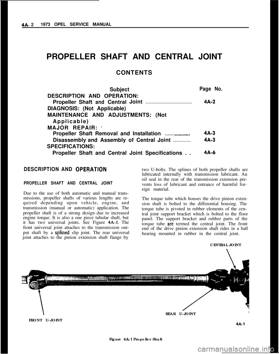
it has two universal joints. See Figure 4A-1. The
front universal joint attaches to the transmission out-
put shaft by a splined slip joint. The rear universal
joint attaches to the pinion extension shaft flange by
Page No.
4A-2
4A-3
4A-3
4A-6two U-bolts. The splines of both propeller shafts are
lubricated internally with transmission lubricant. An
oil seal in the rear of the transmission extension pre-
vents loss of lubricant and entrance of harmful for-
eign material.
The torque tube which houses the drive pinion exten-
sion shaft is bolted to the differential housing. The
torque tube is pivoted in rubber elements of the cen-
tral joint support bracket which is bolted to the floor
panel. The support bracket and rubber parts of the
torque tube
arc termed the central joint. The front
end of the drive pinion extension shaft rides in a ball
bearing mounted in rubber in the central joint.
CENTRAL JOINT\REAR U-JOINT
FRONT U-JOINT
4A-1Figure 4R1 Propeller Shaft
Page 234 of 625
PROPELLER SHAFT AND CENTRAL JOINT4A- 3MAJOR REPAIR
PROPELLER SHAFT REMOVAL AND
INSTALLATION
Removal
1. Raise rear of car and support on jack stands at rear
jack brackets.
2. Disconnect parking brake cable equalizer from
rod.3. On the Opel
1900 and Manta, unhook parking
brake cable from floor panel.
4. On the Opel 1900 and Manta, unhook exhaust
system and let it down.
5. Mark the mating parts of the U-joint and the drive
pinion extension shaft flange.
6. Loosen bolt locks and remove bolts or nuts.
7. Work propeller shaft slightly forward, lower rear
end of shaft and slide assembly rearward. Remove
thrust spring from front of propeller shaft.
S. Install plug in transmission extension housing to
prevent loss of lubricant.
installation
CAUTION:
Fasteners in the foJlowing steps are impor-
tant attaching parts in that they could affect the
performance of
vital components and systems, and-
/or could
result in major repair expense. They must
be replaced with one of the
samepart number or with
an equivalent part
ifreplacement becomes oecessary.
Do not use a replacement part of lesser quality or
substitute design. Torque values must be used as
specirid during reassembly to assure proper reten-
tion of these parts.1. Remove plug from rear of transmission.
2. Slide thrust spring onto transmission output shaft
and slide propeller shaft through the oil seal and onto
the transmission output shaft. Make certain trans-
mission rear seal is not damaged.
3. Align rear universal joint and pinion flange locat-
ing marks and secure with respective bolts and lock
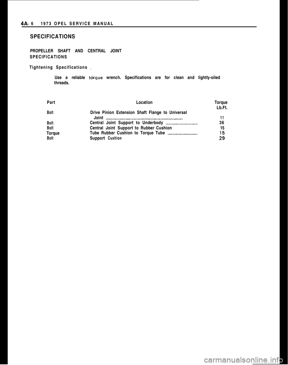
plates. Torque bolts to 11
lb.ft. Bend lock plate tangs
to secure bolts or nuts.
4. Connect parking brake cable equalizer to brake
rod and adjust to specifications.
5. On the Opel 1900 and Manta connect parking
brake cable to floor panel.DISASSEMBLY AND ASSEMBLY OF THE
CENTRAL JOINT
Disassembly of Central Joint1. Raise and support rear of car under axle tubes.
2. Release brake line bracket from rear of torque
tube.3. Disconnect parking brake cable equalizer and re-
turn spring from brake rod.
4. On the Opel 1900 and Manta, unhook exhaust
system and let it down.
5. Mark universal joint and flange. Disconnect pro-
peller shaft from flange and support it out of the way.
6. Support torque tube with floor jack using mini-
mum pressure.
7. Remove the central joint bracket to underbody
attaching bolts.
8. Allow floor jack to lower the torque tube.
9. Disconnect torque tube from differential carrier by
removing the attaching bolts.
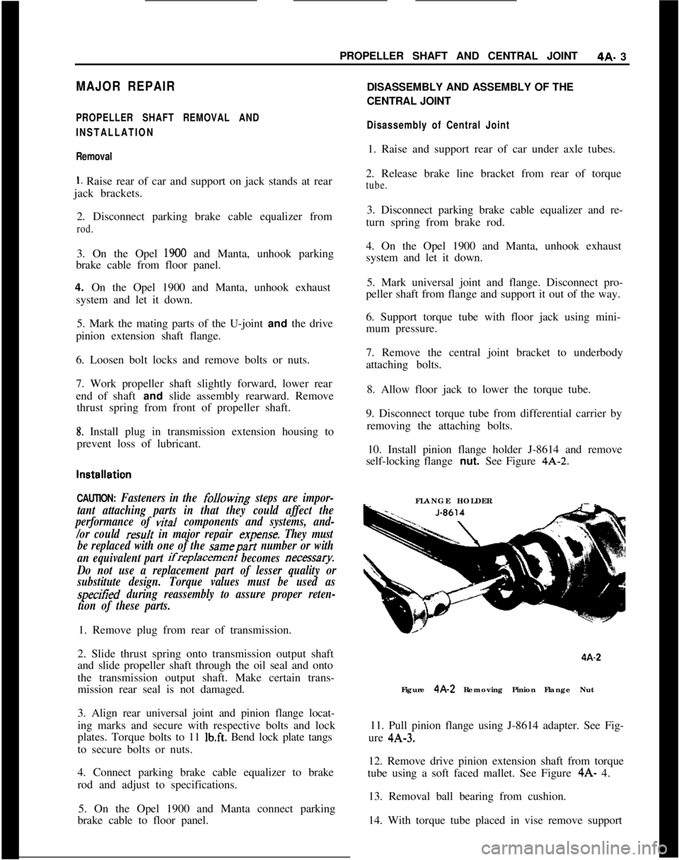
10. Install pinion flange holder J-8614 and remove
self-locking flange nut. See Figure 4A-2.
FLANGE HOLDER4A-2
Figure 4A-2 Removing Pinion Flange Nut
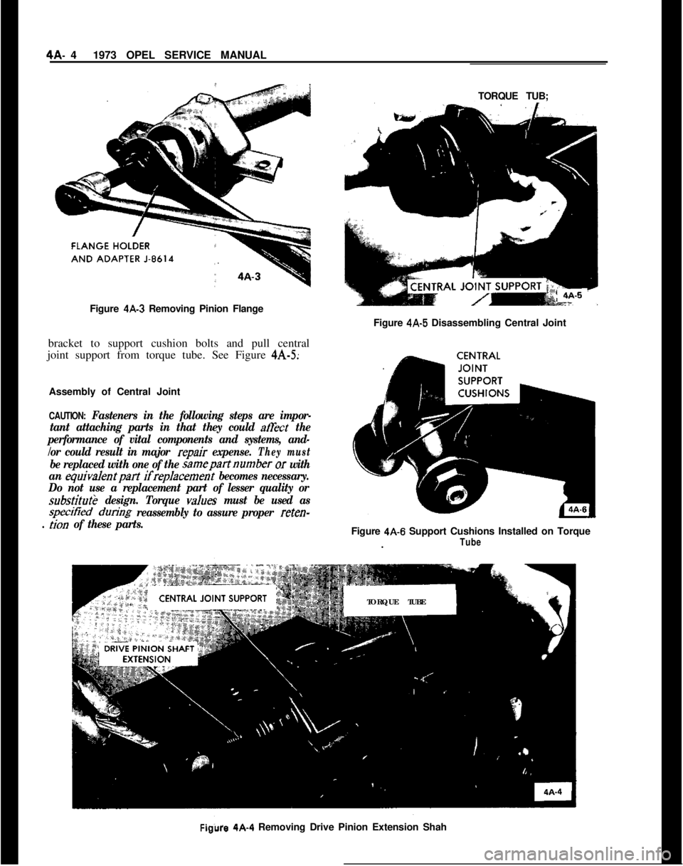
11. Pull pinion flange using J-8614 adapter. See Fig-
ure 4A-3.
12. Remove drive pinion extension shaft from torque
tube using a soft faced mallet. See Figure 4A- 4.
13. Removal ball bearing from cushion.
14. With torque tube placed in vise remove support
Page 235 of 625
4A- 41973 OPEL SERVICE MANUAL
Figure 4A-3 Removing Pinion Flange
bracket to support cushion bolts and pull central
joint support from torque tube. See Figure 4A-5;
Assembly of Central Joint
CAUTION: Fasteners in the following steps are impor-
tant attaching parts in that they could
ah&t the
performance of vital components and systems, and-
/or could result in major
repair expense.They must
be replaced with one of the samepartnumber or with
an
equivalentpart ifreplacement becomes necessary.
Do not use a replacement part of lesser quality or
substitutk design. Torque vah~es must be used as
specitied dun’ng reassembly to assure proper reten-
. lion of these parts.TORQUE TUB;
Figure
4A-5 Disassembling Central Joint
Figure
4A-6 Support Cushions Installed on Torque
.TubeTORQUE TUBE
Figure 4A-4 Removing Drive Pinion Extension Shah
Page 236 of 625
PROPELLER SHAFT AND CENTRAL JOINT4A- 5
1. Check condition of support cushions. If new cush-
ions are installed, torque to 29 lb. ft. See Figure 4A-6.
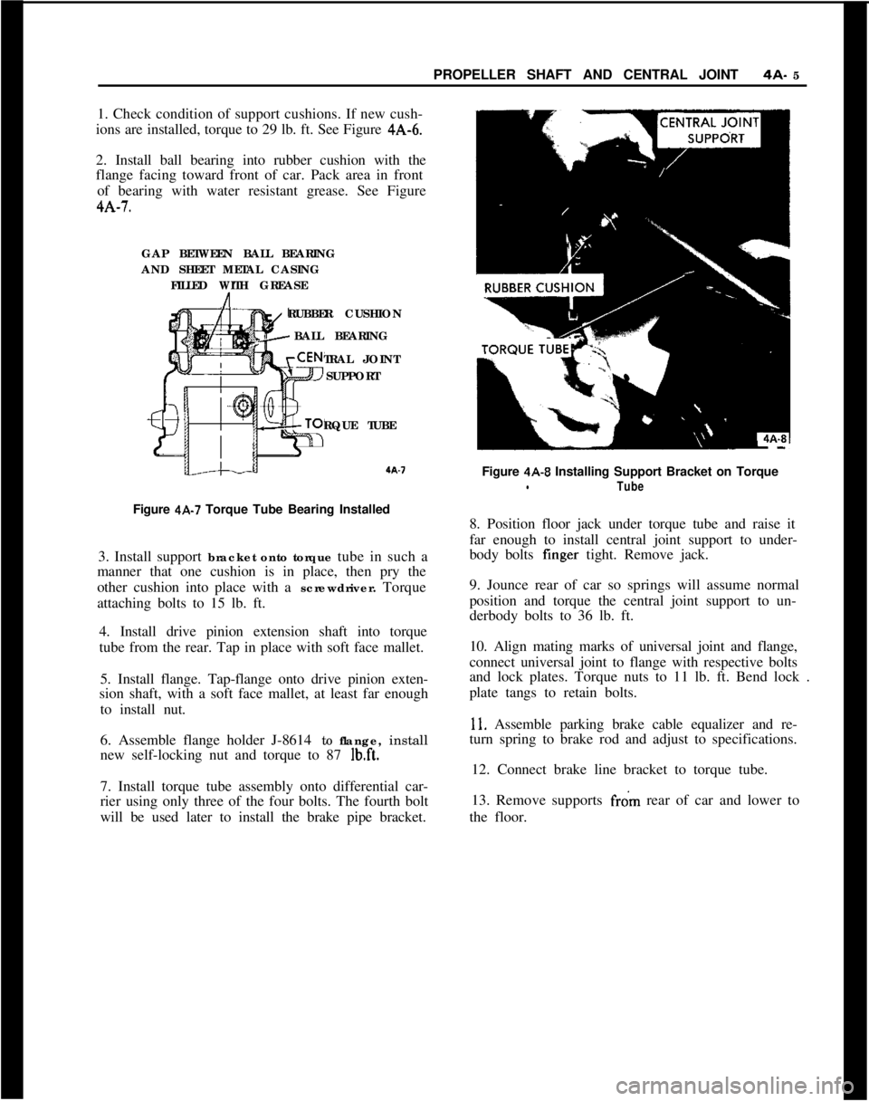
2. Install ball bearing into rubber cushion with the
flange facing toward front of car. Pack area in front
of bearing with water resistant grease. See Figure4A-7.
GAP BETWEEN BALL BEARING
AND SHEET METAL CASING
FILLED WITH GREASE
RUBBER CUSHION
BALL BEARING
TRAL JOINT
SUPPORT
RQUE TUBEa.7
Figure 4A-7 Torque Tube Bearing Installed
3. Install support bracket onto torque tube in such a
manner that one cushion is in place, then pry the
other cushion into place with a screwdriver. Torque
attaching bolts to 15 lb. ft.
4. Install drive pinion extension shaft into torque
tube from the rear. Tap in place with soft face mallet.
5. Install flange. Tap-flange onto drive pinion exten-
sion shaft, with a soft face mallet, at least far enough
to install nut.
6. Assemble flange holder J-8614 to flange, install
new self-locking nut and torque to 87
lb.ft.7. Install torque tube assembly onto differential car-
rier using only three of the four bolts. The fourth bolt
will be used later to install the brake pipe bracket.Figure
4A-8 Installing Support Bracket on TorquelTube8. Position floor jack under torque tube and raise it
far enough to install central joint support to under-
body bolts finger tight. Remove jack.
9. Jounce rear of car so springs will assume normal
position and torque the central joint support to un-
derbody bolts to 36 lb. ft.
10. Align mating marks of universal joint and flange,
connect universal joint to flange with respective bolts
and lock plates. Torque nuts to 11 lb. ft. Bend lock .
plate tangs to retain bolts.
11. Assemble parking brake cable equalizer and re-
turn spring to brake rod and adjust to specifications.
12. Connect brake line bracket to torque tube.
13. Remove supports
f&n rear of car and lower to
the floor.
Page 237 of 625
4A- 61973 OPEL SERVICE MANUAL
SPECIFICATIONSPROPELLER SHAFT AND CENTRAL JOINT
SPECIFICATIONS
Tightening Specifications ~
Use a reliable to’rque wrench. Specifications are for clean and lightly-oiled
threads.
Part
Bolt
Bolt
BoltTorque
BoltLocation
Drive Pinion Extension Shaft Flange to Universal
Joint
.._.....................................................................Central Joint Support to Underbody
_.._....._........._..........CentralJointSupport toRubber Cushion
Tube Rubber Cushion to Torque Tube
._.........._...............Support
CushionTorque
Lb.Ft.
1136
15
Page 241 of 625
4B- 101973 OPEL SERVICE MANUAL
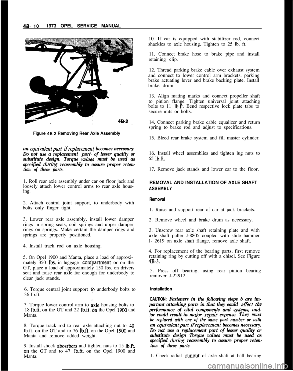
Figure 48-Z Removing Rear Axle Assemblyan equiva/entpart ifreplacement becomes necessary.
Do not use a replacement
part of lesser quality or
substitute design. Torque
values must be used as
specified
during reassembly to assure proper reten-
tion of these parts.1. Roll rear axle assembly under car on floor jack and
loosely attach lower control arms to rear axle hous-
ing.
2. Attach central joint support, to underbody with
bolts only finger tight.
3. Lower rear axle assembly, install lower damper
rings in spring seats, coil springs and upper damper
rings on springs. Make certain the damper rings and
springs are properly positioned.
4. Install track rod on axle housing.
5. On Opel 1900 and Manta, place a load of approxi-
mately 350
Ibs. in luggage conipartment or on the
GT, place a load of approximately 150 lbs. on drivers
seat and raise rear axle far enough for underbody to
clear jack stands.
6. Torque central joint support t$ underbody bolts to
36 lb.ft.
7. Torque lower control arm to
Axle housing bolts to
18
Ib.ft. on the GT and 22 lb.ft. dn the Opel 1900 and
Manta.
8. Torque track rod to rear axle attaching nut to
40lb.ft. on the GT and to 76
lb.ft. on the Opel 1900 and
Manta and remove added weight.
9. Install shock abosrbers and tighten nuts to 15
Ib.ft.on the GT and to 47
Ib.ft. on the Opel 1900 and
Manta.10. If car is equipped with stabilizer rod, connect
shackles to axle housing. Tighten to 25 lb. ft.
11. Connect brake hose to brake pipe and install
retaining clip.
12. Thread parking brake cable over exhaust system
and connect to lower control arm brackets, parking
brake actuating lever and brake backing plate. Install
brake drum.
13. Align mating marks and connect propeller shaft
to pinion flange. Tighten universal joint attaching
bolts to 11
Ib.ft. Bend respective lock plate tabs to
secure nuts or bolts.
14. Connect parking brake cable equalizer and return
spring to brake rod and adjust to specifications.
15. Bleed rear brake system and fill master cylinder.
16. Install wheel assemblies and tighten lug nuts to
65
lb.ft.17. Remove jack stands and lower car to the floor.
REMOVAL AND INSTALLATION OF AXLE SHAFT
ASSEMBLY
Removal1. Raise and support rear of car at jack brackets.
2. Remove wheel and brake drum as necessary.
3. Unscrew rear axle shaft retaining plate and with
axle shaft puller J-8805 coupled with slide hammer
J- 2619 on axle shaft flange, remove axle shaft.
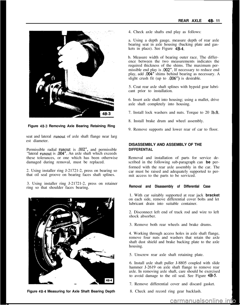
4. For replacement of the bearing parts, first remove
retaining ring by cutting off with a chisel. See Figure4B-3.
5. Press off bearing, using rear pinion bearing
remover J-22912.
Installation
CAUTION: Fasteners in the following steps b are im-
portant attaching parts in that they could at&t
tee
performance of vital components and systems, and-
/or could result in major
repair expense.They must
be replaced with one of the same part number or with
an equivalentpart ifreplacement becomes necessary.
Do not use a replacement part of lesser quality or
substitute design Torque values must be used as
specified
during reassembly to assure proper reten-
tion of these parts.1. Check radial runout of axle shaft at ball bearing
Page 242 of 625
REAR AXLE40- 11
Figure
48-3 Removing Axle Bearing Retaining Ring
seat and lateral runout of axle shaft flange near larg
est diameter.
Permissible radial runout is .002”, and permissible
“lateral runout is
.OO4”. An axle shaft which exceeds
these tolerances, or one which has been otherwise
damaged during removal, must be replaced.
2. Using installer ring J-21721-2, press on bearing so
that oil seal groove on bearing faces shaft splines.
3. Using installer ring J-21721-2, press on retainer
ring so that shoulder faces bearing.
Figure 48.4 Measuring for Axle Shaft Bearing Depth4. Check axle shafts end play as follows:
a. Using a depth gauge, measure depth of rear axle
bearing seat in axle housing (backing plate and gas-
kets in place). See Figure
4B-4.b. Measure width of bearing outer race. The differ-
ence between the two measurements indicates the
required thickness of the shims. The maximum per-
missible end play is .002”. If necessary to reduce end
play, add
,004” shims behind bearing as necessary. A
slight crush fit (up to ,006”) is desirable.
5. Coat rear axle shaft splines with hypoid gear lubri-
cant prior to installation.
6. Insert axle shaft into housing; using a mallet, drive
axle shaft completely into housing.
7. Install lock washers and nuts. Torque to 20
Ib.ft.8. Install brake drum and wheel assembly.
9. Remove supports and lower rear of car to floor.
DISASSEMBLY AND ASSEMBLY OF THE
DIFFERENTIALRemoval and installation of parts for service de-
scribed in the following sub-paragraph can be per-
formed with the rear axle assembly in the car. The
car must be raised and adequately supported to per-
mit access to the parts to be serviced.
Removal and Disassembly of Differential Case1. With car suitably supported at rear jack bracket
on each side, remove differential cover bolts and let
lubricant drain into suitable container.
2. Disconnect left end of track rod and wire to left
shock absorber.
3. Remove both rear wheels and brake drums.
4. Working through access holes in axle shaft flange,
remove four nuts and washers that retain the axle
shaft dust shield and brake backing plate to the axle
housing.
5. Unscrew rear axle shaft retaining plate.
6. Install axle shaft puller J-8805 coupled with slide
hammer J-2619 on axle shaft flange to remove rear
axle. In removing axle shaft, care should be exercised
to avoid damage to the oil seal. See Figure
4B-5.7. Remove differential cover and discard gasket.
8. Check and record ring gear backlash.
Page 243 of 625
4S- 121973 OPEL SERVICE MANUAL
12. Insert adapter J-2241-1 1 in differential case bear-
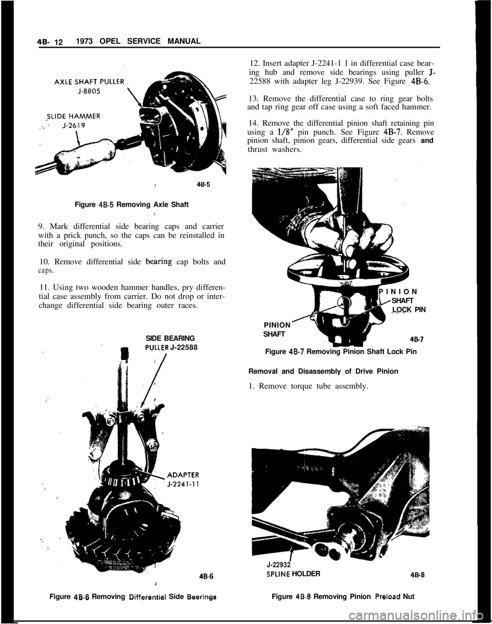
ing hub and remove side bearings using puller J-22588 with adapter leg J-22939. See Figure
4B-6.13. Remove the differential case to ring gear bolts
and tap ring gear off case using a soft faced hammer.
14. Remove the differential pinion shaft retaining pin
using a
l/8” pin punch. See Figure 4B-7. Remove
pinion shaft, pinion gears, differential side gears and
thrust washers.
Figure 46.5 Removing Axle Shaft18
9. Mark differential side bearing caps and carrier
with a prick punch, so the caps can be reinstalled in
their original positions.
10. Remove differential side bearing cap bolts and
caps.11. Using two wooden hammer handles, pry differen-
tial case assembly from carrier. Do not drop or inter-
change differential side bearing outer races.
SIDE BEARING
PVLLER J-2258846.6
/NFigure
48-S Removing Differentiel Side BesrlngaPINION
SHAFTPINION
kSHAFT
LOCK PIN487
Figure 48-7 Removing Pinion Shaft Lock Pin
Removal and Disassembly of Drive Pinion
1. Remove torque tube assembly.
J-22932
SPLINE HOLDER4&8
Figure
48-E Removing Pinion Preload Nut
Page 245 of 625
46. 141973 OPEL SERVICE MANUAL
2. Install rear pinion bearing outer race (without
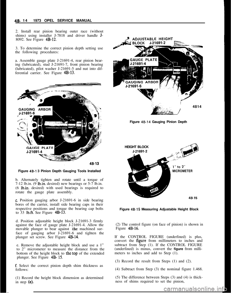
shims) using installer J-7818 and driver handle
J-8092. See Figure 4B-12.
3. To determine the correct pinion depth setting use
the following procedures:
a. Assemble gauge plate J-21691-4, rear pinion bear-
ing (lubricated), stud J-21691-7, front pinion bearing
(lubricated), pilot washer J-21691-5 and nut into dif-
ferential carrier. See Figure 4B-13.
‘1GAUGING ARBOR
Figure 48-l 3 Pinion Depth Gauging Tools Installed
b. Alternately tighten and rotate until a torque of
7-12 lb.in. (9 Ibin. desired) new bearings or 5-7 lb.in.
(6 lb.in. desired) with used bearings is required to
rotate the gauge plate assembly.
c. Position gauging arbor J-21691-6 in side bearing
bores of the carrier, install side bearing caps in their
respective positions and torque the bearing cap bolts
to 33
lb.ft. See Figure 4B-13.
d. Position adjustable height block J-21691-3 firmly
against the face of gauge plate J-21691-4. Allow the
movable plunger to bear against
#the machined sur-
face of gauging arbor J-21691-6 and tighten the
plunger set screw. See Figure
4B-14.e. Remove the adjustable height block and use a 1”
to 2” micrometer to measure the distance from the
bottom of the height block to
thetop of the extended
plunger. See Figure
4B- 15.
f. Select the correct pinion depth shim thickness as
follows:
(1) Record the height block dimension as determined
in step
(e).
I4814
/Figure 48.14 Gauging Pinion Depth
HEIGHT BLOCK
MICROMETER
48-15Figure 4B-15 Measuring Adjustable Height Block
(2) The control figure (on face of pinion) is shown in
Figure
4B-16.If the CONTROL FIGURE (underlined) is plus,
convert the figure from millimeters to inches and
subtract from Step (1). If the CONTROL FIGURE
(underlined) is minus, convert the figure from milli-
meters to inches and add to Step (1).
(3) Record the result from Steps (1) and (2).
(4) Subtract from Step (3) the nominal figure 1.468.
(5) The difference between Steps (3) and (4) is thick-
ness of shims required to set the pinion,
Page 248 of 625
6. Before installing, shims must be measured to in-
sure that the proper thickness is being used. Install
shims of correct thickness to obtain desired clearance
and reassemble and install pinion shaft lock pin. In-
stall thrust washers with concave side towards differ-
ential case.
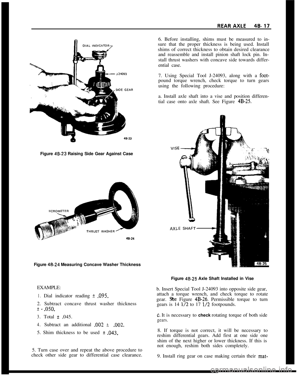
7. Using Special Tool J-24093, along with a foot-pound torque wrench, check torque to turn gears
using the following procedure:
a. Install axle shaft into a vise and position differen-
tial case onto axle shaft. See Figure
4B-25.Figure 48-23 Raising Side Gear Against Case
Figure 48.24 Measuring Concave Washer Thickness
AX,EXAMPLE:
1.Dial indicator reading * .095.
2. Subtract concave thrust washer thickness
+ -.oso.
3.Total + ,045.
4.Subtract an additional .002 *.002.
5. Shim thickness to be used
+ .043.
5. Turn case over and repeat the above procedure to
check other side gear to differential case clearance.Figure 48.25 Axle Shaft Installed in Vise
b. Insert Special Tool J-24093 into opposite side gear,
attach a torque wrench, and check torque to rotate
gear. S& Figure
4B-26. Permissible torque to turn
gears is 14
l/2 to 17 l/2 footpounds.
c. It is necessary to check rotating torque of both side
gears.8. If torque is not correct, it will be necessary to
reshim differential gears. Add first at one side one
shim of the next higher or lower thickness. If this is
not enough, reshim both sides completely.
9. Install ring gear on case making certain their mat-