torque OPEL GT-R 1973 Repair Manual
[x] Cancel search | Manufacturer: OPEL, Model Year: 1973, Model line: GT-R, Model: OPEL GT-R 1973Pages: 625, PDF Size: 17.22 MB
Page 249 of 625
48. 181973 OPEL SERVICE MANUAL
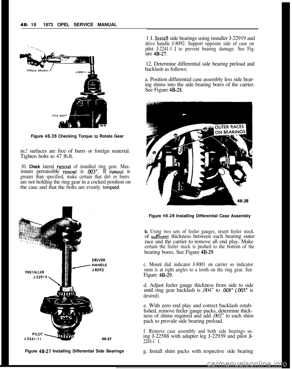
Figure 48.26 Checking Torque
to Rotate Gear
in;! surfaces are free of burrs or foreign material.
Tighten bolts to 47 lb.ft.
10. Check lateral runout of installed ring gear. Max-imum permissible runout is
.003”. If runout is
greater than specified, make certain that dirt or burrsare not holding the ring gear in a cocked position on
the case and that the bolts are evenly
torqued.Figure 48-27 Installing Differential Side Bearings
g. Install shim packs with respective side bearing1 I.
In.stall side bearings using installer J-22919 and
drive handle J-8092. Support opposite side of case on
pilot J-2241-1
1 to prevent bearing damage. See Fig-ure
4B-27.12. Determine differential side bearing preload and
backlash as follows:
a. Position differential case assembly less side bear-
ing shims into the side bearing bores of the carrier.
See Figure
4B-28.Figure 48.28 Installing Differential Case Assembly
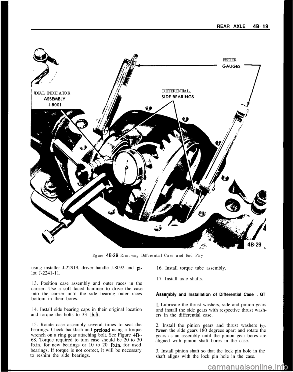
b. Using two sets of feeler gauges, insert feeler stockof suffcent thickness between each bearing outer
race and the carrier to remove all end play. Make
certain the feeler stock is pushed to the bottom of thebearing bores. See Figure
4B-29.
c. Mount dial indicator J-8001 on carrier so indicator
stem is at right angles to a tooth on the ring gear. SeeFigure
4B-29.d. Adjust feeler gauge thickness from side to side
until ring gear backlash is ,004” to
.OO8” (.005” is
desired).e. With zero end play and correct backlash estab-
lished, remove feeler gauge packs, determine thick-
ness of shims required and add ,002” to each shim
pack to provide side bearing preload.
f. Remove case assembly and both side bearings us-ing J-22588 with adapter leg J-22939 and pilot
J-
2241-l 1.
Page 250 of 625
REAR AXLE48.19FEELER
DIAL INDICATORDIFFERENTIAL
Figure 48.29 Removing Differential Case and End Playusing installer J-22919, driver handle J-8092 and pi-
lot J-2241-11.16. Install torque tube assembly.
17. Install axle shafts.
13. Position case assembly and outer races in the
carrier. Use a soft faced hammer to drive the case
into the carrier until the side bearing outer races
bottom in their bores.Assynbly and Installation of Differential Case
- GT
14. Install side bearing caps in their original location
and torque the bolts to 33
Ib.ft.
1. Lubricate the thrust washers, side and pinion gears
and install the side gears with respective thrust wash-
ers in the differential case.
15. Rotate case assembly several times to seat the
bearings. Check backlash and preload using a torque
wrench on a ring gear attaching bolt. See Figure
4B--68. Torque required to turn case should be 20 to 30
lb.in. for new bearings or 10 to 20 Ibin. for used
bearings. If torque is not correct, it will be necessary
to reshim the side bearings.2. Install the pinion gears and thrust washers be-tween the side gears 180 degrees apart and rotate the
gears as an assembly until the pinion gear bores are
aligned with pinion shaft bores in the case.
3. Install pinion shaft so that the lock pin hole in the
shaft aligns with the lock pin hole in the case.
Page 251 of 625
49- 201973 OPEL SERVICE MANUAL
IN.LB. TORQUE
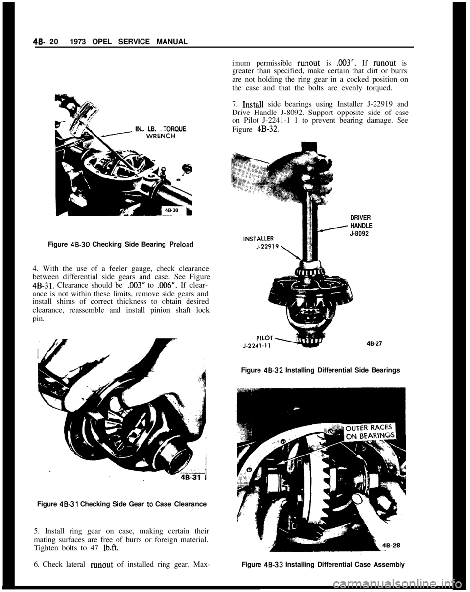
Figure 48.30 Checking Side Bearing Preload
4. With the use of a feeler gauge, check clearance
between differential side gears and case. See Figure
4B-31. Clearance should be ,003” to X106”. If clear-
ance is not within these limits, remove side gears and
install shims of correct thickness to obtain desired
clearance, reassemble and install pinion shaft lock
pin.
Figure 48.31 Checking Side Gear to Case Clearance
5. Install ring gear on case, making certain their
mating surfaces are free of burrs or foreign material.
Tighten bolts to 47
lb.ft.
6. Check lateral runout of installed ring gear. Max- imum permissible
runout is X03”. If runout is
greater than specified, make certain that dirt or burrs
are not holding the ring gear in a cocked position on
the case and that the bolts are evenly torqued.
7.
Imtall side bearings using Installer J-22919 and
Drive Handle J-8092. Support opposite side of case
on Pilot J-2241-1 1 to prevent bearing damage. See
Figure
4B-32.
DRIVER
HANDLE
J-8092
4B.27
Figure 48-32 Installing Differential Side Bearings
Figure
48.33 Installing Differential Case Assembly
Page 253 of 625
48. 221973 OPEL SERVICE MANUAL
9. Position
case assembly and outer races in the car-
rier. Use a soft-faced hammer to drive the case into
the carrier until the side bearing outer races bottom
in their bores.
10. Install side bearing caps in their original location
and torque the bolts to 33
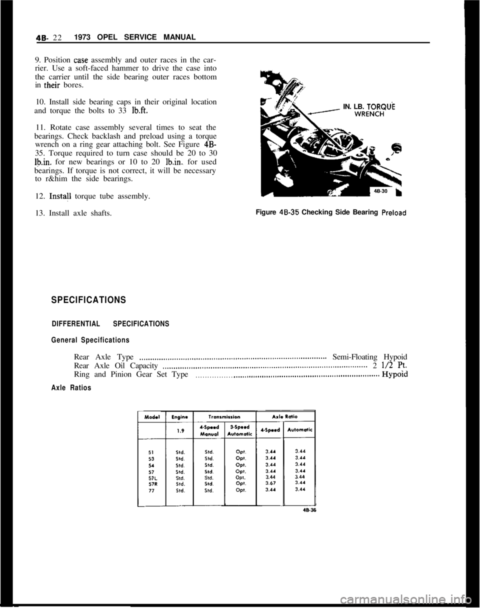
lb.ft.IN. LB. TORQUL
11. Rotate case assembly several times to seat the
bearings. Check backlash and preload using a torque
wrench on a ring gear attaching bolt. See Figure 4B-
35. Torque required to turn case should be 20 to 30
Ib.in. for new bearings or 10 to 20 lb.in., for used
bearings. If torque is not correct, it will be necessary
to r&him the side bearings.
12. Insta!l torque tube assembly.
13. Install axle shafts.Figure 48.35 Checking Side Bearing
Preload
SPECIFICATIONS
DIFFERENTIAL SPECIFICATIONS
General SpecificationsRear Axle Type
.,,...,,,...,,_...._..,,...,,,...,,,....,,.,...,,.,,...,,..,,,........................ Semi-Floating Hypoid
Rear Axle Oil Capacity
..____,,...,,,...,.,..,............,,..,,..,,................................................. 2 l/2 7’.Ring and Pinion Gear Set Type
. . . . . . . . . . . . . . . . . .._................................................................Hypold
Axle Ratios
Page 254 of 625
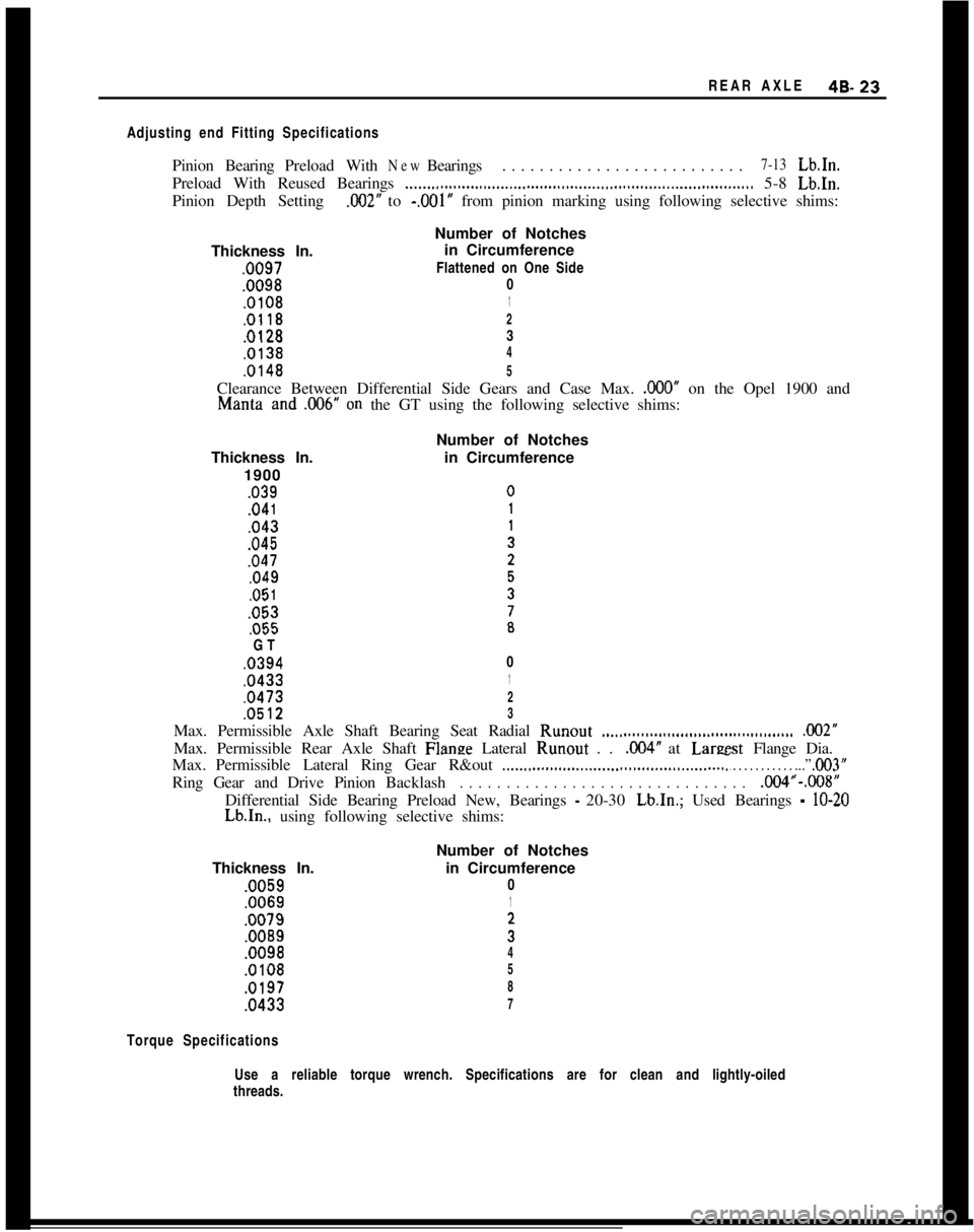
REAR AXLE49.23
Adjusting end Fitting SpecificationsPinionBearingPreloadWith
NewBearings. . . . . . . . . . . . . . . . . . . . . . . . . .7-13Lb.In.
Preload With Reused Bearings
__.._..I...................,.................,,...................,,............ 5-8 Lb.In.
Pinion Depth Setting
.002” to -.OOl’ from pinion marking using following selective shims:
Number of Notches
Thickness In.in Circumference.0097Flattened on One Side
.00980
.01081
.01182
.01283
.01384
.01485Clearance Between Differential Side Gears and Case Max.
,000” on the Opel 1900 andManta and
,006” on the GT using the following selective shims:
Thickness In.
1900
,039.04
1,043,045,047,049.05
1,053,055
GT
.0394
.0433
.0473Number of Notches
in Circumference
0
1
2
.05123Max. Permissible Axle Shaft Bearing Seat Radial Runout
.._......................................... ,002”Max. Permissible Rear Axle Shaft Flanze Lateral Runout . .
,004” at Lareest Flange Dia.
Max.Permissible Lateral Ring Gear R&out
._.._,,.........._.....,........................... T . . . . . . . . . . . ...” ,003”RingGearandDrivePinionBacklash
. . . . . . . . . . . . . . . . . . . . . . . . . . . . . . .,004”-.008”
Differential Side Bearing Preload New, Bearings
- 20-30 Lb.In.; Used Bearings - lo-20Lb.In., using following selective shims:
Thickness In..0059.0069
.0079
.0089
.0098
.0108
.0197
.0433Number of Notches
in Circumference
0
1
;
4
5
8
7
Torque SpecificationsUse a reliable torque wrench. Specifications are for clean and lightly-oiled
threads.
Page 255 of 625
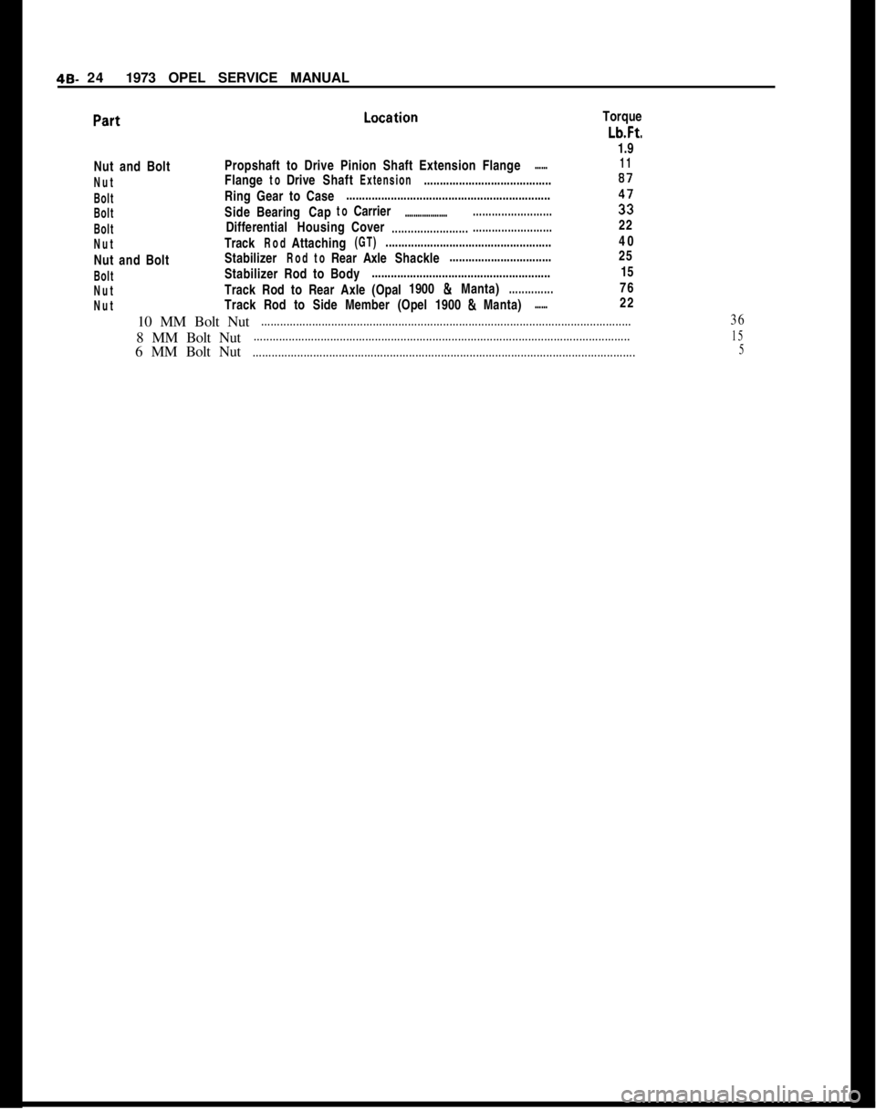
49- 241973 OPEL SERVICE MANUAL
Torque
Lb.Ft.
1.9Nut and BoltPropshaft to Drive Pinion Shaft Extension Flange
......11
NutFlange
toDriveShaftExtension........................................87
BoltRing Gear to Case................................................................
BoltSideBearingCaptoCarrier.............................................i;
BoltDifferentialHousingCover.................................................22
NutTrackRodAttaching(GT)....................................................40
Nut and BoltStabilizer
RodtoRearAxleShackle................................25
BoltStabilizer Rod to Body........................................................15
NutTrack Rod to Rear Axle (Opal1900 & Manta)..............76
NutTrack Rod to Side Member (Opel 1900 & Manta)......22
10 MM Bolt Nut
....................................................................................................................368 MM Bolt Nut
......................................................................................................................156 MM Bolt Nut
........................................................................................................................5
Page 256 of 625
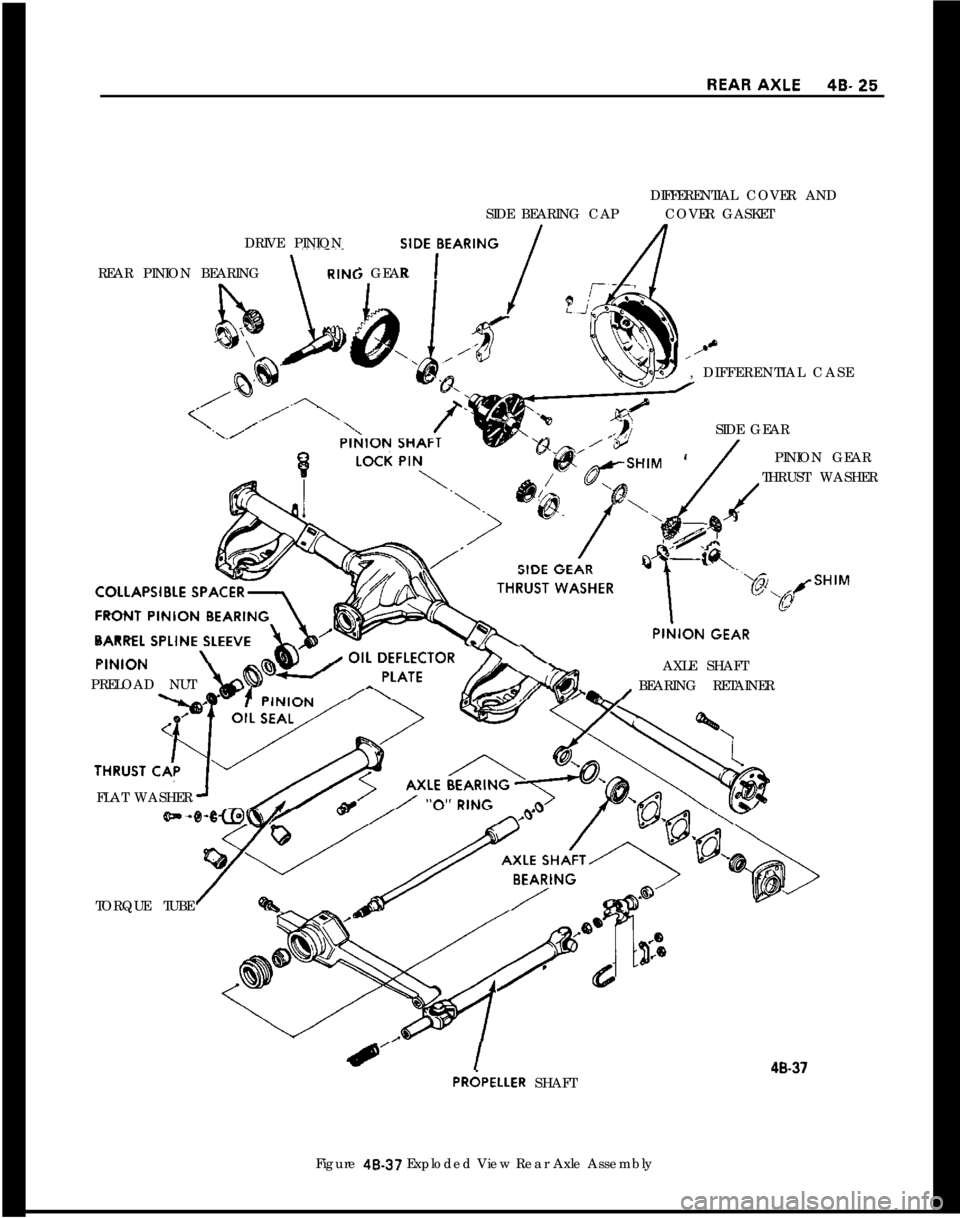
DIFFERENTIAL COVER AND
SIDE BEARING CAPCOVER GASKET
DRIVE PINIONSlDE,BEARlNG /; GEAR REAR PINION BEARINGx
\PRELOAD NUT, DIFFERENTIAL CASE
SIDE GEAR
PINION GEAR
THRUST WASHER
AXLE SHAFT
BEARING RETAINER
FLAT WASHER
TORQUE TUBE40.37PRdPELLER SHAFT
Figure 48-37 Exploded View Rear Axle Assembly
Page 265 of 625
5A- 61973 OPEL SERVICE MANUAL
ing on dusty and sandy roads - the filter and sound
deadener should occasionally be replaced. To do so,
brake booster has to be removed without detaching
brake master cylinder.
Proceed as follows:
1. Remove protective cap (boot).
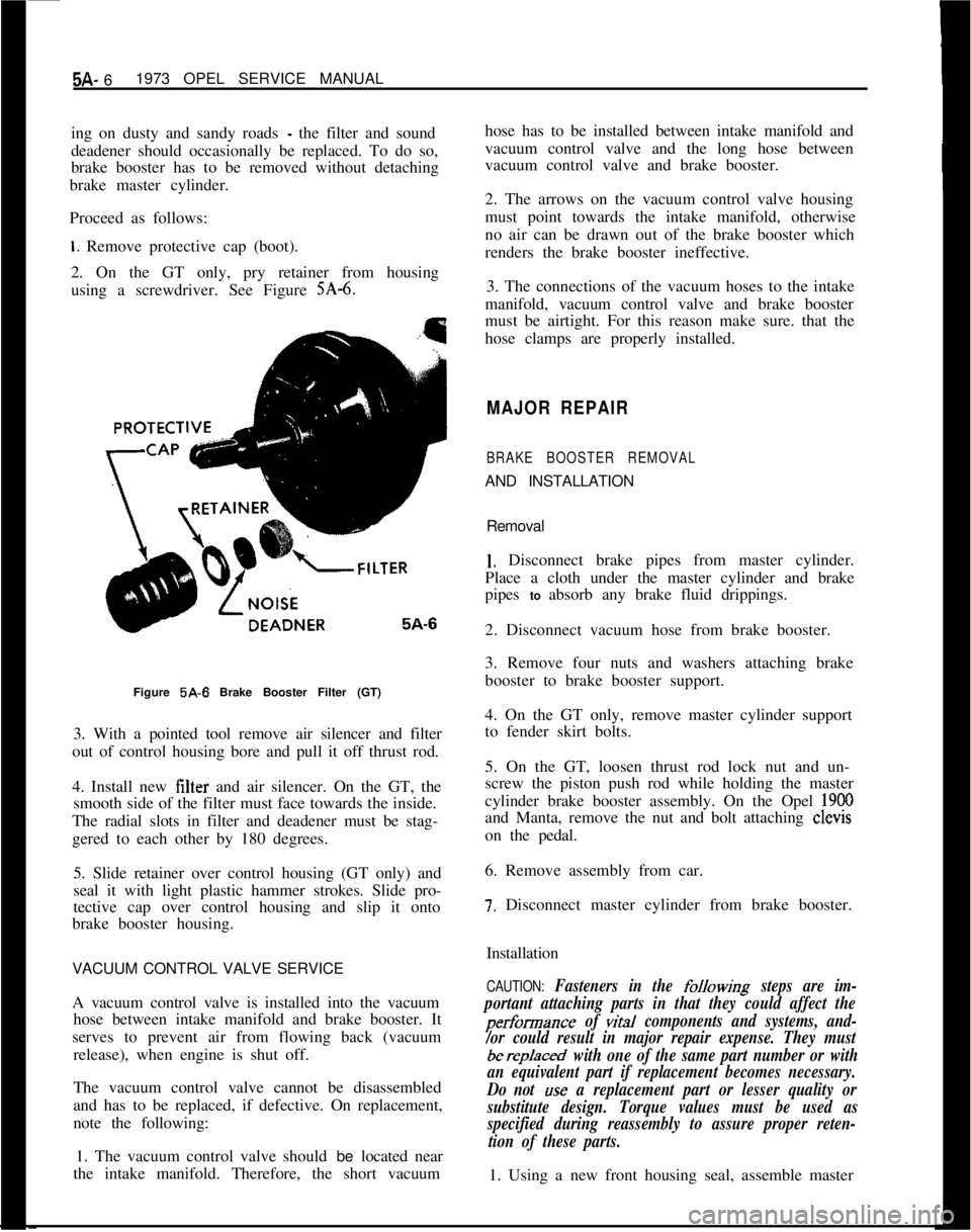
2. On the GT only, pry retainer from housing
using a screwdriver. See Figure
SA-6.Figure 5A-6 Brake Booster Filter (GT)
3. With a pointed tool remove air silencer and filter
out of control housing bore and pull it off thrust rod.
4. Install new filter and air silencer. On the GT, the
smooth side of the filter must face towards the inside.
The radial slots in filter and deadener must be stag-
gered to each other by 180 degrees.
5. Slide retainer over control housing (GT only) and
seal it with light plastic hammer strokes. Slide pro-
tective cap over control housing and slip it onto
brake booster housing.
VACUUM CONTROL VALVE SERVICE
A vacuum control valve is installed into the vacuum
hose between intake manifold and brake booster. It
serves to prevent air from flowing back (vacuum
release), when engine is shut off.
The vacuum control valve cannot be disassembled
and has to be replaced, if defective. On replacement,
note the following:
1. The vacuum control valve should be located near
the intake manifold. Therefore, the short vacuumhose has to be installed between intake manifold and
vacuum control valve and the long hose between
vacuum control valve and brake booster.
2. The arrows on the vacuum control valve housing
must point towards the intake manifold, otherwise
no air can be drawn out of the brake booster which
renders the brake booster ineffective.
3. The connections of the vacuum hoses to the intake
manifold, vacuum control valve and brake booster
must be airtight. For this reason make sure. that the
hose clamps are properly installed.
MAJOR REPAIR
BRAKE BOOSTER REMOVALAND INSTALLATION
Removal
1. Disconnect brake pipes from master cylinder.
Place a cloth under the master cylinder and brake
pipes to absorb any brake fluid drippings.
2. Disconnect vacuum hose from brake booster.
3. Remove four nuts and washers attaching brake
booster to brake booster support.
4. On the GT only, remove master cylinder support
to fender skirt bolts.
5. On the GT, loosen thrust rod lock nut and un-
screw the piston push rod while holding the master
cylinder brake booster assembly. On the Opel
1900and Manta, remove the nut and bolt attaching clevis
on the pedal.
6. Remove assembly from car.
7. Disconnect master cylinder from brake booster.
Installation
CAUTION: Fasteners in the folkwing steps are im-
portant attaching parts in that they could affect the
performance of vital components and systems, and-
/or could result in major repair expense. They must
berep/aced, with one of the same part number or with
an equivalent part if replacement becomes necessary.
Do not
use a replacement part or lesser quality or
substitute design. Torque values must be used as
specified during reassembly to assure proper reten-
tion of these parts.1. Using a new front housing seal, assemble master
Page 266 of 625
POWER BRAKE BOOSTER AND MASTER CYLINDER5A- 7cylinder to brake booster and torque nuts to 14
Ib.ft.on the GT and 12
lb.ft. on the Opel 1900 and Manta.
2. Position assembly into brake booster bracket and,
on the GT only, thread piston push rod onto the
thrust rod.
3. Install brake booster to support attaching washers
and nuts and tighten to 11
lb.ft. of torque.
4. On the GT install master cylinder support to inner
fender skirt bolts.
5. Connect vacuum hose to brake booster.
6. By turning the piston push rod on the thrust rod,
(GT only) adjust until the brake pedal free travel is
l/4 inch and tighten the lock nut.
7. Connect brake pipes to master cylinder and bleed
brakes.
MASTER CYLINDER OVERHAUL. GT
Removal of Master Cylinder1. Disconnect the two brake pipes from the master
cylinder.
2. Remove the front support to skirt attaching bolts,
the cylinder to booster retaining nuts and lift out
master cylinder.
Disassembly1. Prior to brake master cylinder disassembly, pour
brake fluid out of brake fluid reservoir, remove reser-
voir from master cylinder and take sealing plugs out
of housing.
2. Screw static pressure valve(s) out of housing.
3. To facilitate disassembly, push piston somewhat
into cylinder and insert a rounded off piece of weld-
ing rod approx.
.12 in. thick into feed port to retain
piston in this position.
4. Remove stop screw and snap ring out of housing
and take out both pistons together with springs.
5. Remove stop screw from piston for rear brake
circuit and remove all component parts. Remove
also all component parts from intermediate piston of
front brake circuit.
Cleaning and Checking1. Clean parts with genuine brake fluid, Delco Su-
preme No. 11, or equivalent. Do not use any other
cleaning solvents. Dry with compressed air. Free up
compensating and feed ports.2. Polish cylinder bore of housing with crocus cloth.
If lapping scores and rust spots are still noticeable,
replace brake master cylinder assembly.
3. Check inner components for damage and replace,
if required. The rubber seals and static pressure valve
always have to be replaced.
Assembly1. Assemble front and rear brake circuit pistons.
Prior to assembly coat rubber seals with brake fluid.
2. Coat cylinder bore, piston sliding surfaces and
seals with brake fluid.
3. Insert preassembled intermediate piston for front
brake circuit together with thrust spring and spring
seat into clyinder bore. The smaller diameter of the
tapered thrust spring must face piston.
4. With a drift, push piston (against spring pres-
sure) into housing and insert a piece of welding rod
into feed port of front brake circuit to retain piston.
5. Install stop screw with new seal ring into housing
and tighten.
6. Insert preassembled piston for rear brake circuit
into cylinder bore and install snap ring into groove
in housing.
7. Check piston fof free movement by moving it to
and fro. If required, place washers under the head of
the stop screw.
8. Lightly push piston into housing and remove
piece of welding rod out of feed port of front brake
circuit.
9. With a rounded off piece of welding rod
(.020 -
,024 in.) check whether compensating ports are free.
10. Screw in new static pressure valve(s).
11. Coat new sealing plugs with brake fluid and in-
sert them into housing. Push twin brake fluid con-
tainer into sealing plugs and install screen and cover
with seal ring.
Installation1. Install master cylinder onto brake booster with
washers and nuts. Torque to 14
lb.ft.2. Attach the front mounting bracket.
3. Install brake lines on master cylinder, and bleed
brakes.
Page 268 of 625
POWER BRAKE BOOSTER AND MASTER CYLINDER5A- 9NOTE: Snap ring should not be reused.5. Remove primary and secondary pistons from cyl-
inder.
6. Remove check valve by unscrewing check valve
connection.
Cleaning and Checking
1. Clean parts with genuine brake fluid, Delco Su-
preme No. 11, or equivalent. Do not use any other
cleaning solvents. Dry with compressed air. Free up
compensating and feed parts.
2. Inspect cylinder bore for pits, scoring, cracks,
nicks or other defects.
NOTE: Whenever the master cylinder is overhauled,
a new repair kit must be used.
Assembly
NOTE:
Before reassembly double check that there
is no foreign particles in the master
cyIinder bore
or on any parts that are to be assembled into it.1. Coat master cylinder bore with clean brake fluid
and install secondary and primary pistons.
2. Install new snap ring while holding primary piston
in a forward position.
3. Install check valve spring, check valve and check
valve connector and torque to 26
Ib.ft.4. Install stop screw.
5. Lubricate reservoir seals and remount on master
cylinder body.
6. Install reservoir clips into reservoir and mount
reservoir onto master cylinder without distorting
seals. Do not force reservoir onto master cylinder.
7. Position reservoir cover onto reservoir.
Installation
1. Mount master cylinder to brake booster, using a
new front housing seal if old one is damaged or dis-
torted. Torque nuts to 12
lb.ft.2. Install brake pipes to master cylinder and bleed
brakes.
SPECIFICATIONS
GENERAL SPECIFICATIONSBrake Booster Size
..............................................................................................................7 in.
BrakeBoostRatio
-(GT)..........................................................................................2.06to1Brake Boost Ratio
- (Opel 1900 and Manta)............................................................2.64 to 1
NameTorque
Nut
Nut
Lb.Ft.Master Cylinder to Brake Booster
(GT) .__......._.._...._.........
Master Cylinder to Brake Booster (Opel 1900 and
Manta)14
12Brake ‘Booster to Support
.._...._..........................................11