Peugeot Boxer 2002.5 Owner's Manual
Manufacturer: PEUGEOT, Model Year: 2002.5, Model line: Boxer, Model: Peugeot Boxer 2002.5Pages: 182, PDF Size: 2.81 MB
Page 141 of 182
16-09-2002
PRACTICAL INFORMATION
140
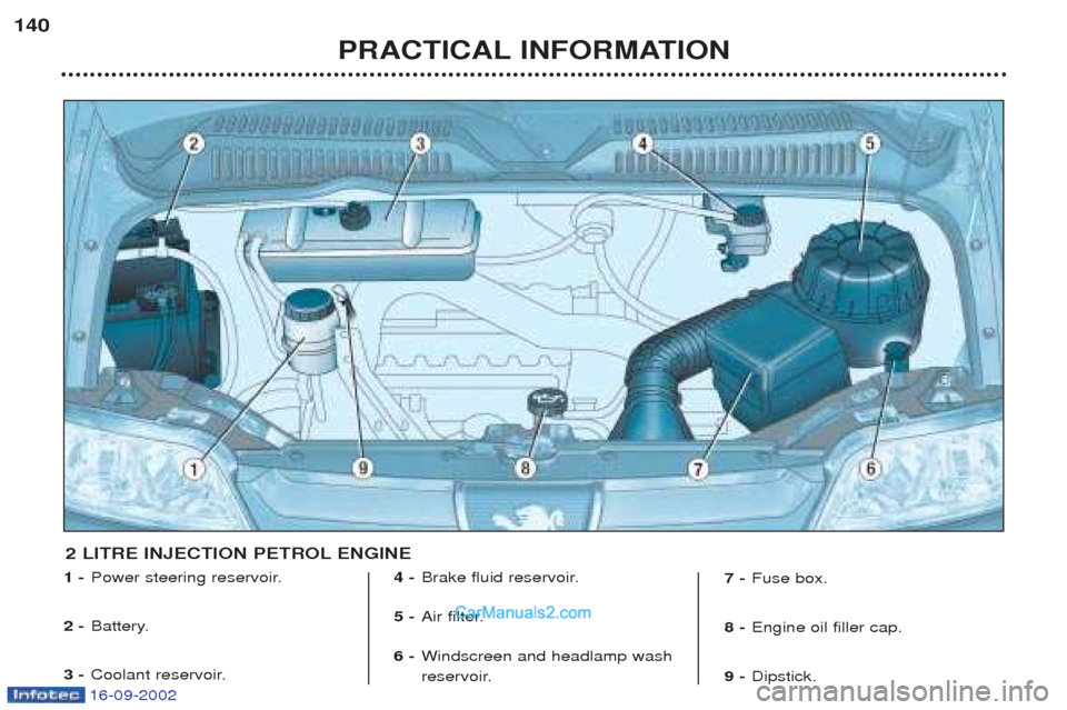
1 -
Power steering reservoir.
2 - Battery.
3 - Coolant reservoir. 4 -
Brake fluid reservoir.
5 - Air filter.
6 - Windscreen and headlamp wash
reservoir. 7 -
Fuse box.
8 - Engine oil filler cap.
9 - Dipstick.
2 LITRE INJECTION PETROL ENGINE
Page 142 of 182
16-09-2002
PRACTICAL INFORMATION141
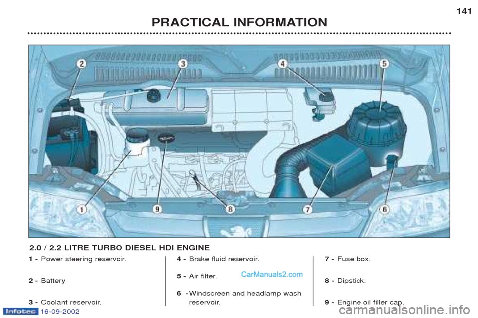
1 -
Power steering reservoir.
2 - Battery
3 - Coolant reservoir. 4 -
Brake fluid reservoir.
5 - Air filter.
6 - Windscreen and headlamp wash
reservoir. 7 -
Fuse box.
8 - Dipstick.
9 - Engine oil filler cap.
2.0 / 2.2 LITRE TURBO DIESEL HDI ENGINE
Page 143 of 182
16-09-2002
PRACTICAL INFORMATION
142
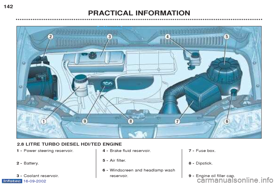
1 -
Power steering reservoir.
2 - Battery.
3 - Coolant reservoir. 4 -
Brake fluid reservoir.
5 - Air filter.
6 - Windscreen and headlamp wash
reservoir. 7 -
Fuse box.
8 - Dipstick.
9 - Engine oil filler cap.
2.8 LITRE TURBO DIESEL HDI/TED ENGINE
Page 144 of 182
16-09-2002
PRACTICAL INFORMATION143
CHECKING THE LEVELS Oil level ☞ Check the level regularly and top
up between changes. The maxi-mum consumption is 0.5 l per1000 km. Check the level with the vehicle level, engine cold, using the dips-tick.
Dipstick
There are two marks onthe dipstick: A= maximum.
Never fill past this mark.B = minimum.
To maintain the reliability
of engines and emission control systems, the useof additives in engine oilis prohibited.
Oil change According to the information given in
"PEUGEOT SERVICING" .
W ARNING: avoid used oil from
coming into prolonged contact withthe skin.
V iscosity selection
In all cases, the oil selected must meet the manufacturer's require-ments. Brake fluid level: - the level must always be between the MINIMUM and MAXIMUM
marks in the reservoir.
- if the level drops substantially,
contact a PEUGEOT dealer imme-
diately.
Fluid change: - must be carried out according to the manufacturer's servicing sche-dule.
- use fluids approved by the manu-
facturer, which fulfil DOT4 stan-dards.
W ARNING: brake fluid is harmful to
health and very corrosive. Avoid allcontact with the skin. Cooling system Use the fluid approved by the manu-
facturer. When the engine is warm, the tem- perature of the coolant is controlled
by the engine fan. As this fan canoperate with the ignition key remo-ved and because the cooling systemis pressurised, wait for at least onehour after the engine has stoppedbefore carrying out any work. Slacken the cap to the first notch torelease the pressure to prevent anyrisk of scalding. When the pressurehas dropped, remove the cap andtop up the level. Note:
the coolant does not need to
be changed. Used oil Do not dispose of used oil, brake fluid or coolant into drains or into theground. Power steering reservoir ☞ Open the reservoir, with the engi-
ne at ambient temperature. Thelevel should always be above theMIN. mark and close to the MAX.mark.
W indscreen and headlamp
wash reservoir For best quality cleaning and for your
safety, we recommend that you useproducts approved by PEUGEOT(7.5 litres with headlamp wash).
Page 145 of 182
16-09-2002
Only use products
approved by Automobiles
PEUGEOT.
To ensure best perfor-
mance from components
as important as the power steering and the braking system,PEUGEOT selects and offersquite specific products.
CHECKS Battery
At the start of winter, have your bat-
tery checked by a PEUGEOT dealer. Air filter and pollen filter Have the filter elements replaced
regularly. If you drive in dusty
conditions, change them twice asoften. Brake pads Brake pad wear depends on the style of driving, in particular forvehicles which are used in town,over short distances. It may benecessary to check the thickness ofthe pads, even between services. Handbrake Where the handbrake travel is too great or there is a reduction in theperformance of the system, thehandbrake should be adjusted, evenbetween services. Have the system checked by a
PEUGEOT dealer. Manual gearbox This does not need an oil change. Check the level, according to themanufacturer's servicing schedule. Automatic gearbox This does not need an oil change. Have the level checked by a
PEUGEOT dealer, according to themanufacturer's servicing schedule. Oil filter
Change the filter regularly, in accor- dance with the servicing schedule.
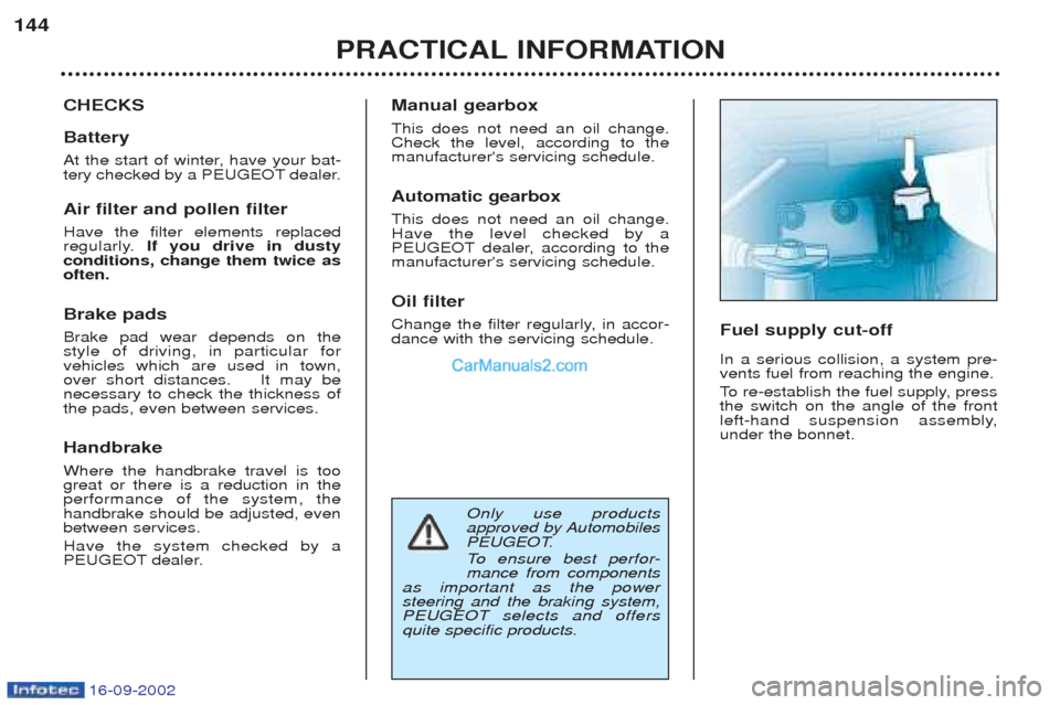
Fuel supply cut-off In a serious collision, a system pre- vents fuel from reaching the engine.
To
re-establish the fuel supply, press
the switch on the angle of the front
left-hand suspension assembly,under the bonnet.
PRACTICAL INFORMATION
144
Page 146 of 182
16-09-2002
PRACTICAL INFORMATION145
CHANGING A WHEEL Parking the vehicle ☞
Park the vehicle on level, stable and non-slippery ground.
☞ Apply the handbrake, switch offthe ignition and engage first orreverse gear (position Pfor the
automatic gearbox).
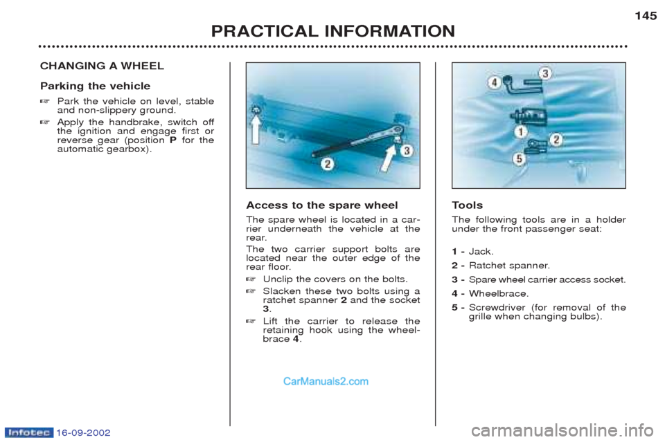
Tools
The following tools are in a holderunder the front passenger seat: 1 - Jack.
2 - Ratchet spanner.
3 - Spare wheel carrier access socket.
4 - Wheelbrace.
5 - Screwdriver (for removal of the grille when changing bulbs).
Access to the spare wheel The spare wheel is located in a car- rier underneath the vehicle at the
rear. The two carrier support bolts are located near the outer edge of the
rear floor. ☞
Unclip the covers on the bolts.
☞ Slacken these two bolts using a ratchet spanner 2and the socket
3 .
☞ Lift the carrier to release theretaining hook using the wheel-brace 4.
Page 147 of 182
16-09-2002
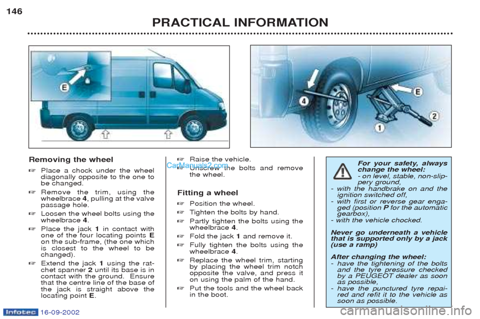
Removing the wheel ☞Place a chock under the wheel diagonally opposite to the one tobe changed.
☞ Remove the trim, using thewheelbrace 4, pulling at the valve
passage hole.
☞ Loosen the wheel bolts using thewheelbrace 4.
☞ Place the jack 1in contact with
one of the four locating points E
on the sub-frame, (the one whichis closest to the wheel to bechanged).
☞ Extend the jack 1using the rat-
chet spanner 2until its base is in
contact with the ground. Ensurethat the centre line of the base ofthe jack is straight above thelocating point E. ☞
Raise the vehicle.
☞ Unscrew the bolts and removethe wheel.
Fitting a wheel ☞ Position the wheel.
☞ Tighten the bolts by hand.
☞ Partly tighten the bolts using the wheelbrace 4.
☞ Fold the jack 1and remove it.
☞ Fully tighten the bolts using thewheelbrace 4.
☞ Replace the wheel trim, startingby placing the wheel trim notchopposite the valve, and press iton using the palm of the hand.
☞ Put the tools and the wheel backin the boot. For your safety, always change the wheel: - on level, stable, non-slip- pery ground,
- with the handbrake on and the ignition switched off,
- with first or reverse gear enga- ged (position Pfor the automatic
gearbox),
- with the vehicle chocked. Never go underneath a vehicle that is supported only by a jack(use a ramp) After changing the wheel: - have the tightening of the bolts and the tyre pressure checkedby a PEUGEOT dealer as soonas possible,
- have the punctured tyre repai- red and refit it to the vehicle assoon as possible.
PRACTICAL INFORMATION
146
Page 148 of 182
16-09-2002
PRACTICAL INFORMATION147
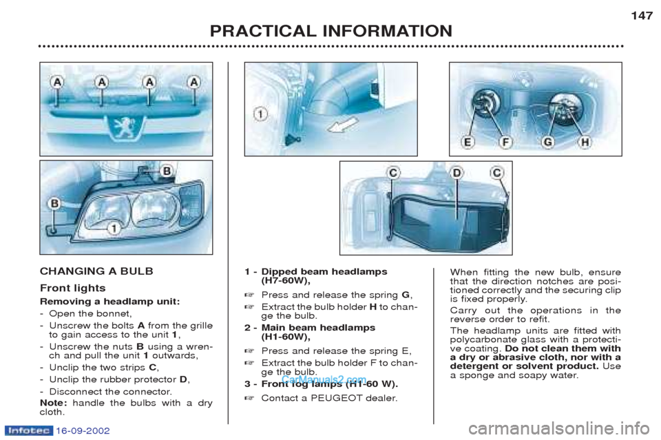
CHANGING A BULB Front lights Removing a headlamp unit: -
Open the bonnet,
- Unscrew the bolts Afrom the grille
to gain access to the unit 1,
- Unscrew the nuts Busing a wren-
ch and pull the unit 1outwards,
- Unclip the two strips C,
- Unclip the rubber protector D,
- Disconnect the connector. Note: handle the bulbs with a dry
cloth. 1 - Dipped beam headlamps
(H7-60W),
☞ Press and release the spring G,
☞ Extract the bulb holder Hto chan-
ge the bulb.
2 - Main beam headlamps (H1-60W),
☞ Press and release the spring E,
☞ Extract the bulb holder F to chan- ge the bulb.
3 - Front fog lamps (H1-60 W). ☞ Contact a PEUGEOT dealer.When fitting the new bulb, ensure that the direction notches are posi-tioned correctly and the securing clip
is fixed properly. Carry out the operations in the reverse order to refit. The headlamp units are fitted with polycarbonate glass with a protecti-ve coating. Do not clean them with
a dry or abrasive cloth, nor with adetergent or solvent product. Use
a sponge and soapy water.
Page 149 of 182
16-09-2002
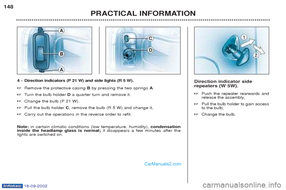
Direction indicator side repeaters (W 5W). ☞Push the repeater rearwards and
release the assembly,
☞ Pull the bulb holder to gain accessto the bulb,
☞ Change the bulb.
PRACTICAL INFORMATION
148
4 -
Direction indicators (P 21 W) and side lights (R 5 W).
☞ Remove the protective casing Bby pressing the two springs A.
☞ Turn the bulb holder Da quarter turn and remove it.
☞ Change the bulb (P 21 W).
☞ Pull the bulb holder C, remove the bulb (R 5 W) and change it,
☞ Carry out the operations in the reverse order to refit.
Note: in certain climatic conditions (low temperature, humidity), condensation
inside the headlamp glass is normal; it disappears a few minutes after the
lights are switched on.
Page 150 of 182
16-09-2002
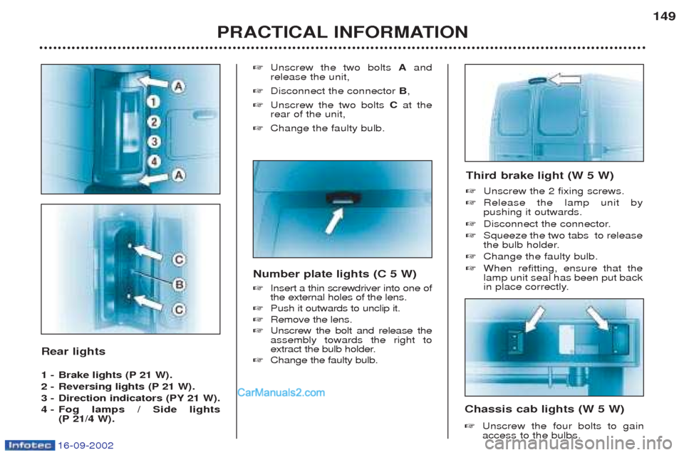
Rear lights
1 - Brake lights (P 21 W).
2 - Reversing lights (P 21 W).
3 - Direction indicators (PY 21 W).
4 - Fog lamps / Side lights
(P 21/4 W). ☞
Unscrew the two bolts Aand
release the unit,
☞ Disconnect the connector B,
☞ Unscrew the two bolts Cat the
rear of the unit,
☞ Change the faulty bulb.
PRACTICAL INFORMATION 149
Number plate lights (C 5 W) ☞ Insert a thin screwdriver into one of the external holes of the lens.
☞ Push it outwards to unclip it.
☞ Remove the lens.
☞ Unscrew the bolt and release theassembly towards the right to
extract the bulb holder.
☞ Change the faulty bulb.
Chassis cab lights (W 5 W) ☞Unscrew the four bolts to gain access to the bulbs.
Third brake light (W 5 W) ☞
Unscrew the 2 fixing screws.
☞ Release the lamp unit by pushing it outwards.
☞ Disconnect the connector.
☞ Squeeze the two tabs to release
the bulb holder.
☞ Change the faulty bulb.
☞ When refitting, ensure that thelamp unit seal has been put back
in place correctly.