PONTIAC FIERO 1988 Service Repair Manual
Manufacturer: PONTIAC, Model Year: 1988, Model line: FIERO, Model: PONTIAC FIERO 1988Pages: 1825, PDF Size: 99.44 MB
Page 1361 of 1825
AIR CONDITIONING: COMPRESSOR CONTROLS
C60, MANUAL
(Continued from previous page)
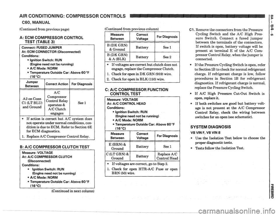
A: ECM COMPRESSOR CONTROL
TEST (TABLE
3)
Connect: FUSED JUMPER
At: ECM CONNECTOR (Disconnected)
Conditions:
0 Ignition Switch: RUN
(Engine need not be running]
AIC Mode: NORM
Temperature Outside Car: Above 60 OF
(16°C)
Jumper
Correct Action For Diagnosis
Between
engages
r If action is correct but A/C system does
not operate under normal conditions, con-
dition
is due to ECM. Refer to Section 6E
for ECM diagnostics.
1. Replace AIC Compressor Control Relay.
Corm
ILT BLU'
and Ground
B: AIC COMPRESSOR CLUTCH TEST
Measure: VOLTAGE
At:
AIC COMPRESSOR CLUTCH
(Disconnected)
Conditions: Ignition Switch: RUN
(Engine need not
be running)
r Ale Mode: NORM
Temperature Outside Car: Above
60 OF
116OC)
Compressor
Control Relay
operates
&
AIC Clutch (Continued from previous column)
1
See 1
Measure
I Between Correct I For
Diagnosis I I Vdtaas
/ (DK GRN' I Battery I See 1 & Ground
I BLz,",":' ( Battery I See 2
If voltages are correct hut clutch does not
engage, replace the Compressor Clutch.
I 1. Check for open in DK GRN (959) wire. 1
2. Check for open in BLK (150) wire.
C: AIC COMPRESSOR FUNCTION
CONTROL TEST
lgnition Switch: RUN
(Engine need not be running)
A/C Mode: NORM
open NTR-AIC Fuse or open
61. Remove the connectors from the Pressure
Cycling Switch and the
A/C High Pres-
sure Switch. Connect a fused jumper
between the ter
als of the connectors.
If switch is open, battery voltage will be
present at terminal
E of the AlC Com-
pressor Control Relay, when the jumper is
connected.
0 If the Pressure Cycling Switch is open, refer
to Section
1B to check for normal refrigerant
charge. If refrigerant charge is low, follow
procedures in Section
1B for refrigerant
diagnostics.
If refrigerant charge is normal,
replace the Pressure Cycling Switch.
@ If A/C High Pressure Cut-Out Switch is
open, replace it.
0 If both switches are good but battery volt-
age is not present at the
AIC Compressor
Control Relay, check the wiring between
switches for
an open (see schematic).
SYSTEM DIAGNOSIS
V8 VlN F, V8 VIN 8
@ Use the Isolation Test below to choose the
proper diagnostic tests.
Tests follow the Isolation Test.
(Continued in next co
Page 1362 of 1825
AIR CONDITIONING: COMPRESSOR
660, MANUAL
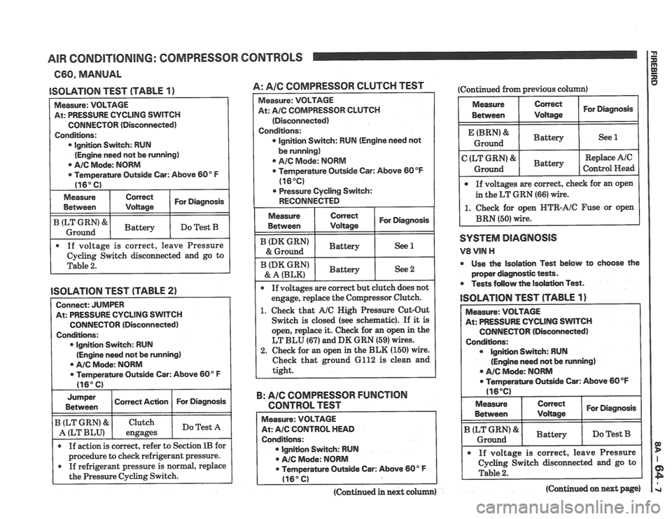
ISOLATION TEST (TABLE 1)
Measure: VOLTAGE
At: PRESSURE CYCLING
SWITCH
CONNECTOR (Disconnected)
Conditions: lgnition Switch: RUN
(Engine need not be running)
0 AIC Mode: NORM
Temperantre Outside Car: Above 60" F
(16" C)
Measure
Between Correct For Diagnosis /
I ILT Ground GRN'8rl Battery I Do Test B I
. If voltage is correct, leave Pressure
Cycling Switch disconnected and go to
Table
2.
ISOLATION TEST (TABLE 2)
Connect: JUMPER
At: PRESSURE CYCLING SWITCH
CONNECTOR (Disconnected)
Conditions: lgnition Switch: RUN
(Engine need not be running)
@ AIC Mode: NORM
0 Temperature Outside Car: Above 60" F
(16" C) I
Jumper I Correct Ac~on 1 For Diagnosis I I Between
If action is correct, refer to Section 1B for I
B (LT GRN) &
A (LT BLU)
I procedure to check refrigerant pressure. I
If refrigerant pressure is normal, replace
the Pressure Cycling Switch.
Clutch
engages
CONTROLS
Do Test A
A: Pale COMPRESSOR CLUTCH TEST
Measure: VOLTAGE
At:
A/C COMPRESSOR CLUTCH
(Disconnected)
Conditions:
0 Ignition Switch: RUN (Engine need not
be running)
0 AIC Mode: NORM
Temperature Outside Car: Above 60
OF
(16°C)
. Pressure Cycling Switch:
RECONNECTED
I
I ':"A':,",":' 1 ~attery I See 2 I
If voltages are correct but clutch does not
engage, replace the Compressor Clutch.
1. Check that AIC High Pressure Cut-Out
Switch is closed (see schematic). If
it is
open, replace it. Check for
an open in the
LT BLU
(67) and DK GRN (59) wires.
2. Check for an open in the BLK (150) wire.
Check that ground 6112 is clean and
tight.
B: AIC COMPRESSOR FUNCTION
CONTROL TEST
Measure: VOLTAGE
At: AIC CONTROL HEAD
Conditions: lgnition Switch: RUN
A/C Mode: NORM
0 Temperature Outside Car: Above 60" F
(16" C)
(Continued in next colum)
(Continued from previous column)
Measure Correct For Diagnosis
Between Voltage
Battery 1 See 1
Replace Ale
Control Head
If voltages are correct, check for an open
in the LT GRN
(66) wire.
1. Check for open HTR-AIC Fuse or open
BRN (50) wire.
SYSTEM DlAGlUOSlS
V8 VlN H
0 Use the isolation Test below to choose the
proper diagnostic tests.
Tests follow the Isolation Test.
lSOLATlOlU TEST (TABLE 1)
At: PRESSURE CYCLING SWITCH
CONNECTOR (Disconnected)
Ignition Switch: RUN
(Engine need not be running)
. A/C Mode: NORM
ramre Outside Car: Above 60 OF
Measure
I Between Correct I For Diagnosis I
Battery I Do Test B I I I
. If voltage is correct, leave Pressure
1 Cycling switch disconnected and go to I
(Continued on next page)
Page 1363 of 1825
AIR CONDITIONING: COMPRESSOR CONTROLS
C60, MANUAL
(Continued from previous page)
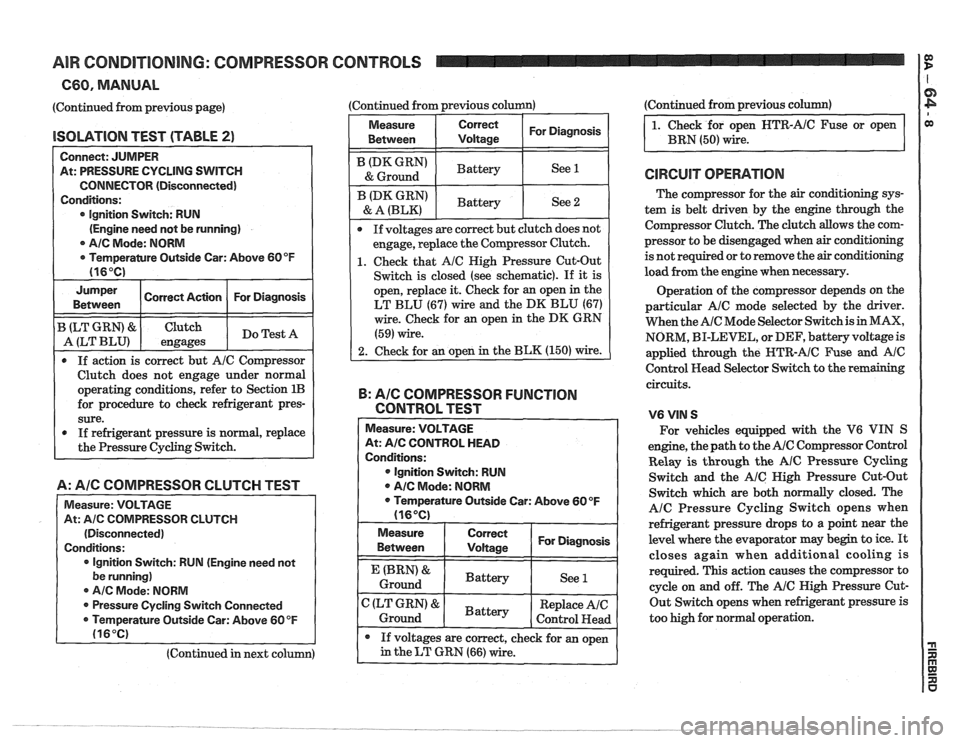
lSOLATlON TEST (TABLE 2)
Connect: JUMPER
At: PRESSURE CYCLING SWITCH
CONNECTOR (Disconnected)
Conditions:
lgnition Switch: RUN
(Engine need not be running)
0 AIC Mode: NORM
r Temperamre Outside Car: Above 60°F
Jumper I Correct Action I For Diagnosis I Between
B (LT GRN) & Clutch
A (LT BLU) engages Do
Test A
0 If action is correct but AIC Compressor
Clutch does not engage under normal
operating conditions, refer to Section
1B
for procedure to check refrigerant pres-
sure.
0 If refrigerant pressure is normal, replace
the Pressure Cycling Switch.
A: A/C COMPRESSOR CLUTCH TEST
Measure: VOLTAGE
At:
Ale COlVlPRESSOR CLUTCH
(Disconnected)
Conditions:
lgnition Switch:
RUN (Engine need not
be running)
0 A/C Mode: NORM
@ Pressure Cycling Switch Connected
0 Temperature Outside Car: Above 60 OF
(16°C)
(Continued in next column) (Continued
from previous column) (Continued
from previous column)
Measure
Between Correct I For Diagnosis I 1. Check for open HTR-AIC Fuse or open
BRN
(50) wire.
I (DK GRN' I Battery I See 1 I & Ground
@ If voltages are correct but clutch does not
engage, replace the Compressor Clutch.
1. Check that Ale Nigh Pressure Cut-Out
Switch is closed (see schematic).
If it is
open, replace it. Check for an open in the
LT BLU (67) wire and the DK BLU (67)
wire. Check for an open in the DK GRN
(59) wire.
2. Check for an open in the BLK (150) wire.
ID* GRN)
& A (BLK)
B: AIG COMPRESSOR FUNCTION
CONTROL TEST - -
Measure: VOLTAGE
At:
A/C CONTROL HEAD
Conditions:
@ Ignition Switch: RUN
@ AIC Mode: NORM
0 Temperature Outside Car: Above 60OF
(16OC)
Battery
Measure
Between
I ~~~~~~ I For Diagnosis I
See 2
(BRN' &
Ground
If voltages are correct, check for an open
in the LT GRN (66) wire.
C (LT GRN) &
Ground The
compressor for the
air conditioning sys-
tem is belt driven by the engine through the
Compressor Clutch. The clutch allows the com-
pressor to be disengaged when
air conditioning
is not required or to remove the
air conditioning
load from the engine when necessary.
-
Battery Operation
of the compressor depends on the
particular
AIC mode selected by the driver.
When the
AIC Mode Selector Switch is in MAX,
NORM, BI-LEVEL, or DEF, battery voltage is
applied through the
HTR-AIC Fuse and Ale
Control Head Selector Switch to the remaining
circuits.
See
1
Battery
V6VIN S
For vehicles equipped with the V6 VIN S
engine, the path to the
AIC Compressor Control
Relay
is through the AIC Pressure Cycling
Switch and the
AIC Nigh Pressure Cut-Out
Switch which are both normally closed. The
AlC Pressure Cycling Switch opens when
refrigerant pressure drops to a point near the
level where the evaporator may begin to ice.
It
closes again when additional cooling is
required. This action causes the compressor to
cycle on and off. The
AIC High Pressure Cut-
Out Switch opens when refrigerant pressure is
too high for normal operation.
Replace AIC
Control
Head
Page 1364 of 1825
AIR CONDITIONING: COMPRESSOR CONTROLS
660, MANUAL
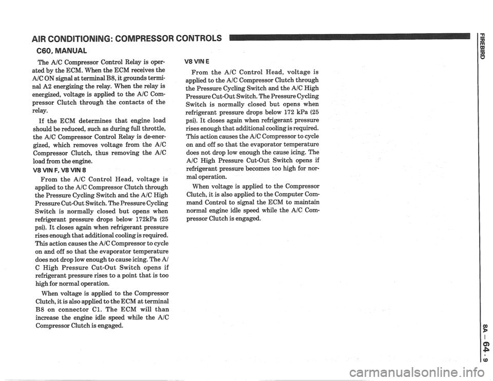
The A/C Compressor Control Relay is oper-
ated by the ECM. When the ECM receives the
A/C ON signal at terminal B8, it grounds termi-
nal A2 energizing the relay. When the relay is
energized, voltage is applied to the
AlC Com-
pressor Clutch through the contacts of the
relay.
If the ECM determines that engine load
should be reduced, such
as during full throttle,
the
A/C Compressor Control Relay is de-ener-
gized, which removes voltage from the Ale
Compressor Clutch, thus removing the Ale
load from the engine.
V8 VIN F, V8 VIN 8
From the A/C Control Read, voltage is
applied to the
A/C Compressor Clutch through
the Pressure Cycling Switch and the
A/C High
Pressure Cut-Out Switch. The Pressure
Cycling
Switch is normally closed but opens when
refrigerant pressure drops below
172kPa (25
psi).
It closes again when refrigerant pressure
rises enough that additional cooling is required.
This action causes the
A/C Compressor to cycle
on and off so that the evaporator temperature
does not drop low enough to cause icing. The
A/
C High Pressure Cut-Out Switch opens if
refrigerant pressure rises to a point that is too
high for normal operation.
When voltage is applied to the Compressor
Clutch, it is also applied to the ECM at terminal
B8 on connector Cl. The ECM will than
increase the engine idle speed while the
Ale
Compressor Clutch is engaged.
V8 VIM E
From the Ale Control Head, voltage is
applied to the
A/C Compressor Clutch through
the Pressure Cycling Switch and the
AIC High
Pressure Cut-Out Switch. The Pressure Cycling
Switch is normally closed but opens when
refrigerant pressure drops below 172
kPa (25
psi).
It closes again when refrigerant pressure
rises
enough that additional cooling is required.
This action causes the
AIC Compressor to cycle
on and off so that the evaporator temperature
does not drop low enough the cause icing. The
A/C High Pressure Cut-Out Switch opens if
refrigerant pressure becomes too high for nor-
mal operation.
When voltage is applied to the Compressor
Clutch, it is also applied to the Computer Com-
mand Control to signal the ECM to maintain
normal engine idle speed while the
Ale Com-
pressor Clutch is engaged.
Page 1365 of 1825
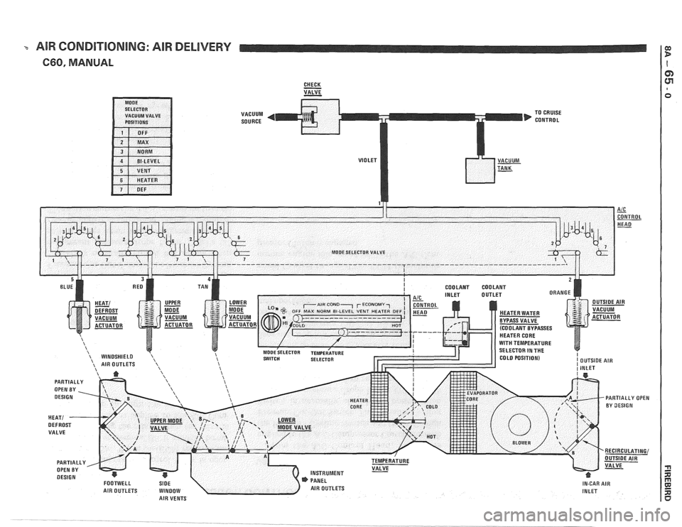
% AIR CONDITIONING: AIR DELIVERY
660, MANUAL
CHECK - VALVE -
VACUUM
SOURCE TO
CRUISE
CONTROL
Page 1366 of 1825
AIR CONDITIONING: AlR DELIVERY
660, MANUAL
TROUBLESHOOTING HINTS
Try the following checks before doing System
Diagnosis.
1. Cheek for manifold vacuum to the vacuum
tank at the BLACK hose from the engine and
at the VIOLET hose to the
A/C Control
Head.
2. Check the operation of the Temperature
Valve by moving the Temperature Selector
rapidly back and forth several times. Listen
for the valve to strike the stop at each end of
its travel.
If the sound indicates that the
valve is not fully closing or opening, check
the mechanical linkage between the valve
and the Temperature Selector.
3. Check that Heater Water Bypass Valve
operates when Temperature Selector is
moved to maximum cold position.
Go to the AlC System Check in 8A-62 for a
guide to normal operation and diagnostic ref-
erences for the entire
AIC System.
r Go to Systern Diagnosis to isolate air delivery
conditions.
SYSTEM DIAGNOSIS
Engine vvarm and running at idle.
If air flow does not come from the proper
outlets under one or more operating modes,
at least one of the air valves is not moving to
the proper position.
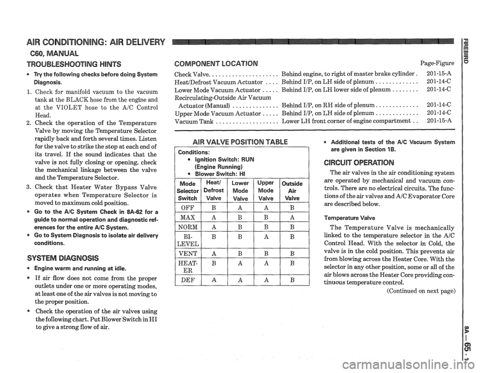
Check the operation of the air valves using
the following chart. Put Blower Switch in
HI
to give a strong flow of air.
COMPONENT LOGATlORl Page-Figure
Check Valve.
. . . . . . . . . . . . . . . . . . . . Behind engine, to right of master brake cylinder . 201-15-A
HeatIDefrost Vacuum Actuator . . . . Behind IIP, on LN side of plenum . . . . . . . . . . . . . 201-14-6
Lower Mode Vacuum Actuator
. . . . . Behind I/P, on LH lower side of plenum . . . . . . . . 201-14-C
Recirculating-Outside Air Vacuurn
Actuator (Manual) . . . . . . . . . . . . . . Behind IIP, on RH side of plenum. . . . . . . . . . . . . 201-14-6
Upper Mode Vacuum Actuator
. . . . . Behind I/P, on LN side of plenum . . . . . . . . . . . . . 201-14-6
Vacuum Tank
. . . . . . . . . . . . . . . . . . . Lower LIH front corner of engine compartment . . 201-15-A
AIR VALVE POSlTlON TABLE * Additional tests of the Ale Vacuum System
are given in Section
1 B.
GIWCUiT OPEMTIOIU
The air valves in the air conditioning system
are operated by mechanical and vacuum con-
trols. There are no electrical circuits. The func-
tions of the air valves and
A/C Evaporator Core
are described below.
Temperature Valve
The Temperature Valve is mechanically
linked to the temperature selector in the
AIC
Control Head. With the selector in Cold, the
valve is in the cold position. This prevents air
from blowing across the Heater Core. With the
selector in any other position, some or
all of the
air blows across the Heater Core providing con-
tinuous temperature control.
(Continued on next page)
Page 1367 of 1825
AIR CORIDI"F0NING: AIR DELIVERY
C60, MANUAL
(Continued from previous page)
AIC Evaporator Core
All air passing through the AIC Module
moves across the
A/C evaporator Core. When
the
AIC Compressor is on, the core is cooled and
removes moisture from the air.
Heater Water Bypass Valve
In most operating modes, engine coolant cir-
culates through the Heater Core to heat the
air
passing through the core. When the Tem-
perature Selector is moved to the maximum
cold position, the Heater Water Bypass Valve
is operated by mechanical linkage so that the
coolant does not flow through the Neater Core.
This allows maximum cooling of the
air.
Heat Defrost Valve
With the Mode Selector Switch in OFF, BI-
LEVEL or NEATER vacuum is applied to the
Heat Defrost Vacuum Actuator. The bellows
contract and the
HeatIDefrost Valve moves to
B position. Most of the air flows out of the
Footwell Air Outlets. In all other positions of
the Mode Selector Switch no vacuum is applied
to the Vacuum Actuator and the
Heater1
Defrost Valve remains in position A forcing
most of the
air out of the Windshield Air Out-
lets.
Upper and Lower Mode Valves
The two Mode Valves determine the amount
of
air flow to the Instrument Panel Air Outlets.
When the Mode Selector Switch is in MAX,
NORMAL or VENT, vacuum is applied to both
the Upper and Lower Mode Vacuum Actuators.
Both valves then move to position B and
all air
flows out the Instrument Panel Air Outlets. In
the BI-LEVEL mode, vacuum is applied only to
the Lower Mode Vacuum Actuator which
moves the Lower Mode Valve to position
B. The
Upper Mode Valve moves to position A. In
these positions some air flows out of the Instru-
ment Panel Air Outlets and the rest flows out
the
Footwell Air Outlet. IN HEATER, DEF
and OFF no vacuum is applied to either Vac-
uum Actuator and both
Valves move to posi-
tion A. All
air then flows to either the Footwell
Air Outlets or the Windshield Air Outlets
depending on the position of the
HeatIDefrost
Valve.
Outside Air Valve
When the AIC Mode Selector is moved to
MAX, vacuum is applied to the Outside Air
Vacuum Actuator. The bellows are drawn in
and the valve is moved to position A. Air from
inside the car is pulled into the
AIC Module.
In any other Mode Selector Switch position,
the Motor bellows are expanded and air is
drawn in from the outside.
Page 1368 of 1825

Page 1369 of 1825
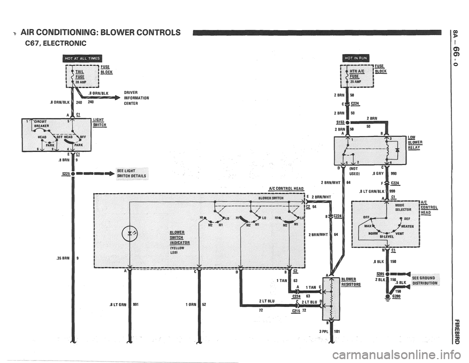
3 AIR CONDITIONING: BLOWER CONTROLS a, P
C67, ELECTRONlC I
DRIVER
INFORMATION
CENTER
Page 1370 of 1825
