Ram 3500 2020 Owner's Manual
Manufacturer: RAM, Model Year: 2020, Model line: 3500, Model: Ram 3500 2020Pages: 568
Page 351 of 568

IN CASE OF EMERGENCY349
(Continued)
SOS Call System Limitations
Vehicles sold in Mexico DO NOT have SOS Call
system capabilities. SOS or other emergency line operators in
Mexico may not answer or respond to SOS
system calls.
If the SOS Call system detects a malfunction,
any of the following may occur at the time the
malfunction is detected, and at the beginning of
each ignition cycle:
The overhead console light located between
the ASSIST and SOS buttons will continuously
be illuminated red.
The Device Screen will display the following
message: “Vehicle device requires service.
Please contact an authorized dealer.”
An In-Vehicle Audio message will state
“Vehicle device requires service. Please
contact an authorized dealer.”
Even if the SOS Call system is fully functional,
factors beyond FCA US LLC’s control may
prevent or stop the SOS Call system operation.
These include, but are not limited to, the
following factors:Delayed accessories mode is active.
The ignition is in the OFF position.
The vehicle’s electrical systems are not
intact.
The SOS Call system software and/or hard
-
ware are damaged during a crash.
The vehicle battery loses power or becomes
disconnected during a vehicle crash.
The SOS Call system is embedded into the
vehicle’s electrical system. Do not add
aftermarket electrical equipment to the
vehicle’s electrical system. This may
prevent your vehicle from sending a signal
to initiate an emergency call. To avoid inter -
ference that can cause the SOS Call system
to fail, never add aftermarket equipment
(e.g., two-way mobile radio, CB radio, data
recorder, etc.) to your vehicle’s electrical
system or modify the antennas on your
vehicle. IF YOUR VEHICLE LOSES BATTERY
POWER FOR ANY REASON (INCLUDING
DURING OR AFTER AN ACCIDENT), THE
UCONNECT FEATURES, APPS AND
SERVICES, AMONG OTHERS, WILL NOT
OPERATE.
Modifications to any part of the SOS Call
system could cause the air bag system to
fail when you need it. You could be injured
if the air bag system is not there to help
protect you.
WARNING! (Continued)
WARNING!
Ignoring the overhead console light could
mean you will not have SOS Call services. If
the overhead console light is illuminated,
have an authorized dealer service the SOS
Call system immediately.
The Occupant Restraint Control module
turns on the air bag Warning Light on the
instrument panel if a malfunction in any
part of the system is detected. If the Air Bag
Warning Light is illuminated, have an
authorized dealer service the Occupant
Restraint Control system immediately.
WARNING! (Continued)
6
20_DJD2_OM_EN_USC_t.book Page 349
Page 352 of 568

350IN CASE OF EMERGENCY
LTE (voice/data) or 4G (data) network and/or
Global Positioning Satellite signals are
unavailable or obstructed.
Equipment malfunction at the SOS operator
facility.
Operator error by the SOS operator.
LTE (voice/data) or 4G (data) network
congestion.
Weather.
Buildings, structures, geographic terrain, or
tunnels.
NOTE:
Your vehicle may be transmitting data as
authorized by the subscriber.
Never place anything on or near the vehicle’s
LTE (voice/data) or 4G (data) and GPS
antennas. You could prevent LTE (voice/
data) or 4G (data) and GPS signal reception,
which can prevent your vehicle from placing
an emergency call. An operable LTE (voice/
data) or 4G (data) network connection and a
GPS signal is required for the SOS Call
system to function properly.
GENERAL INFORMATION
The following regulatory statement applies to all
Radio Frequency (RF) devices equipped in this
vehicle:
This device complies with Part 15 of the FCC
Rules and with Innovation, Science and
Economic Development Canada license-exempt
RSS standard(s). Operation is subject to the
following two conditions:
1. This device may not cause harmful interference, and
2. This device must accept any interference received, including interference that may
cause undesired operation. Le présent appareil est conforme aux CNR
d`Innovation, Science and Economic
Development applicables aux appareils radio
exempts de licence. L'exploitation est autorisée
aux deux conditions suivantes:
1. l'appareil ne doit pas produire de
brouillage, et
2. l'utilisateur de l'appareil doit accepter tout brouillage radioélectrique subi, même si le
brouillage est susceptible d'en compro -
mettre le fonctionnement.
La operación de este equipo está sujeta a las
siguientes dos condiciones:
1. es posible que este equipo o dispositivo no cause interferencia perjudicial y
2. este equipo o dispositivo debe aceptar cualquier interferencia, incluyendo la que
pueda causar su operación no deseada.
NOTE:
Changes or modifications not expressly
approved by the party responsible for compli -
ance could void the user’s authority to operate
the equipment.
WARNING!
ALWAYS obey traffic laws and pay attention to
the road. ALWAYS drive safely with your hands
on the steering wheel. You have full
responsibility and assume all risks related to
the use of the features and applications in
this vehicle. Only use the features and
applications when it is safe to do so. Failure
to do so may result in an accident involving
serious injury or death.
20_DJD2_OM_EN_USC_t.book Page 350
Page 353 of 568

IN CASE OF EMERGENCY351
BULB REPLACEMENT
REPLACEMENT BULBS
All of the inside bulbs are brass or glass-wedge base. Aluminum base bulbs are not approved.
Interior Bulbs
Bulb Name Bulb Number
Overhead Console Lamps TS 212–9
Dome Lamp 7679
For lighted switches, see an authorized dealer for replacement instructions.
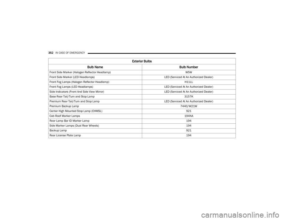
Exterior Bulbs
Bulb Name Bulb Number
Low Beam (Halogen Reflector Headlamp) H11LL
High Beam (Halogen Reflector Headlamp) 9005LL
Low & High Beam (LED Reflector Headlamp) LED (Serviced At An Authorized Dealer)
Low & High Beam (LED Projector Headlamp) LED (Serviced At An Authorized Dealer)
Turn Signal / Front Position (Halogen Reflector Headlamp) 7444NA
Turn Signal / Front Position (LED Headlamps) LED (Serviced At An Authorized Dealer)
6
20_DJD2_OM_EN_USC_t.book Page 351
Page 354 of 568

352IN CASE OF EMERGENCY
Front Side Marker (Halogen Reflector Headlamp) W5W
Front Side Marker (LED Headlamps) LED (Serviced At An Authorized Dealer)
Front Fog Lamps (Halogen Reflector Headlamp) H11LL
Front Fog Lamps (LED Headlamps) LED (Serviced At An Authorized Dealer)
Side Indicators (Front And Side View Mirror) LED (Serviced At An Authorized Dealer)
Base Rear Tail/Turn and Stop Lamp 3157K
Premium Rear Tail/Turn and Stop Lamp LED (Serviced At An Authorized Dealer)
Premium Backup Lamp 7440/W21W
Center High Mounted Stop Lamp (CHMSL) 921
Cab Roof Marker Lamps 194NA
Rear Lamp Bar ID Marker Lamp 194
Side Marker Lamps (Dual Rear Wheels) 194
Backup Lamp 921
Rear License Plate Lamp 194
Exterior Bulbs
Bulb Name Bulb Number
20_DJD2_OM_EN_USC_t.book Page 352
Page 355 of 568

IN CASE OF EMERGENCY353
REPLACING EXTERIOR BULBS
Base Quad: Low Beam Headlamp, High
Beam Headlamp, Front Park And Turn — If
Equipped
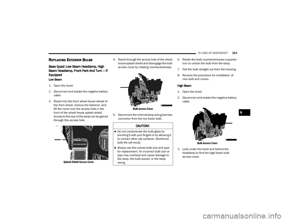
Low Beam
1. Open the hood.
2. Disconnect and isolate the negative battery
cable.
3. Reach into the front wheel house ahead of the front wheel, remove the fastener, and
lift the cover over the access hole in the
front of the wheel house splash shield.
Access to the rear of the lamp can be gained
through this access hole.
Splash Shield Access Cover
4. Reach through the access hole of the wheel
house splash shield and disengage the bulb
access cover by rotating counterclockwise.
Bulb Access Cover
5. Disconnect the internal lamp wiring harness connector from the low beam bulb. 6. Rotate the bulb counterclockwise a quarter
turn to unlock the bulb from the lamp.
7. Pull the bulb straight out from the housing.
8. Reverse the procedure for installation of new bulb and covers.
High Beam
1. Open the hood.
2. Disconnect and isolate the negative battery cable.
Bulb Access Cover
3. Look under the hood and behind the headlamp to find the high beam bulb
access cover.
CAUTION!
Do not contaminate the bulb glass by
touching it with your fingers or by allowing it
to contact other oily surfaces. Shortened
bulb life will result.
Always use the correct bulb size and type
for replacement. An incorrect bulb size or
type may overheat and cause damage to
the lamp, the bulb socket, or the lamp
wiring.
6
20_DJD2_OM_EN_USC_t.book Page 353
Page 356 of 568

354IN CASE OF EMERGENCY
4. Reach behind the headlamp and disengage
the access cover by rotating counter -
clockwise.
5. Disconnect the internal lamp wiring harness connector from the high beam bulb.
6. Rotate the bulb counterclockwise a quarter turn to unlock the bulb from the lamp.
7. Pull the bulb straight out from the housing.
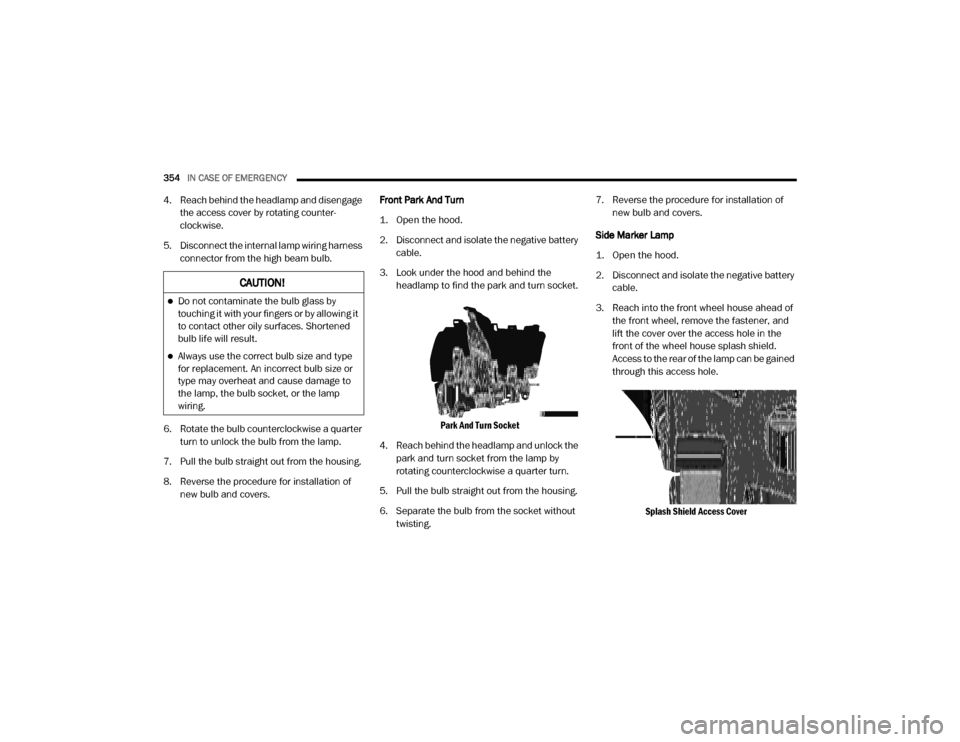
8. Reverse the procedure for installation of new bulb and covers. Front Park And Turn
1. Open the hood.
2. Disconnect and isolate the negative battery
cable.
3. Look under the hood and behind the headlamp to find the park and turn socket.
Park And Turn Socket
4. Reach behind the headlamp and unlock the park and turn socket from the lamp by
rotating counterclockwise a quarter turn.
5. Pull the bulb straight out from the housing.
6. Separate the bulb from the socket without twisting. 7. Reverse the procedure for installation of
new bulb and covers.
Side Marker Lamp
1. Open the hood.
2. Disconnect and isolate the negative battery cable.
3. Reach into the front wheel house ahead of the front wheel, remove the fastener, and
lift the cover over the access hole in the
front of the wheel house splash shield.
Access to the rear of the lamp can be gained
through this access hole.
Splash Shield Access Cover
CAUTION!
Do not contaminate the bulb glass by
touching it with your fingers or by allowing it
to contact other oily surfaces. Shortened
bulb life will result.
Always use the correct bulb size and type
for replacement. An incorrect bulb size or
type may overheat and cause damage to
the lamp, the bulb socket, or the lamp
wiring.
20_DJD2_OM_EN_USC_t.book Page 354
Page 357 of 568

IN CASE OF EMERGENCY355
4. Reach through the access hole of the wheel
house splash shield and disengage the side
marker socket by rotating counterclockwise
a quarter turn.
Side Marker Socket
5. Pull the socket and bulb straight out from the housing.
6. Separate the bulb from the socket without twisting.
7. Reverse the procedure for installation of new bulb and covers.
Fog Lamps — If Equipped
Please see an authorized dealer for service on
LED and Halogen front fog lamps. Halogen
1. Reach under and behind the front bumper
to access the back of the front fog lamp
housing.
2. Disconnect the fog lamp wiring harness connector from the fog lamp bulb.
3. Rotate the bulb counterclockwise a quarter turn to unlock the bulb from the housing.
Fog Lamp Bulb
4. Pull the bulb straight out from the housing.
Rear Tail/Stop, Turn Signal And Backup
Lamps
1. Remove the two screws and push pins that pass through the bed sheet metal.
Tail Lamp Locations
CAUTION!
Do not contaminate the bulb glass by
touching it with your fingers or by allowing it
to contact other oily surfaces. Shortened bulb
life will result.
1 — Tail Lamp
2 — Screws
3 — Fasteners
6
20_DJD2_OM_EN_USC_t.book Page 355
Page 358 of 568

356IN CASE OF EMERGENCY
2. Pull the outboard side of the lamp rearward
far enough to unsnap the two receptacles
on the outboard side of the lamp housing
from the two plastic snap post retainers in
the outer box side panel.
Tail Lamp Removed
3. Disconnect the wiring harness connectors from the bulb socket.
4. Rotate the bulb socket counterclockwise a quarter turn to unlock it from the housing.
5. Pull the bulb straight out of the socket. 6. Reverse the procedure to install the bulb
and housing.
Center High Mounted Stop Lamp (CHMSL)
With Cargo Lamp
1. Remove the two screws holding the housing/lens to the body as shown.
CHMSL Mounting Screw Locations
2. Separate the connector holding the housing and wiring harness to the body.
3. Turn the desired bulb socket a quarter turn and remove the socket and bulb from
housing. 4. Pull the desired bulb straight from the
socket.
CHMSL Bulb And Socket
Outside Bulbs: Cargo Lamps
Inside Bulb: Center High Mounted Stop
Lamp
5. Reverse the procedure for installation of bulbs and housing.
CAUTION!
Do not contaminate the bulb glass by
touching it with your fingers or by allowing it
to contact other oily surfaces. Shortened bulb
life will result.
CAUTION!
Do not contaminate the bulb glass by
touching it with your fingers or by allowing it
to contact other oily surfaces. Shortened bulb
life will result.
20_DJD2_OM_EN_USC_t.book Page 356
Page 359 of 568

IN CASE OF EMERGENCY357
Cab Top Clearance Lamps — If Equipped
1. Remove the screws from the top of the
lamp.
Removing Rear Screw From Clearance Lamp
2. Rotate the bulb socket a quarter turn and pull it from the lamp assembly.
Removing Bulb Socket From Clearance Lamp
3. Pull the bulb straight from it's socket and
replace.
Rear Lamp Bar ID Marker (Dual Rear
Wheels) — If Equipped
1. Loosen the two screws and the housing to gain access to the bulb sockets.
Screw Locations
2. Turn the socket a quarter turn counter -
clockwise to access the bulb.
3. Pull the bulb straight out from the socket.
4. Reverse the procedure for installation of the bulbs and housing.
Side Marker Lamps (Dual Rear Wheels) —
If Equipped
Side Marker Lamp Locations
1. Push rearward on the side marker lamp assembly.
2. Pull the entire assembly from the fender.
3. Turn the socket a quarter turn counter -
clockwise and remove from assembly to
access the bulb.
4. Pull the bulb straight out from socket.
5. Reverse the procedure for installation of the bulbs and housing.
6
20_DJD2_OM_EN_USC_t.book Page 357
Page 360 of 568

358IN CASE OF EMERGENCY
(Continued)
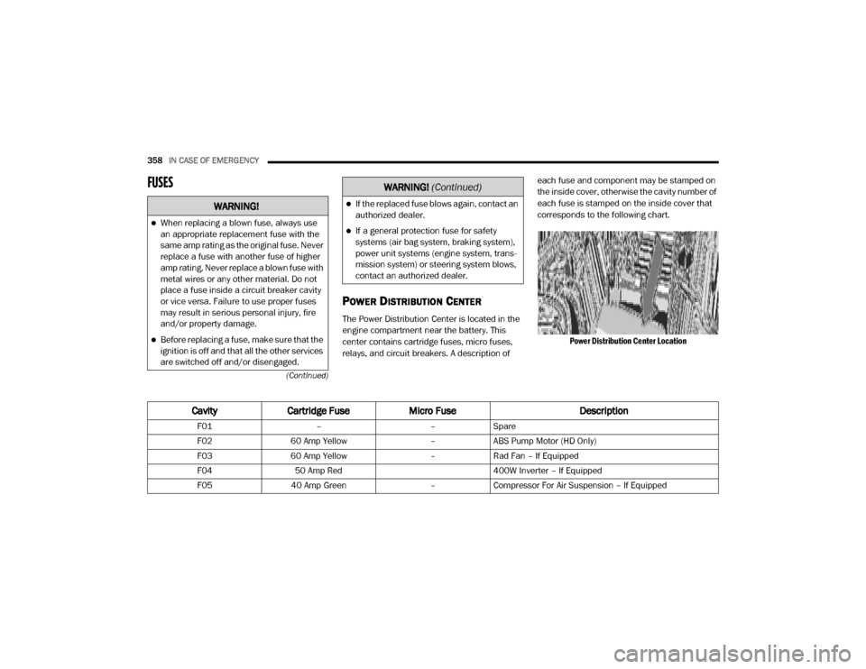
FUSES
POWER DISTRIBUTION CENTER
The Power Distribution Center is located in the
engine compartment near the battery. This
center contains cartridge fuses, micro fuses,
relays, and circuit breakers. A description of each fuse and component may be stamped on
the inside cover, otherwise the cavity number of
each fuse is stamped on the inside cover that
corresponds to the following chart.
Power Distribution Center Location
WARNING!
When replacing a blown fuse, always use
an appropriate replacement fuse with the
same amp rating as the original fuse. Never
replace a fuse with another fuse of higher
amp rating. Never replace a blown fuse with
metal wires or any other material. Do not
place a fuse inside a circuit breaker cavity
or vice versa. Failure to use proper fuses
may result in serious personal injury, fire
and/or property damage.
Before replacing a fuse, make sure that the
ignition is off and that all the other services
are switched off and/or disengaged.
If the replaced fuse blows again, contact an
authorized dealer.
If a general protection fuse for safety
systems (air bag system, braking system),
power unit systems (engine system, trans -
mission system) or steering system blows,
contact an authorized dealer.
WARNING! (Continued)
Cavity Cartridge Fuse Micro Fuse Description
F01––Spare
F02 60 Amp Yellow –ABS Pump Motor (HD Only)
F03 60 Amp Yellow –Rad Fan – If Equipped
F04 50 Amp Red 400W Inverter – If Equipped
F05 40 Amp Green –Compressor For Air Suspension – If Equipped
20_DJD2_OM_EN_USC_t.book Page 358