ignition RAM CHASSIS CAB 2021 User Guide
[x] Cancel search | Manufacturer: RAM, Model Year: 2021, Model line: CHASSIS CAB, Model: RAM CHASSIS CAB 2021Pages: 463, PDF Size: 21.5 MB
Page 26 of 463
24GETTING TO KNOW YOUR VEHICLE
2. Perform one of the following methods to
lock the vehicle:
Push the lock button on the interior
power door lock switch with the driver
and/or passenger door open.
Push the lock button on the exterior
Passive Entry Door Handle with a valid
key fob available in the same exterior
zone Ú page 26.
Push the lock button on the key fob.
3. If any doors are open, close them.
The Vehicle Security system will set when you
use the power door locks, or use the key fob to
lock the doors. After all the doors are locked
and closed, the vehicle security light, in the
instrument panel cluster, will flash rapidly for
about 16 seconds to indicate that the alarm is
being set. After the alarm is set, the vehicle
security light will flash at a slower rate to
indicate that the system is armed.
TO DISARM THE SYSTEM
The Vehicle Security system can be disarmed
using any of the following methods:
1. Push the unlock button on the key fob.
2. Grab the Passive Entry Door Handle with a valid key fob within 5 ft (1.5 m) of the
Passive Entry door handle (if equipped)
Úpage 26.
3. Cycle the ignition out of the OFF position.
The Vehicle Security system is designed to
protect your vehicle. However, you can create
conditions where the system will give you a false
alarm. If one of the previously described arming
sequences has occurred, the Vehicle Security
system will arm regardless of whether you are in
the vehicle or not. If you remain in the vehicle
and open a door, the alarm will sound. If this
occurs, disarm the Vehicle Security system.
If the Vehicle Security system is armed and the
battery becomes disconnected, the Vehicle
Security system will remain armed when the
battery is reconnected; the exterior lights will
flash, and the horn will sound. If this occurs,
disarm the Vehicle Security system.
REARMING OF THE SYSTEM
If something triggers the alarm, and no action is
taken to disarm it, the Vehicle Security system
will turn the horn off after 29 seconds,
five seconds between cycles, and up to eight
cycles if the trigger remains active. The Vehicle
Security system will then rearm itself.
SECURITY SYSTEM MANUAL OVERRIDE
The Vehicle Security system will not arm if you
lock the doors using the manual door lock.
DOORS
MANUAL DOOR LOCKS
The power door locks can be manually locked
from inside the vehicle by using the door lock
knob. To lock each door, push the door lock
knob on each door trim panel downward.
To unlock the front doors, pull the inside door
handle to the first detent. To unlock the rear
doors, pull the door lock knob on the door trim
panel upward. If the lock knob is down when the
door is closed, the door will lock. Therefore,
make sure the key fob is not inside the vehicle
before closing the door.
21_DPF_OM_EN_USC_t.book Page 24
Page 27 of 463
GETTING TO KNOW YOUR VEHICLE25
(Continued)
Door Lock Knob
POWER DOOR LOCKS — IF EQUIPPED
The power door lock switches are located on
each front door panel. Push the switch to lock or
unlock the doors.
Power Door Lock Switches
The driver’s door will unlock automatically if the
keys are found inside the vehicle when the door
lock button on the front door panel is used to
lock the door. This will occur for two attempts.
Upon the third attempt, the doors will lock even
if the key is inside.
WARNING!
Do not leave children or animals inside
parked vehicles in hot weather. Interior
heat build-up may cause serious injury or
death.
For personal security and safety in the
event of an collision, lock the vehicle doors
as you drive as well as when you park and
leave the vehicle.
Before exiting a vehicle, always shift the
automatic transmission into PARK, apply
the parking brake, turn the vehicle OFF,
remove the key fobs from vehicle, and lock
all doors. and lock your vehicle.
Never leave children alone in a vehicle,
or with access to an unlocked vehicle.
Leaving children in a vehicle unattended is
dangerous for a number of reasons. A child
or others could be seriously or fatally injured.
Children should be warned not to touch the
parking brake, brake pedal or the gear
selector.
Allowing children to be in a vehicle unat -
tended is dangerous for a number of
reasons. A child or others could be seriously
or fatally injured. Children should be
warned not to touch the parking brake,
brake pedal or the gear selector.
Do not leave the key fob in or near the
vehicle, or in a location accessible to chil-
dren, and do not leave the ignition of a
vehicle equipped with Keyless Enter-N-Go
in the ACC or ON/RUN mode. A child could
operate power windows, other controls, or
move the vehicle.
WARNING! (Continued)
2
21_DPF_OM_EN_USC_t.book Page 25
Page 28 of 463
26GETTING TO KNOW YOUR VEHICLE
NOTE:
If the key fob is located next to a mobile phone,
laptop, or other electronic device, the wireless
signal may get blocked, and the driver’s door
may not unlock automatically.
If the door lock switch is pushed while the
ignition is in ACC or ON/RUN and the driver's
door is open, the doors will not lock.
KEYLESS ENTER-N-GO — PASSIVE
E
NTRY (IF EQUIPPED)
The Passive Entry system is an enhancement to
the vehicle’s Remote Keyless Entry system and a
feature of Keyless Enter-N-Go. This feature allows
you to lock and unlock the vehicle’s door(s)
without having to push the key fob lock or unlock
buttons.
NOTE:
Passive Entry may be programmed on/off
within Uconnect Settings Ú page 228.
If wearing gloves or if it has been raining/
snowing on the Passive Entry door handle,
the unlock sensitivity can be affected,
resulting in a slower response time.
If the vehicle is unlocked by Passive Entry
and no door is opened within 60 seconds, the
vehicle will re-lock and if equipped will arm
the security alarm.
The Vehicle Security system can be armed/
disarmed by pushing the Passive Entry key
fob lock/unlock buttons (if equipped).
The key fob may not be able to be detected by
the vehicle Passive Entry system if it is located
next to a mobile phone, laptop or other elec -
tronic device; these devices may block the key
fob's wireless signal and prevent the Passive
Entry door handle from locking/unlocking the
vehicle.
To Unlock From The Driver or Passenger Side:
With a valid Passive Entry key fob within 5 ft
(1.5 m) of the door handle, grab the handle to
unlock the vehicle. Grabbing the driver’s door
handle will unlock the driver door automatically.
Grabbing the passenger door handle will unlock
all doors automatically. The interior door panel
lock knob will raise when the door is unlocked.
Grab The Door Handle To Unlock
NOTE:
If “Unlock All Doors 1st Press” is
programmed all doors will unlock when you
grab hold of the front driver’s door handle.
You can select between “Unlock Driver Door
1st Press” and “Unlock All Doors 1st Press”
within Uconnect Settings Ú page 228.
All doors will unlock when the front
passenger door handle is grabbed regardless
of the driver’s door unlock preference
setting.
21_DPF_OM_EN_USC_t.book Page 26
Page 29 of 463
GETTING TO KNOW YOUR VEHICLE27
Preventing Inadvertent Locking Of Passive Entry
Key Fob In Vehicle:
To minimize the possibility of unintentionally
locking a Passive Entry key fob inside your
vehicle, the Passive Entry system is equipped
with an automatic door unlock feature which
will function if the ignition switch is in the OFF
position.
If one of the vehicle doors is open and the door
panel switch is used to lock the vehicle, once all
open doors have been closed the vehicle checks
the inside and outside of the vehicle for any valid
Passive Entry key fobs. If one of the vehicle's
Passive Entry key fobs is detected inside the
vehicle, and no other valid Passive Entry key fobs
are detected outside the vehicle, the Passive
Entry system automatically unlocks all vehicle
doors and chirps the horn three times (on the
third attempt ALL doors will lock and the Passive
Entry key fob can be locked in the vehicle).
To Lock The Vehicle’s Doors:
With one of the vehicle’s Passive Entry key fobs
within 5 ft (1.5 m) of the driver or passenger
front door handles, push the door handle lock
button to lock all doors.
Push The Door Handle Button To Lock
Do NOT grab the door handle when pushing the
door handle lock button. This could unlock the
door(s).
Do NOT Grab The Door Handle When Locking
NOTE:
After pushing the door handle lock button,
you must wait two seconds before you can
lock or unlock the doors, using either Passive
Entry door handle. This is done to allow you to
check if the vehicle is locked by pulling the
door handle, without the vehicle unlocking.
The Passive Entry system depends on a key
fob that is not fully discharged of its coin
battery capacity.
When the key fob battery is low, the instrument
cluster will display a message indicating that
the key fob battery is low
Ú
page 15.
2
21_DPF_OM_EN_USC_t.book Page 27
Page 34 of 463
32GETTING TO KNOW YOUR VEHICLE
DRIVER MEMORY SETTINGS — IF EQUIPPED
This feature allows the driver to save up to
two different memory profiles for easy recall
through a memory switch. Each memory profile
saves desired position settings for the following
features:
Driver seat position
Easy Entry/Exit seat operation (on/off)
(if equipped)
Side mirrors
Adjustable pedals (if equipped)
A set of desired radio station presets
NOTE:
If equipped with power convex mirrors, these
mirror positions will not set as part of a
memory profile.
Your vehicle is equipped with two key fobs,
one key fob can be linked to memory position
1 and the other key fob can be linked to
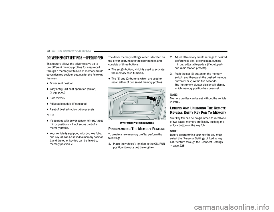
memory position 2. The driver memory settings switch is located on
the driver door, next to the door handle, and
consists of three buttons:
The set (S) button, which is used to activate
the memory save function.
The (1) and (2) buttons which are used to
recall either of two saved memory profiles.
Driver Memory Settings Buttons
PROGRAMMING THE MEMORY FEATURE
To create a new memory profile, perform the
following:
1. Place the vehicle’s ignition in the ON/RUN position (do not start the engine).
2. Adjust all memory profile settings to desired
preferences (i.e., driver’s seat, outside
mirrors, adjustable pedals (if equipped),
and radio station presets).
3. Push the set (S) button on the memory switch, and then push the desired memory
button (1 or 2) within five seconds.
The instrument cluster display will display
which memory position has been set.
NOTE:
Memory profiles can be set without the vehicle
in PARK.
LINKING AND UNLINKING THE REMOTE
K
EYLESS ENTRY KEY FOB TO MEMORY
Your key fob can be programmed to recall one
of two saved memory profiles by pushing the
unlock button on the key fob.
NOTE:
Before programming your key fob you must
select the “Personal Settings Linked to Key
Fob” feature through the Uconnect Settings
Ú page 228.
21_DPF_OM_EN_USC_t.book Page 32
Page 35 of 463

GETTING TO KNOW YOUR VEHICLE33
To program your key fob, perform the following:
1. Place the vehicle’s ignition in the OFF
position.
2. Select a desired memory profile 1 or 2.
3. Once the profile has been recalled, push and release the set (S) button on the
memory switch.
4. Push and release button (1) or (2) accordingly. “Memory Profile Set” (1 or 2)
will display in the instrument cluster.
5. Push and release the lock button on the key fob within 10 seconds.
NOTE:
Your key fob can be unlinked from your memory
settings by pushing the set (S) button, and
within 10 seconds, pushing the unlock button
on the key fob.MEMORY POSITION RECALL
NOTE:
The vehicle speed must be lower than 5 mph
(8 km/h) to recall memory positions. If a recall
is attempted when the vehicle speed is greater
than 5 mph (8 km/h), a message will be
displayed in the instrument cluster display.
To recall the memory settings for driver one or
two, push the desired memory button number
(1 or 2) or the unlock button on the key fob
linked to the desired memory position.
A recall can be cancelled by pushing any of the
memory buttons during a recall (S, 1, or 2). When
a recall is canceled, the driver's seat and the
adjustable pedals (if equipped) stop moving.
A delay of one second will occur before another
recall can be selected.
SEATS
Seats are a part of the Occupant Restraint
System of the vehicle.
WARNING!
It is dangerous to ride in a cargo area,
inside or outside of a vehicle. In a collision,
people riding in these areas are more likely
to be seriously injured or killed.
Do not allow people to ride in any area of
your vehicle that is not equipped with seats
and seat belts. In a collision, people riding
in these areas are more likely to be seri -
ously injured or killed.
Be sure everyone in your vehicle is in a seat
and using a seat belt properly.
2
21_DPF_OM_EN_USC_t.book Page 33
Page 38 of 463

36GETTING TO KNOW YOUR VEHICLE
(Continued)
Power Lumbar — If Equipped
Vehicles equipped with power driver or
passenger seats may also be equipped with
power lumbar. The power lumbar switch is
located on the outboard side of the power seat.
Push the switch forward to increase the lumbar
support. Push the switch rearward to decrease
the lumbar support.
Lumbar Control Switch
Easy Entry/Exit Seat
This feature provides automatic driver’s seat
positioning to enhance driver mobility when
entering and exiting the vehicle. The distance the driver’s seat moves depends
on where you have the driver’s seat positioned
when you remove the key fob from the ignition.
When you place the ignition in the OFF posi
-
tion, the driver’s seat will move about
2.4 inches (60 mm) rearward if the driver’s seat position is greater than or equal to
2.7 inches (67.7 mm) forward of the rear stop. The seat will return to its previously set
position when you place the ignition into the
ACC or RUN position.
When you place the ignition in the OFF position,
the driver’s seat will move to a position
0.3 inches (7.7 mm) forward of the rear stop if
the driver’s seat position is between 0.9 inches
and 2.7 inches (22.7 mm and 67.7 mm) forward of the rear stop. The seat will return to its previ-
ously set position when you place the ignition to
the ACC or RUN position.
The Easy Entry/Exit feature is disabled when
the driver’s seat position is less than
0.9 inches (22.7 mm) forward of the rear stop.
At this position, there is no benefit to the driver
by moving the seat for Easy Exit or Easy Entry.
When enabled in Uconnect Settings, Easy Entry
and Easy Exit positions are stored in each
memory setting profile Ú
page 32.
NOTE:
The Easy Entry/Exit feature is enabled or
disabled through the programmable features in
the Uconnect system Ú page 228.
HEATED SEATS — IF EQUIPPED
On some models, the front and rear seats may
be equipped with heaters located in the seat
cushions and seat backs.
WARNING!
Persons who are unable to feel pain to the
skin because of advanced age, chronic
illness, diabetes, spinal cord injury, medica -
tion, alcohol use, exhaustion or other phys -
ical condition must exercise care when
using the seat heater. It may cause burns
even at low temperatures, especially if
used for long periods of time.
21_DPF_OM_EN_USC_t.book Page 36
Page 42 of 463
40GETTING TO KNOW YOUR VEHICLE
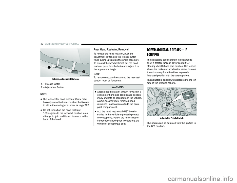
Release/Adjustment Buttons
NOTE:
The rear center head restraint (Crew Cab)
has only one adjustment position that is used
to aid in the routing of a tether Ú page 292.
Do not reposition the head restraint
180 degrees to the incorrect position in an
attempt to gain additional clearance to the
back of the head.
Rear Head Restraint Removal
To remove the head restraint, push the
adjustment button and the release button
while pulling upward on the whole assembly.
To reinstall the head restraint, put the head
restraint posts into the holes and adjust it to
the appropriate height.
NOTE:
To remove outboard restraints, the rear seat
bottom must be folded up.
DRIVER ADJUSTABLE PEDALS — IF
EQUIPPED
The adjustable pedals system is designed to
allow a greater range of driver comfort for
steering wheel tilt and seat position. This feature
allows the brake and accelerator pedals to move
toward or away from the driver to provide
improved position with the steering wheel.
The adjustable pedal switch is located to the left
side of the steering column.
Adjustable Pedals Switch
The pedals can be adjusted with the ignition in
the OFF position.
1 — Release Button
2 — Adjustment Button
WARNING!
A loose head restraint thrown forward in a
collision or hard stop could cause serious
injury or death to occupants of the vehicle.
Always securely stow removed head
restraints in a location outside the occu -
pant compartment.
ALL the head restraints MUST be rein -
stalled in the vehicle to properly protect
the occupants. Follow the re-installation
instructions above prior to operating the
vehicle or occupying a seat.
21_DPF_OM_EN_USC_t.book Page 40
Page 49 of 463
GETTING TO KNOW YOUR VEHICLE47
UNIVERSAL GARAGE DOOR OPENER
(HOMELINK®) — IF EQUIPPED
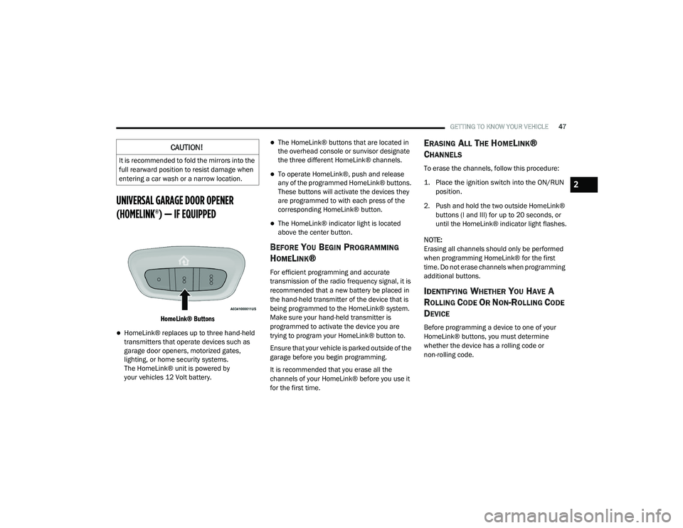
HomeLink® Buttons
HomeLink® replaces up to three hand-held
transmitters that operate devices such as
garage door openers, motorized gates,
lighting, or home security systems.
The HomeLink® unit is powered by
your vehicles 12 Volt battery.
The HomeLink® buttons that are located in
the overhead console or sunvisor designate
the three different HomeLink® channels.
To operate HomeLink®, push and release
any of the programmed HomeLink® buttons.
These buttons will activate the devices they
are programmed to with each press of the
corresponding HomeLink® button.
The HomeLink® indicator light is located
above the center button.
BEFORE YOU BEGIN PROGRAMMING
H
OMELINK®
For efficient programming and accurate
transmission of the radio frequency signal, it is
recommended that a new battery be placed in
the hand-held transmitter of the device that is
being programmed to the HomeLink® system.
Make sure your hand-held transmitter is
programmed to activate the device you are
trying to program your HomeLink® button to.
Ensure that your vehicle is parked outside of the
garage before you begin programming.
It is recommended that you erase all the
channels of your HomeLink® before you use it
for the first time.
ERASING ALL THE HOMELINK®
C
HANNELS
To erase the channels, follow this procedure:
1. Place the ignition switch into the ON/RUN
position.
2. Push and hold the two outside HomeLink® buttons (I and III) for up to 20 seconds, or
until the HomeLink® indicator light flashes.
NOTE:
Erasing all channels should only be performed
when programming HomeLink® for the first
time. Do not erase channels when programming
additional buttons.
IDENTIFYING WHETHER YOU HAVE A
R
OLLING CODE OR NON-ROLLING CODE
D
EVICE
Before programming a device to one of your
HomeLink® buttons, you must determine
whether the device has a rolling code or
non-rolling code.
CAUTION!
It is recommended to fold the mirrors into the
full rearward position to resist damage when
entering a car wash or a narrow location.
2
21_DPF_OM_EN_USC_t.book Page 47
Page 50 of 463

48GETTING TO KNOW YOUR VEHICLE
Rolling Code Devices
To determine if your device has a rolling code, a
good indicator is its manufacturing date.
Typically, devices manufactured after 1995
have rolling codes. A device with a rolling code
will also have a “LEARN” or “TRAIN” button
located where the antenna is attached to the
device. The button may not be immediately
visible when looking at the device. The name
and color of the button may vary slightly by
manufacturer.
NOTE:
The “LEARN” or “TRAIN” button is not the button
you normally use to operate the device.
Non-rolling Code Devices
Most devices manufactured before 1995 will
not have a rolling code. These devices will also
not have a “LEARN” or “TRAIN” button.PROGRAMMING HOMELINK® TO A
G
ARAGE DOOR OPENER
To program any of the HomeLink® buttons to
activate your garage door opener motor, follow
the steps below:
NOTE:
All HomeLink® buttons are programmed using
this procedure. You do not need to erase all
channels when programming additional
buttons.
1. Place the ignition switch into the ON/RUN
position.
2. Place the garage door opener transmitter 1 to 3 inches (3 to 8 cm) away from the
HomeLink® button you wish to program,
while keeping the HomeLink® indicator
light in view.
3. Push and hold the HomeLink® button you want to program while you push and hold
the garage door opener transmitter button
you are trying to replicate.
4. Continue to hold both buttons and observe the
HomeLink® indicator light. The HomeLink®
indicator light will flash slowly and then rapidly.
Once this happens, release both buttons.
NOTE:
Make sure the garage door opener motor is
plugged in before moving on to the rolling
code/non-rolling code final steps.
Rolling Code Garage Door Opener Final Steps
NOTE:
You have 30 seconds in which to initiate rolling
code final step 2, after completing rolling code
final step 1.
1. At the garage door opener motor (in the garage), locate the “LEARN” or “TRAIN”
button. This can usually be found where the
hanging antenna wire is attached to the
garage door opener motor. Firmly push and
release the “LEARN” or “TRAIN” button.
21_DPF_OM_EN_USC_t.book Page 48