RAM PROMASTER 2023 Owners Manual
Manufacturer: RAM, Model Year: 2023, Model line: PROMASTER, Model: RAM PROMASTER 2023Pages: 296, PDF Size: 12.31 MB
Page 241 of 296

SERVICING AND MAINTENANCE239
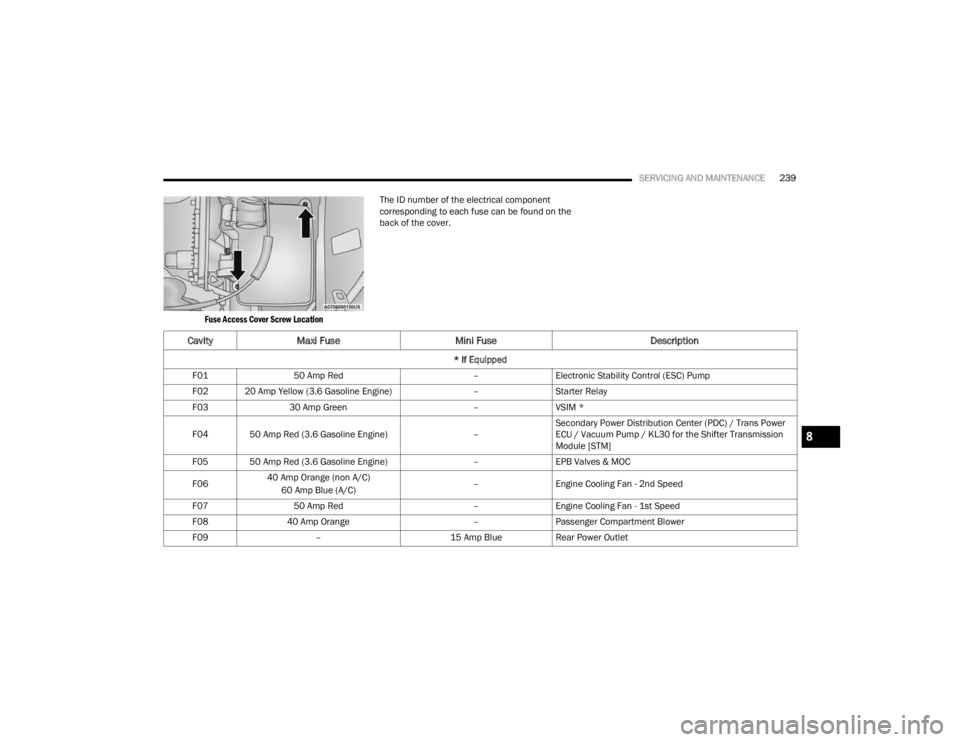
Fuse Access Cover Screw Location
The ID number of the electrical component
corresponding to each fuse can be found on the
back of the cover.
Cavity
Maxi Fuse Mini Fuse Description
* If Equipped
F01 50 Amp Red –Electronic Stability Control (ESC) Pump
F02 20 Amp Yellow (3.6 Gasoline Engine) –Starter Relay
F03 30 Amp Green –VSIM *
F04 50 Amp Red (3.6 Gasoline Engine) –Secondary Power Distribution Center (PDC) / Trans Power
ECU / Vacuum Pump / KL30 for the Shifter Transmission
Module [STM]
F05 50 Amp Red (3.6 Gasoline Engine) –EPB Valves & MOC
F06 40 Amp Orange (non A/C)
60 Amp Blue (A/C) –
Engine Cooling Fan - 2nd Speed
F07 50 Amp Red –Engine Cooling Fan - 1st Speed
F08 40 Amp Orange –Passenger Compartment Blower
F09 – 15 Amp BlueRear Power Outlet
8
23_VF_OM_EN_USC_t.book Page 239
Page 242 of 296

240SERVICING AND MAINTENANCE
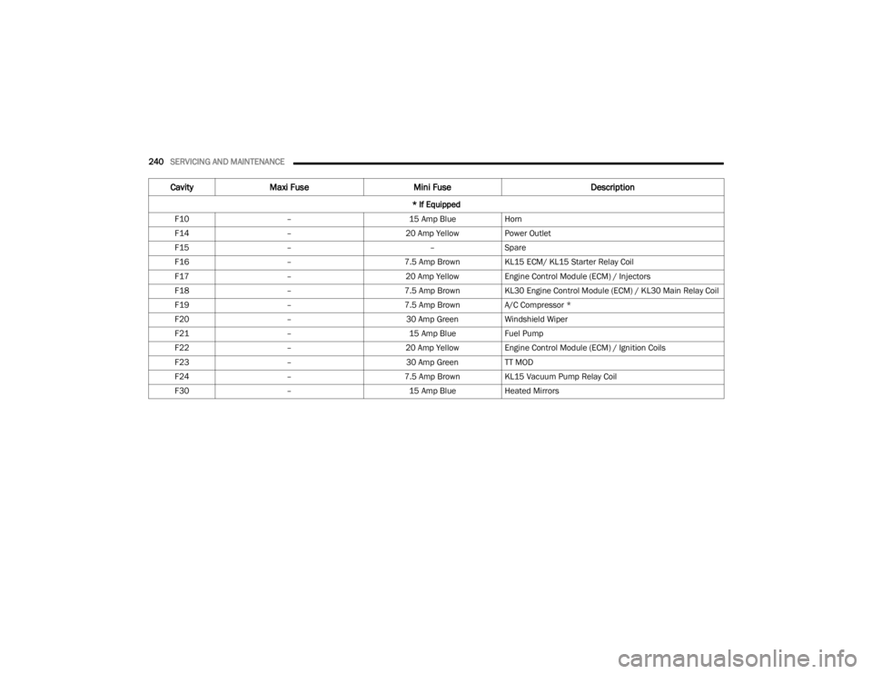
F10 – 15 Amp BlueHorn
F14 – 20 Amp YellowPower Outlet
F15 – –Spare
F16 – 7.5 Amp BrownKL15 ECM/ KL15 Starter Relay Coil
F17 – 20 Amp YellowEngine Control Module (ECM) / Injectors
F18 – 7.5 Amp BrownKL30 Engine Control Module (ECM) / KL30 Main Relay Coil
F19 – 7.5 Amp BrownA/C Compressor *
F20 – 30 Amp GreenWindshield Wiper
F21 – 15 Amp BlueFuel Pump
F22 – 20 Amp YellowEngine Control Module (ECM) / Ignition Coils
F23 – 30 Amp GreenTT MOD
F24 – 7.5 Amp BrownKL15 Vacuum Pump Relay Coil
F30 – 15 Amp BlueHeated Mirrors
CavityMaxi Fuse Mini Fuse Description
* If Equipped
23_VF_OM_EN_USC_t.book Page 240
Page 243 of 296

SERVICING AND MAINTENANCE241
Front PDC Additional Fuses
The additional fuse box is located inside the front
PDC Box.
Front Power Distribution Center Additional Fuses
CavityMini Fuse Description
* If Equipped
F61 30 Amp Green Vacuum Pump
F62 30 Amp Green Transmission Power RELE
F65 15 Amp Blue Trailer Tow Mod
F66 15 Amp Blue Trailer Tow Mod
F67 5 Amp Beige Rear Roll Up Door *
F68 5 Amp Beige Shifter Transmission Module (STM)
8
23_VF_OM_EN_USC_t.book Page 241
Page 244 of 296

242SERVICING AND MAINTENANCE
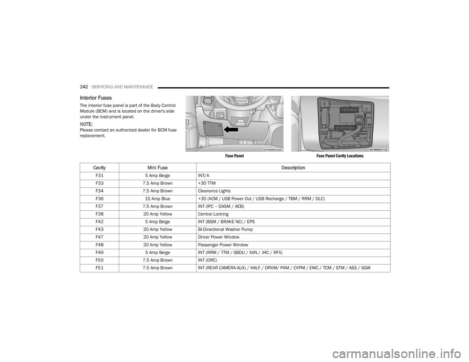
Interior Fuses
The interior fuse panel is part of the Body Control
Module (BCM) and is located on the driver's side
under the instrument panel.
NOTE:Please contact an authorized dealer for BCM fuse
replacement.
Fuse PanelFuse Panel Cavity Locations
CavityMini Fuse Description
F315 Amp Beige INT/A
F33 7.5 Amp Brown +30 TTM
F34 7.5 Amp Brown Clearance Lights
F36 15 Amp Blue +30 (ACM / USB Power Out / USB Recharge / TBM / RRM / DLC)
F37 7.5 Amp Brown INT (IPC – DASM / AEB)
F38 20 Amp Yellow Central Locking
F42 5 Amp Beige INT (BSM / BRAKE NC) / EPS
F43 20 Amp Yellow Bi-Directional Washer Pump
F47 20 Amp Yellow Driver Power Window
F48 20 Amp Yellow Passenger Power Window
F49 5 Amp Beige INT (RRM / TTM / SBDU / XAN / JHC / RFX)
F50 7.5 Amp Brown INT (ORC)
F51 7.5 Amp Brown INT (REAR CAMERA-AUX) / HALF / DRVM/ PAM / CVPM / EMC / TCM / STM / ASS / SGW
23_VF_OM_EN_USC_t.book Page 242
Page 245 of 296

SERVICING AND MAINTENANCE243
Right Central Pillar Fuses
The right central pillar fuse panel is located on the
interior side at the base of the passenger side
B-pillar.
Fuse Panel LocationFuse Panel
F53
7.5 Amp Brown +30 (IPC) + Keyless – GO / Passive Entry / Brake NO / EPB SW
F94 15 Amp Blue Not Used
CavityMini Fuse Description
CavityMini Fuse Description
* If Equipped
F81 7.5 Amp BrownSeat Heater
F82 30 Amp GreenInverter Power Outlet
F83 20 Amp YellowRear Left Windows Heater
F84 20 Amp YellowRear Right Windows Heater
F86 20 Amp YellowAuxiliary Switch (From Battery) *
F87 20 Amp YellowAuxiliary Switch (From Ignition) *8
23_VF_OM_EN_USC_t.book Page 243
Page 246 of 296

244SERVICING AND MAINTENANCE
BULB REPLACEMENT
Replacement Bulbs, Names, And Part Numbers
In the instance a bulb needs to be replaced, this section includes bulb description and replacement part numbers.
NOTE:See an authorized dealer for LED bulb replacement.
Interior Bulbs
Bulb Name Bulb Number
Dome Lamp C5W
Courtesy Lamp FF500
Cargo Lamp C5W
Exterior Bulbs
Bulb Name Bulb Number
Low Beam Headlamp (Halogen – If Equipped) H11LL
High Beam Headlamp (Halogen – If Equipped) 9005LL
Low Beam Headlamp LED
High Beam Headlamp LED
Front Park/Turn Signal Lamps (Halogen – If Equipped) T20
Daytime Running Lamps (Halogen – If Equipped) T20
Front Park/Turn Signal/Daytime Running Lamps LED
Front Side Marker Lamps (Halogen – If Equipped) W3W
Front Side Marker Lamps LED
23_VF_OM_EN_USC_t.book Page 244
Page 247 of 296

SERVICING AND MAINTENANCE245
Front Fog Lamps (Halogen – If Equipped) PSX24W
Front Fog Lamps LED
Rear Tail/Stop Lamps W21/5W
Rear Turn Signal Lamps WY21W
Rear Backup Lamps 921
Rear Side Marker Lamps W5W
License Plate Lamps (Halogen – If Equipped) C5W
License Plate Lamps (RR Roll Up Door – If Equipped) LED
Front Roof Lamps WY5W
Rear Roof Lamps W3W
NOTE:Numbers refer to commercial bulb types that can be purchased from an authorized dealer. If a bulb needs to be replaced, visit an authorized dealer.
Exterior Bulbs
Bulb Name Bulb Number
8
23_VF_OM_EN_USC_t.book Page 245
Page 248 of 296

246SERVICING AND MAINTENANCE
Replacing Exterior Bulbs
HEADLAMPS LOW BEAM AND HIGH BEAM
See the following steps to replace:
1. Disconnect the negative battery terminal.
2. Remove the headlamp retaining screws.
3. Remove the headlamp assembly from the
vehicle (by moving the headlamp to release
the lower slides from the headlamp mounting
on the vehicle).
4. Disconnect the headlamp harness electrical connector.
5. Remove appropriate plastic cap from the back of the headlamp housing.
6. Detach the wire connector from the bulb.
7. Rotate the bulb counterclockwise and remove it from the reflector.
8. Install a new bulb.
9. Rotate the new bulb clockwise to lock it in place.
10. Reinstall the wire connector.
11. Reinstall the access cap and rotate to lock into place.
12. Connect the headlamp harness electrical connector. 13. Carefully reinstall headlamp in the same
position on the vehicle, so as not to affect
headlamp aiming.
14. Reinstall the headlamp screws.
15. Connect the negative battery terminal.
16. Check lights to make sure they are operating correctly.
FRONT TURN SIGNAL/PARKING LAMPS
See the following steps to replace:
1. Remove one retaining screw on the lower headlamp filler panel. Remove filler panel.
2. Remove two retaining screws on the upper headlamp filler panel. Remove filler panel.
3. Remove one upper retaining screw from the headlamp housing.
4. Remove two lower retaining screws from the headlamp housing.
5. Pull Headlamp forward, disconnect the harness electrical connector and remove the
headlamp assembly from vehicle.
6. Rotate the bulb counterclockwise and remove.
7. Install the bulb into socket, and rotate bulb/ socket clockwise into lamp locking it in place.
8. Carefully reinstall headlamp in the same position on the vehicle, so as not to affect
headlamp aiming. 9. Install the one upper retaining screw on
headlamp housing.
10. Install the two lower retaining screws on headlamp housing.
11. Carefully reinstall the lower headlamp filler panel and one retaining screw.
12. Carefully reinstall the upper headlamp filler panel and two retaining screws.DAYTIME RUNNING LAMP (DRL)/FRONT SIDE
MARKER LAMP
See the following steps to replace:
1. Remove one retaining screw on the lower headlamp filler panel. Remove filler panel.
2. Remove two retaining screws on the upper headlamp filler panel. Remove filler panel.
3. Remove one upper retaining screw from the headlamp housing.
4. Remove two lower retaining screws from the headlamp housing.
5. Pull Headlamp forward, disconnect the harness electrical connector and remove the
headlamp assembly from vehicle.
6. Remove the (DRL), side marker bulb by pulling straight out.
7. Replace lamp as required and lock in place.
8. Reinstall plastic cap.
23_VF_OM_EN_USC_t.book Page 246
Page 249 of 296

SERVICING AND MAINTENANCE247
9. Carefully reinstall headlamp in the same position on the vehicle, as not to affect
headlamp aiming.
10. Install the one upper retaining screw on the headlamp housing.
11. Install the two lower retaining screws on the headlamp housing.
12. Carefully reinstall the lower headlamp filler panel and one retaining screw.
13. Carefully reinstall the upper headlamp filler panel and two retaining screws.
See an authorized dealer for LED bulb
replacement.
FRONT FOG LAMPS
See the following steps to replace:
1. Turn front wheels inboard to access cover in wheel liner.
2. Open the cover on the front of the wheel liner.
3. Remove connection and replace the bulb.
4. Connect the wire and rotate bulb/socket clockwise into lamp locking it in place.
5. Reinstall the plastic cap and close the cover on the wheel liner. See an authorized dealer for LED bulb
replacement.
FRONT, REAR ROOF LAMPS
See the following steps to replace:
1. Remove two screw and remove the lamp
assembly.
2. Remove the socket bulb by turning counter -
clockwise.
3. Remove bulb and replace as needed.
4. Reinstall the bulb socket and rotate clockwise to lock in place.
5. Reinstall lamp.
REAR TAIL, STOP, BACKUP, TURN SIGNAL AND
REAR SIDE MARKER LAMPS
See the following steps to replace:
1. Open rear doors.
2. Remove the seven (7) fasteners from the rear access cover and remove cover to gain access
to the tail lamp assembly fasteners.
Rear Access Cover
3. Remove the two (2) 17 mm tail lamp assembly fasteners.
4. Disconnect the tail lamp harness connector and remove tail light assembly from the
vehicle.
5. Remove the tail/stop, turn signal, backup and rear side marker bulb/socket by rotating
counterclockwise.
6. Remove the bulb and replace as needed.
7. Reinstall bulb/socket and rotate clockwise to lock in place.
8. Reinstall lamp.
8
23_VF_OM_EN_USC_t.book Page 247
Page 250 of 296

248SERVICING AND MAINTENANCE
Replacing Interior Bulbs
CARGO LAMP
See the following steps to replace:
1. Using a suitable tool, remove either the lamp
above the back door or the sliding door lamp
as needed and disconnect it.
Rear Cargo Lamp Bulb Access
2. Using a suitable tool, pull open the metal bulb access on the back of the housing.
Cargo Lamp Bulb Location
3. Remove and install the replacement bulb.
4. Close the bulb access, connect the lamp and install the lamp into place.
DOME LAMPS
See the following steps to replace:
1. Using a suitable tool, insert the tip at the location shown and press inward to the lamp
to relieve the spring tension. This will allow
you to easily drop the dome lamp assembly
from its bracket and disconnect the lamp.
Dome Lamp Assembly Location
2. Using a suitable tool, flex the housing to lift the light pod cover away from the unit.
Dome Lamp Light Pod Cover
1 — Spring Tension Relief Access
2 — Dome Lamp Assembly
23_VF_OM_EN_USC_t.book Page 248