steering RENAULT ALASKAN 2017 Owners Manual
[x] Cancel search | Manufacturer: RENAULT, Model Year: 2017, Model line: ALASKAN, Model: RENAULT ALASKAN 2017Pages: 340, PDF Size: 6.93 MB
Page 12 of 340
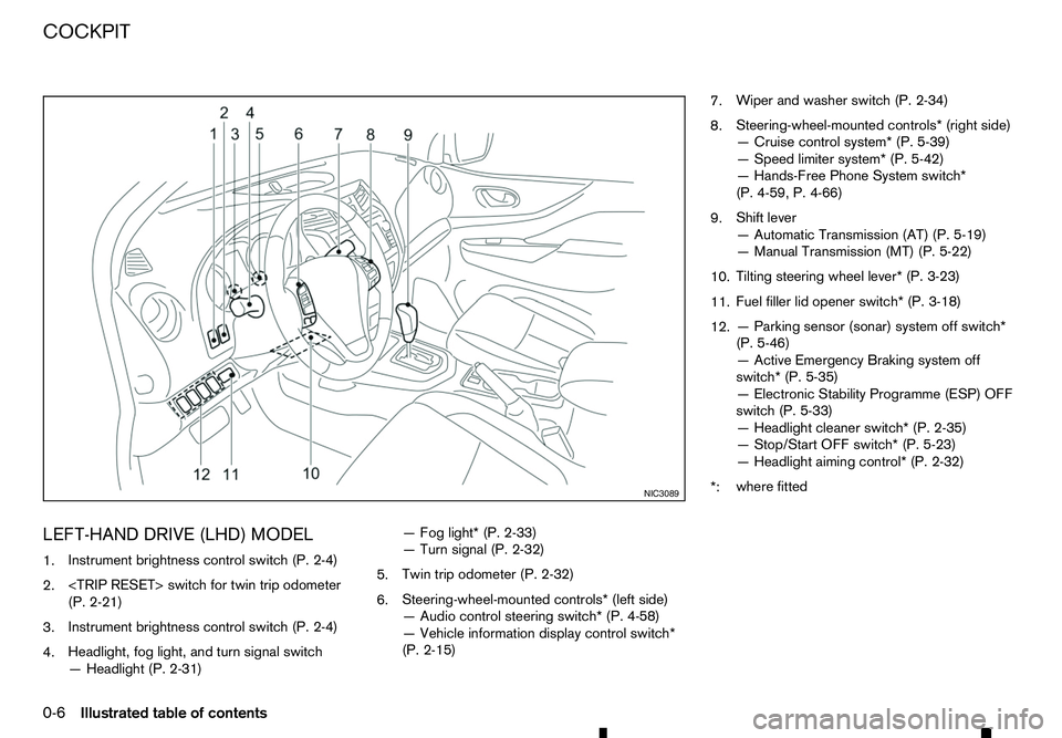
LEFT-HAND DRIVE (LHD) MODEL
1. Instrument brightness control switch (P. 2-4)
2.
(P. 2-21)
3. Instrument brightness control switch (P. 2-4)
4. Headlight, fog light, and turn signal switch
—H
eadlight (P. 2-31) —F
og light* (P. 2-33)
—T urn signal (P. 2-32)
5. Twin trip odometer (P. 2-32)
6. Steering-wheel-mounted controls* (left side)
—A
udio control steering switch* (P. 4-58)
—V ehicle information display control switch*
(P. 2-15) 7.
Wiper and washer switch (P. 2-34)
8. Steering-wheel-mounted controls* (right side)
—C
ruise control system* (P. 5-39)
—S peed limiter system* (P. 5-42)
—H ands-Free Phone System switch*
(P. 4-59, P. 4-66)
9. Shift lever
—A
utomatic Transmission (AT) (P. 5-19)
—M anual Transmission (MT) (P. 5-22)
10. Tilting steering wheel lever* (P. 3-23)
11. Fuel filler lid opener switch* (P. 3-18)
12. —P
arking sensor (sonar) system off switch*
(P. 5-46)
—A ctive Emergency Braking system off
switch* (P. 5-35)
—E lectronic Stability Programme (ESP) OFF
switch (P. 5-33)
—H eadlight cleaner switch* (P. 2-35)
—S top/Start OFF switch* (P. 5-23)
—H eadlight aiming control* (P. 2-32)
*: where fitted NIC3089
COCKPIT
0-6
Illustrated table of contents
Page 13 of 340
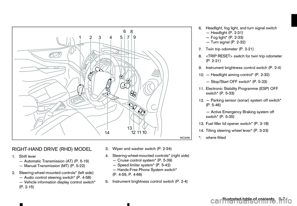
RIGHT-HAND DRIVE (RHD) MODEL
1. Shift lever
—A
utomatic Transmission (AT) (P. 5-19)
—M anual Transmission (MT) (P. 5-22)
2. Steering-wheel-mounted controls* (left side)
—A
udio control steering switch* (P. 4-58)
—V ehicle information display control switch*
(P. 2-15) 3.
Wiper and washer switch (P. 2-34)
4. Steering-wheel-mounted controls* (right side)
—C
ruise control system* (P. 5-39)
—S peed limiter system* (P. 5-42)
—H ands-Free Phone System switch*
(P. 4-59, P. 4-66)
5. Instrument brightness control switch (P. 2-4) 6.
Headlight, fog light, and turn signal switch
—H
eadlight (P. 2-31)
—F og light* (P. 2-33)
—T urn signal (P. 2-32)
7. Twin trip odometer (P. 2-21)
8.
(P. 2-21)
9. Instrument brightness control switch (P. 2-4)
10. —H
eadlight aiming control* (P. 2-32)
—S top/Start OFF switch* (P. 5-23)
11. Electronic Stability Programme (ESP) OFF
switch* (P. 5-33)
12. —P
arking sensor (sonar) system off switch*
(P. 5-46)
—A ctive Emergency Braking system off
switch* (P. 5-35)
13. Fuel filler lid opener switch* (P. 3-18)
14. Tilting steering wheel lever* (P. 3-23)
*: where fitted NIC3090
Illustrated table of contents
0-7
Page 14 of 340
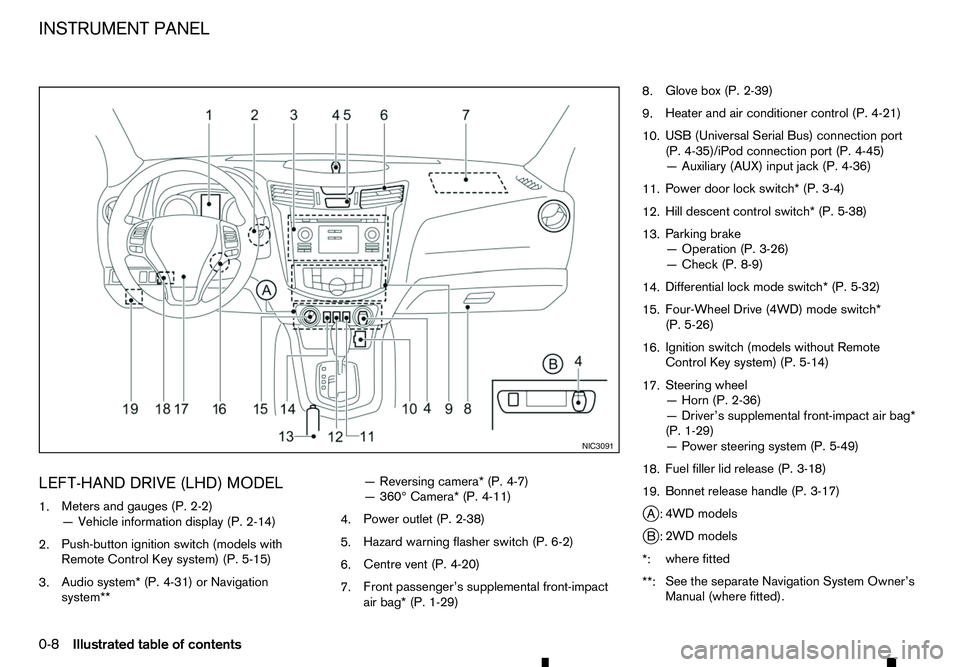
LEFT-HAND DRIVE (LHD) MODEL
1. Meters and gauges (P. 2-2)
—V ehicle information display (P. 2-14)
2. Push-button ignition switch (models with
Remote Control Key system) (P. 5-15)
3. Audio system* (P. 4-31) or Navigation
system** —R
eversing camera* (P. 4-7)
—3 60° Camera* (P. 4-11)
4. Power outlet (P. 2-38)
5. Hazard warning flasher switch (P. 6-2)
6. Centre vent (P. 4-20)
7. Front passenger’s supplemental front-impact
air bag* (P. 1-29) 8.
Glove box (P. 2-39)
9. Heater and air conditioner control (P. 4-21)
10. USB (Universal Serial Bus) connection port
(P. 4-35)/iPod connection port (P. 4-45)
—A
uxiliary (AUX) input jack (P. 4-36)
11. Power door lock switch* (P. 3-4)
12. Hill descent control switch* (P. 5-38)
13. Parking brake
—O
peration (P. 3-26)
—C heck (P. 8-9)
14. Differential lock mode switch* (P. 5-32)
15. Four-Wheel Drive (4WD) mode switch*
(P. 5-26)
16. Ignition switch (models without Remote
Control Key system) (P. 5-14)
17. Steering wheel
—H
orn (P. 2-36)
—D river’s supplemental front-impact air bag*
(P. 1-29)
—P ower steering system (P. 5-49)
18. Fuel filler lid release (P. 3-18)
19. Bonnet release handle (P. 3-17)
j A: 4WD models
j B: 2WD models
*: where fitted
**: See the separate Navigation System Owner’s
Manual (where fitted). NIC3091
INSTRUMENT PANEL
0-8 Illustrated table of contents
Page 15 of 340
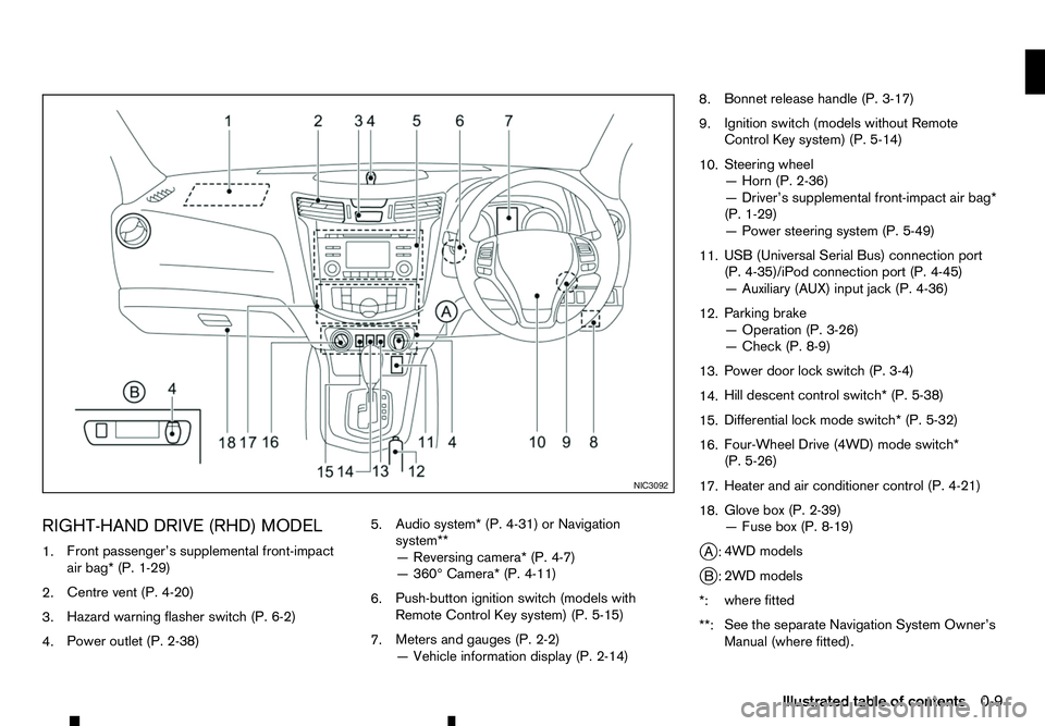
RIGHT-HAND DRIVE (RHD) MODEL
1. Front passenger’s supplemental front-impact
air bag* (P. 1-29)
2. Centre vent (P. 4-20)
3. Hazard warning flasher switch (P. 6-2)
4. Power outlet (P. 2-38) 5.
Audio system* (P. 4-31) or Navigation
system**
—R
eversing camera* (P. 4-7)
—3 60° Camera* (P. 4-11)
6. Push-button ignition switch (models with
Remote Control Key system) (P. 5-15)
7. Meters and gauges (P. 2-2)
—V
ehicle information display (P. 2-14) 8.
Bonnet release handle (P. 3-17)
9. Ignition switch (models without Remote
Control Key system) (P. 5-14)
10. Steering wheel
—H
orn (P. 2-36)
—D river’s supplemental front-impact air bag*
(P. 1-29)
—P ower steering system (P. 5-49)
11. USB (Universal Serial Bus) connection port
(P. 4-35)/iPod connection port (P. 4-45)
—A
uxiliary (AUX) input jack (P. 4-36)
12. Parking brake
—O
peration (P. 3-26)
—C heck (P. 8-9)
13. Power door lock switch (P. 3-4)
14. Hill descent control switch* (P. 5-38)
15. Differential lock mode switch* (P. 5-32)
16. Four-Wheel Drive (4WD) mode switch*
(P. 5-26)
17. Heater and air conditioner control (P. 4-21)
18. Glove box (P. 2-39)
—F
use box (P. 8-19)
j A: 4WD models
j B: 2WD models
*: where fitted
**: See the separate Navigation System Owner’s
Manual (where fitted). NIC3092
Illustrated table of contents
0-9
Page 17 of 340
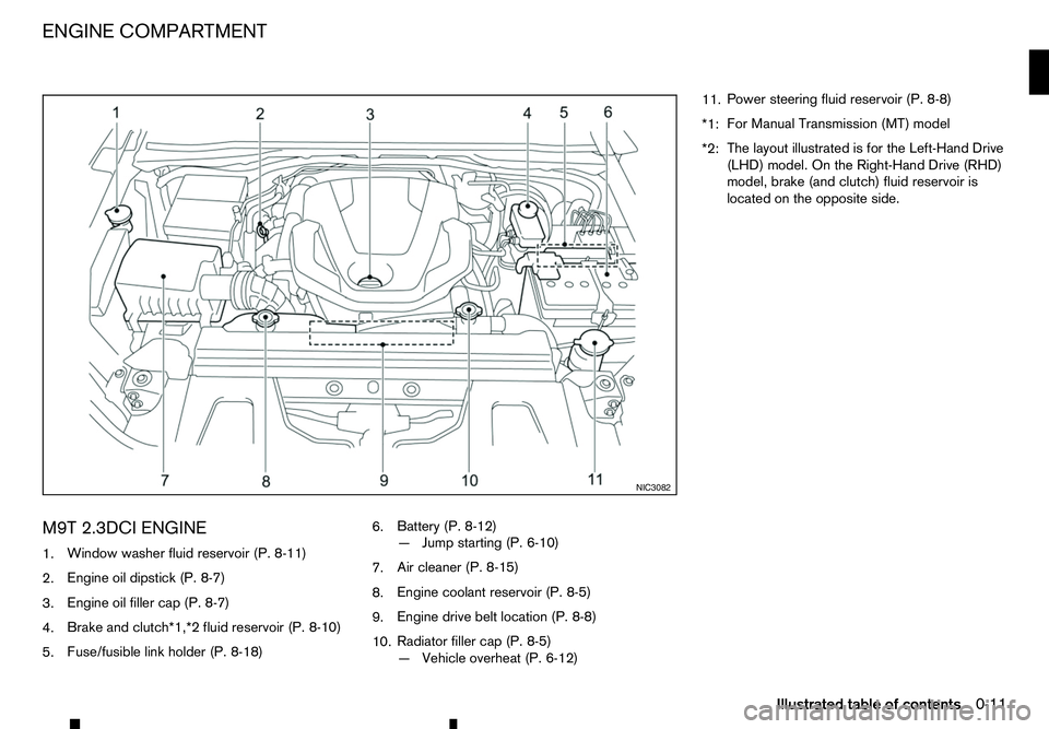
M9T 2.3DCI ENGINE
1. Window washer fluid reservoir (P. 8-11)
2. Engine oil dipstick (P. 8-7)
3. Engine oil filler cap (P. 8-7)
4. Brake and clutch*1,*2 fluid reservoir (P. 8-10)
5. Fuse/fusible link holder (P. 8-18) 6.
Battery (P. 8-12)
—J
ump starting (P. 6-10)
7. Air cleaner (P. 8-15)
8. Engine coolant reservoir (P. 8-5)
9. Engine drive belt location (P. 8-8)
10. Radiator filler cap (P. 8-5)
—V
ehicle overheat (P. 6-12) 11.
Power steering fluid reservoir (P. 8-8)
*1: For Manual Transmission (MT) model
*2: The layout illustrated is for the Left-Hand Drive
(LHD) model. On the Right-Hand Drive (RHD)
model, brake (and clutch) fluid reservoir is
located on the opposite side. NIC3082
ENGINE COMPARTMENT
Illustrated table of contents0-11
Page 48 of 340
Supplemental side-impact air bag
system (where fitted)
This system can help cushion the impact force to
the chest and pelvis area of the driver and front pas-
senger in certain side-impact collisions. The supple-
mental side-impact air bag is designed to inflate on
the side where the vehicle is impacted.
Supplemental curtain side-impact air
bag system (where fitted)
This system can help cushion the impact force to
the head of the driver and passengers in front seat-
ing positions and rear outboard seating positions
(where fitted) in certain side-impact collisions. The
supplemental curtain side-impact air bag is designed
to inflate on the side where the vehicle is impacted.
The SRS is designed to supplementthe accident
protection provided by the driver’s and passenger’s
seat belts and is notdesigned to substitutefor
them. The SRS can help save lives and reduce seri-
ous injuries. However, inflating air bags may cause
abrasions or other injuries. Air bags do not provide
protection to the lower body. Seat belts should al-
ways be correctly worn and the occupants should
always be seated asuitable distance away from the
steering wheel, instrument panel and door finishers.
(See “Seat belts” earlier in this section.) The air
bags inflate quickly in order to help protect the oc-
cupants. The force of the air bags inflating can in-
crease the risk of injury if the occupants are too
close to, or are against, the air bag modules during
inflation. The air bags will deflate quickly after de-
ployment. The SRS operates only when the ignition switch
is in the ON position.
When the ignition switch is in the ON position,
the SRS air bag warning light illuminates for
about
7seconds and then turns off. This indi-
cates that the SRS is operational. (See “Warning
lights, indicator lights and audible reminders” in
the “2. Instruments and controls” section.)
1-30 Safety —seats, seat belts and supplemental restraint system
Page 49 of 340
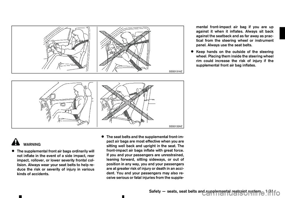
WARNING
• The supplemental front air bags ordinarily will
not inflate in the event of aside impact, rear
impact, rollover, or lower severity frontal col-
lision. Always wear your seat belts to help re-
duce the risk or severity of injury in various
kinds of accidents. •
The seat belts and the supplemental front-im-
pact air bags are most effective when you are
sitting well back and upright in the seat. The
front-impact air bags inflate with great force.
If you and your passengers are unrestrained,
leaning forward, sitting sideways, or out of
position in any way, you and your passengers
are at greater risk of injury or death in an acci-
dent. You and your passengers may also re-
ceive serious or fatal injuries from the supple- mental front-impact air bag if you are up
against it when it inflates. Always sit back against the seatback and as far away as prac-
tical from the steering wheel or instrument
panel. Always use the seat belts.
• Keep hands on the outside of the steering
wheel. Placing them inside the steering wheel
rim could increase the risk of injury if the
supplemental front air bag inflates. SSS0131AZ
SSS0132AZ
Safety —seats, seat belts and supplemental restraint system
1-31
Page 54 of 340
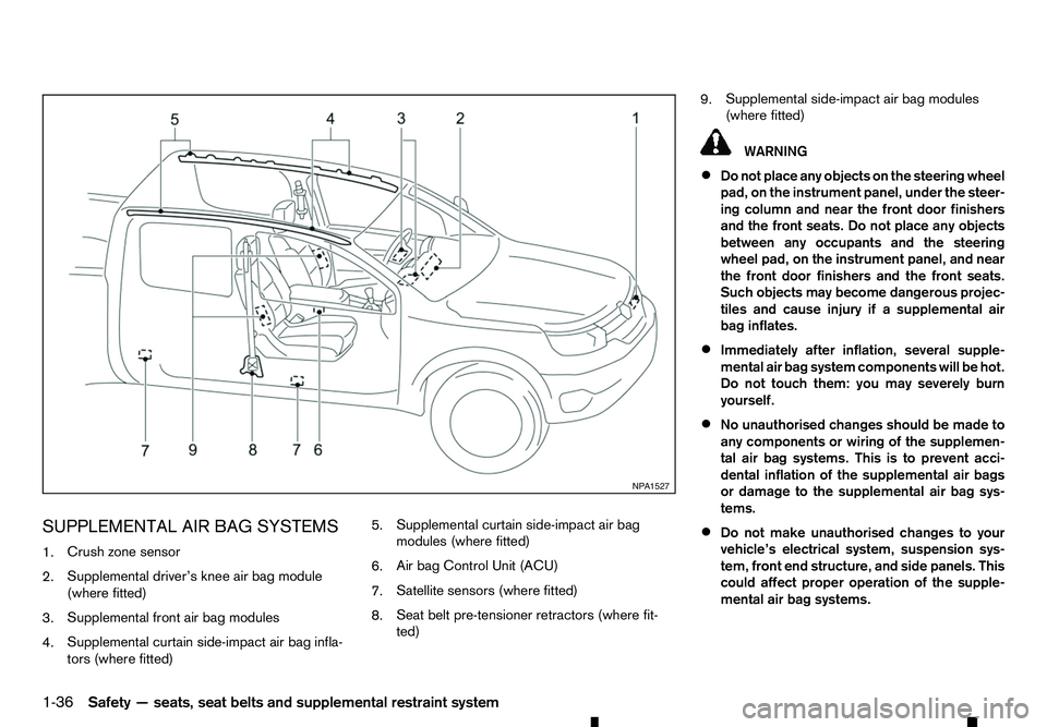
SUPPLEMENTAL AIR BAG SYSTEMS
1. Crush zone sensor
2. Supplemental driver’s knee air bag module
(where fitted)
3. Supplemental front air bag modules
4. Supplemental curtain side-impact air bag infla-
tors (where fitted) 5.
Supplemental curtain side-impact air bag
modules (where fitted)
6. Air bag Control Unit (ACU)
7. Satellite sensors (where fitted)
8. Seat belt pre-tensioner retractors (where fit-
ted) 9.
Supplemental side-impact air bag modules
(where fitted) WARNING
• Do not place any objects on the steering wheel
pad, on the instrument panel, under the steer-
ing column and near the front door finishers
and the front seats. Do not place any objects
between any occupants and the steering
wheel pad, on the instrument panel, and near
the front door finishers and the front seats.
Such objects may become dangerous projec-
tiles and cause injury if asupplemental air
bag inflates.
• Immediately after inflation, several supple-
mental air bag system components will be hot.
Do not touch them: you may severely burn
yourself.
• No unauthorised changes should be made to
any components or wiring of the supplemen-
tal air bag systems. This is to prevent acci-
dental inflation of the supplemental air bags
or damage to the supplemental air bag sys-
tems.
• Do not make unauthorised changes to your
vehicle’s electrical system, suspension sys-
tem, front end structure, and side panels. This
could affect proper operation of the supple-
mental air bag systems. NP A1527
1-36 Safety —seats, seat belts and supplemental restraint system
Page 55 of 340
•
Tampering with the supplemental air bag sys-
tems may result in serious personal injury.
Tampering includes changes to the steering
wheel and the instrument panel by placing
materials over the steering wheel pad and
above, around or on the instrument panel or
by installing additional trim materials around
the supplemental air bag systems.
• Work on and around the supplemental air bag
systems should be done by an approved
dealer or qualified workshop. The SRS wiring
should not be modified or disconnected. Un-
authorised electrical test equipment and
probing devices should not be used on the
supplemental air bag systems.
• The SRS wiring harness connectors are yel-
low for easy identification.
• Never install
arear-facing child restraint sys-
tem on the front passenger seat without first
deactivating the passenger air bag with the
front passenger air bag switch. In afrontal
collision, supplemental front-impact air bags
inflate with great force. An inflating supple-
mental front-impact air bag could seriously
injure or kill your child.
When the air bags inflate, afairly loud noise may be
heard, followed by the release of smoke. This smoke
is not harmful and does not indicate afire. Care
should be taken not to inhale it, as it may cause irri-
tation and choking. Those with ahistory of abreath-
ing condition should get fresh air promptly. Supplemental front-impact air bag
system
The driver’s supplemental front-impact air bag is
located at the centre of the steering wheel. The pas-
senger’s supplemental front-impact air bag is lo-
cated at the instrument panel above the glove box.
The supplemental front-impact air bag system is de-
signed to inflate in higher severity frontal collisions,
although it may inflate if the forces in another type of
collision are similar to those of
ahigher severity fron-
tal impact. It may not inflate in certain frontal colli-
sions. Vehicle damage (or lack of it) is not always an
indication of proper supplemental front-impact air
bag system operation. WARNING
Never install
arear-facing child restraint system
on the front passenger seat without first deacti-
vating the passenger air bag with the front pas-
senger air bag switch (where fitted), see “Front
passenger air bag switch (where fitted)” later in
this section. In afrontal collision, supplemental
front-impact air bags inflate with great force. An
inflating supplemental front-impact air bag could
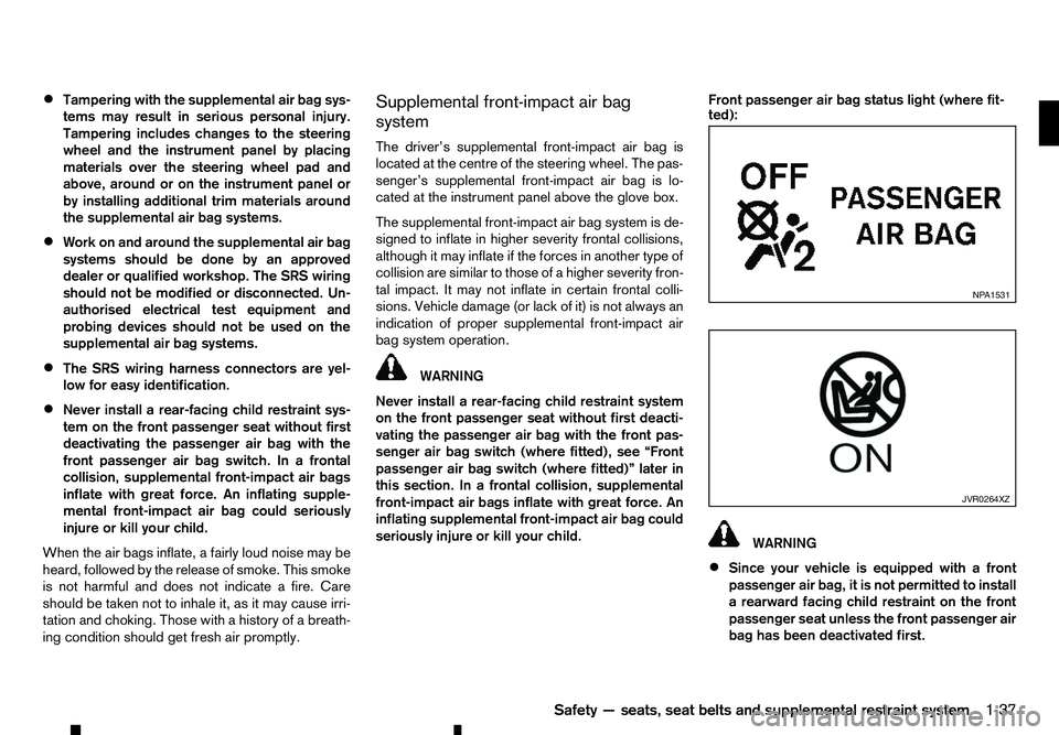
seriously injure or kill your child. Front passenger air bag status light (where fit-
ted):
WARNING
• Since your vehicle is equipped with
af
ront
passenger air bag, it is not permitted to install
ar earward facing child restraint on the front
passenger seat unless the front passenger air
bag has been deactivated first. NP A1531
JVR0264XZ
Safety —seats, seat belts and supplemental restraint system
1-37
Page 56 of 340
•
Do not fit
arearward facing child seat on the
front passenger seat if the air bag activation/
deactivation system (where fitted) is malfunc-
tioning. Your vehicle must immediately be
taken to an approved dealer or qualified work-
shop in such asituation.
The front passenger air bag status lights and
are located on the instrument panel between
the centre vents.
When the ignition switch is placed in the ON posi-
tion, the front passenger air bag status ON and
OFF lights illuminate and then turn off or remain on
depending on the front passenger air bag status.
• When the ignition switch is placed in the ON
position and the front passenger air bag is ac-
tive, both the front passenger air bag status OFF
light ,a
nd the Supplemental Restraint Sys-
tem (SRS) air bag warning light in the com-
bination meter ➀will turn off after about
7sec-
onds.
The front passenger air bag status ON light will illuminate and then turn off after
aperiod of
time when the front passenger air bag switch is
in the ON position.
• When the ignition switch is placed in the ON
position and the front passenger air bag is inac-
tive, both the front passenger air bag status ON
light ,a
nd the Supplemental Restraint Sys-
tem (SRS) air bag warning light in the com-
bination meter ➀will turn off after about
7sec-
onds. The front passenger air bag status OFF light will illuminate and remain on as long as the
front passenger air bag switch is in the OFF
position.
If the front passenger air bag status light operates in
aw ay other than described above, the front passen-
ger air bag may not function properly. Have the sys-
tem checked, and if necessary repaired, by an ap-
proved dealer or qualified workshop promptly.
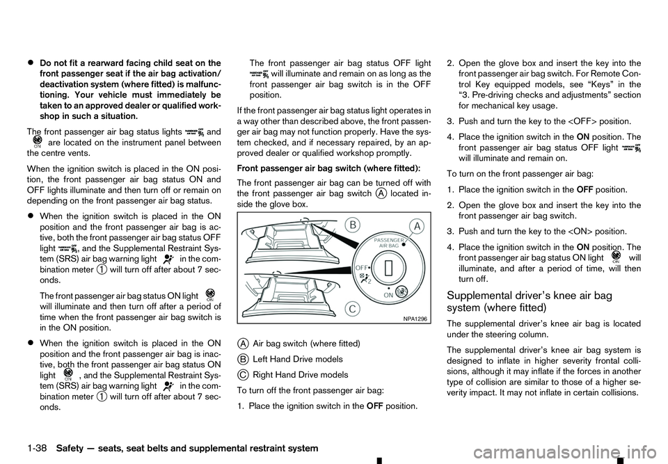
Front passenger air bag switch (where fitted):
The front passenger air bag can be turned off with
the front passenger air bag switch j
Al ocated in-
side the glove box.
j A Air bag switch (where fitted)
j B Left Hand Drive models
j C Right Hand Drive models
To turn off the front passenger air bag:
1. Place the ignition switch in the OFFposition. 2. Open the glove box and insert the key into the
front passenger air bag switch. For Remote Con-
trol Key equipped models, see “Keys” in the
“3. Pre-driving checks and adjustments” section
for mechanical key usage.
3. Push and turn the key to the
4. Place the ignition switch in the ONposition. The
front passenger air bag status OFF light will illuminate and remain on.
To turn on the front passenger air bag:
1. Place the ignition switch in the OFFposition.
2. Open the glove box and insert the key into the front passenger air bag switch.
3. Push and turn the key to the
4. Place the ignition switch in the ONposition. The
front passenger air bag status ON light will
illuminate, and after
aperiod of time, will then
turn off.
Supplemental driver’s knee air bag
system (where fitted)
The supplemental driver’s knee air bag is located
under the steering column.
The supplemental driver’s knee air bag system is
designed to inflate in higher severity frontal colli-
sions, although it may inflate if the forces in another
type of collision are similar to those of ahigher se-
verity impact. It may not inflate in certain collisions. NP A1296
1-38 Safety —seats, seat belts and supplemental restraint system