wheel bolts RENAULT KANGOO 1997 KC / 1.G Chassis User Guide
[x] Cancel search | Manufacturer: RENAULT, Model Year: 1997, Model line: KANGOO, Model: RENAULT KANGOO 1997 KC / 1.GPages: 105
Page 31 of 105
Emb. 880 Inertia extraction tool
Rou. 943 Hub cover plug extractor
REAR AXLE
Brake linings (drum)
SPECIAL TOOLING REQUIRED
Wheel bolts 9
Hub nut 17.5
33
TIGHTENING TORQUES (in daN.m)
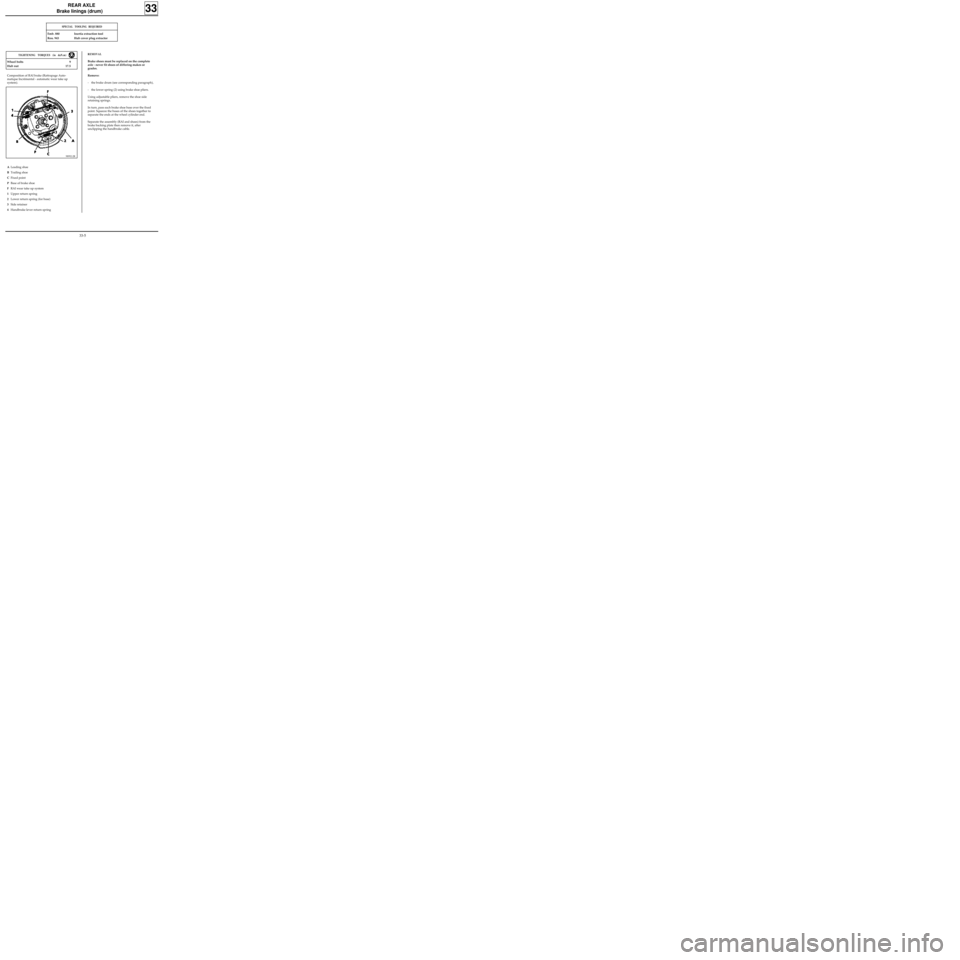
Composition of RAI brake (Rattrapage Auto-
matique Incrémental - automatic wear take up
system).
ALeading shoe
BTrailing shoe
CFixed point
PBase of brake shoe
FRAI wear take up system
1Upper return spring
2Lower return spring (for base)
3Side retainer
4Handbrake lever return spring
REMOVAL
Brake shoes must be replaced on the complete
axle - never fit shoes of differing makes or
grades.
Remove:
- the brake drum (see corresponding paragraph),
- the lower spring (2) using brake shoe pliers.
Using adjustable pliers, remove the shoe side
retaining springs.
In turn, pass each brake shoe base over the fixed
point. Squeeze the bases of the shoes together to
separate the ends at the wheel cylinder end.
Separate the assembly (RAI and shoes) from the
brake backing plate then remove it, after
unclipping the handbrake cable.
98992-2R
33-5
Page 33 of 105
REAR AXLE
Bearing
SPECIAL TOOLING REQUIRED
Emb. 880 Inertia extraction tool
Rou. 943 Hub plug extractor
TIGHTENING TORQUES (in daN.m)
CHECKING
Check the end float using a dial gauge mounted
on the drum : 0 to 0.03 mm maximum.
REMOVAL
Remove:
- the hub plug using tools Rou. 943 + Emb. 880,
- the brake drum (see corresponding
paragraph).
From the drum, remove:
- the bearing retaining clip,
- the bearing using a tube.
Hub nut 17.5
Wheel bolts 9
33
REFITTING
Using a tube and a press, fit the bearing until it
touches the shoulder.
Fit:
-a new clip,
- the drum on the pre-lubricated stub axle,
-a new lock nut and tighten to the correct
torque,
- the hub plug.
Adjust:
- the brake shoes by repeatedly pressing the
brake pedal,
- the handbrake (see section 37 "Controls").
33-7
Page 34 of 105
REAR AXLE
Shock absorber
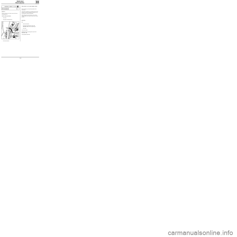
REMOVAL
With the vehicle on its wheels, remove the lower
mounting bolt (1).
Lift the vehicle and remove:
- the wheel,
- the upper mounting bolt (2),
- the shock absorber.
PRECAUTIONS TO BE TAKEN BEFORE FITTING
Shock absorbers are stored horizontally in the
Parts Stores.
Under these conditions it is possible that the shock
absorbers, which are designed to operate in a ver-
tical direction, will have de-primed.
Before fitting the shock absorbers to the vehicle
compress them a few times by hand in the vertical
position.
REFITTING
Fit:
- the shock absorber,
- the upper mounting bolt coated with
MOLYKOTE BR2, without tightening it,
- the wheel.
Lower the vehicle.
Position the lower mounting bolt coated with
MOLYKOTE BR2.
Torque tighten both bolts.
33
Upper mounting bolt 11.5
Lower mounting bolt 8.5
TIGHTENING TORQUES (in daN.m)
13133R
33-8
Page 35 of 105

REAR AXLE
Anti-roll bar, tubular rear axle
TIGHTENING TORQUES (in daN.m)
Bar mounting bolt 5.5
REMOVAL
1Mounting bolt
Put the vehicle on a lift with the wheels hanging
free.
On each side, remove bolts (1) and retain the
captive nuts.
Remove the bar.
REFITTING
On each side, refit the bolts (1) with the captive
nuts.
Tighten to the recommended torque.
33
13132R
33-9
Page 36 of 105
REAR AXLE
Half suspension arms, tubular rear axle
REFITTING
Ensure the bearing races or the needle bearings
are in perfect condition, otherwise replace them
(see section "Bushes, tubular rear axle").
The needle bearings are greased for life and do
not require further lubrication.
NOTE : new suspension arms are supplied by the
Parts Department fitted with bearing races or
needle bearings (depending on side).
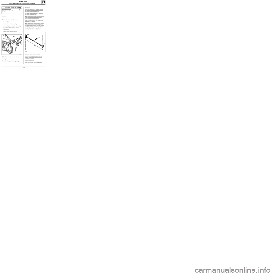
Fit the two half suspension arms together until
dimension (B) is obtained.
NOTE : dimension (B) corresponds to the distance
between the same two mounting points for the
anti-roll bar on the suspension arms. It is therefore
possible to obtain this dimension by positioning
the anti-roll bar in its location and checking the
mounting bolts can be correctly positioned.
Ensure the fitting direction is observed.
Refitting is then the reverse of removal.
NOTE : if the half suspension arm is renewed,
bond the brake backing plate mounting bolts
with
Loctite FRENBLOC.
Bleed the brake circuit.
Adjust the handbrake control (see section 37).
33
TIGHTENING TORQUES (in daN.m)
Bearing mounting nut 11
Anti-roll bar mounting bolt 5.5
Wheel bolt 9
Shock absorber base bolt 8.5
REMOVAL
Put the vehicle on a two post lift, remove:
- the anti-roll bar,
- the lower shock absorber mounting,
- the secondary handbrake cable, disconnecting
at the central adjuster under the vehicle,
- the brake pipe,
- the two bearing mounting nuts (A).
Slacken the two nuts (A) on the other bearing so
the half suspension arm can be released from its
mountings.
Remove the half suspension arm, separating one
from the other.
13132R1
86320R
33-10
Page 43 of 105
REAR AXLE
Four bar rear axle
SPECIAL TOOLING REQUIRED
Emb. 880 Inertia extractor
TIGHTENING TORQUES (in daN.m)
Upper shock absorber mounting 8.5
Lower shock absorber mounting 11.5
Wheel bolts 9
REMOVAL
Remove:
- the wheels,
- the shock absorbers,
- the suspension bar plugs.
Remove using tool Emb. 880 :
- the two suspension bars,
- the two anti-roll bars, retaining the central
shackle.
Clean and lubricate the bar splines using
MOLYKOTE BR2.
REFITTING
The anti-roll bars cannot be removed from the
vehicle when the shock absorber replacement tool
is in position. Because of this, and to make it
easier to refit the shackle, a wooden block must
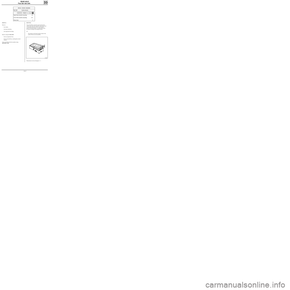
be made according to the diagram below.
Fit:
- the shackle on the block (locally made) in the
centre of the rear axle assembly,
33
13135R
Dimensions in mm and degrees ( ° ).
33-17
Page 49 of 105
Offset
(in mm)
DI3501
WHEELS AND TYRES
Specifications
WHEEL RIMS
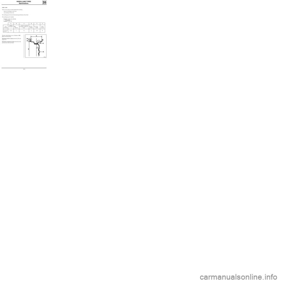
There are two forms of wheel identification marking:
- engraved markings for steel rims,
- cast marking for alloy rims.
The marking gives the main dimensional specifications of the wheel.
The marking may be complete:
Example : 5 1/2 J 14 4 CH 36
or simplified
Example : 5 1/2 J 14
35
The four wheel bolts are over a diameter of 100
mm (4 mounting bolts).
Maximum run-out: 1.2 mm measured on the rim
edge (at G).
Maximum eccentricity: 0.8 mm measured on the
pressure face of the tyre beads.
FE
Number
of holes
DCB
WIDTH
(in inches)
5 1/2
A
TYPE
OF WHEEL
5 1/2 J 14
4 CH 36J144CH36
RIM
PROFILE
NOMINAL DIAMETER
(in inches). under tyre
beadTyre bead
profile
35-1
Page 53 of 105
STEERING ASSEMBLY
Axial ball joint
36
Put the vehicle on a two post lift.
REMOVAL
Disconnect the track rod end using tool T.Av. 476.
Slacken the bolt on the parallelism adjustment
sleeve and slacken the track rod end while
holding the axial ball joint using an open wrench.
Make a mark or count the number of turns of
thread taken up so the parallelism can be pre-
adjusted on refitting.
Remove the plastic retaining clip for the gaiter
and remove the gaiter.
SPECIAL TOOLING REQUIRED
Wheel bolts 9
Track rod end nut 3.7
Bolt on parallelism adjustment sleeve 1.7
Axial ball joint 5
Dir. 1305-01 Tool for removing - refitting
axial ball joint
Dir. 1306 Tool for retaining SMI unit rack
T.Av. 476 Ball joint extractor
TIGHTENING TORQUES (in daN.m)Turn the wheels so the rack teeth are freed on the
valve side.
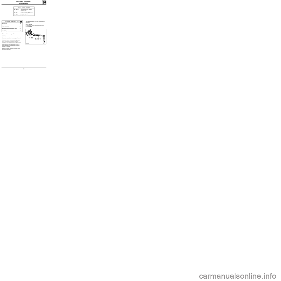
Fit tool Dir. 1306.
In this position, release the axial ball joint using
tool Dir. 1305-01.
97469R1
36-1
Page 55 of 105
STEERING ASSEMBLY
Manual steering rack
36
Put the vehicle on a two post lift.
REMOVAL
Remove the front wheels.
Cut the rubber gaiter retaining clip and push the
gaiter back towards the bulkhead.
Disconnect the ball joints using tool T.Av. 476.
Remove:
- the universal joint eccentric bolt,
- the steering rack mounting bolts on the sub-
frame.
Remove the steering rack.
SPECIAL TOOLING REQUIRED
Wheel bolts 9
Track rod end nut 3.7
Steering rack mounting bolts 5.5
Universal joint eccentric bolt 2.5
T.Av. 476 Ball joint extractor
TIGHTENING TORQUES (in daN.m)REFITTING
Refitting is the reverse of removal. Observe the
recommended tightening torques.
If a new steering rack is being fitted, fit the track
rod ends in the position noted on removal.
To do this, slacken the bolt on the parallelism
adjustment sleeve and slacken the track rod end
while holding the axial ball joint using an open
wrench.
Make a mark or count the number of turns of
thread taken up so the parallelism can be pre-
adjusted on refitting.
Check the parallelism.
NOTE : the markings on the track rod ends MUST
BE OBSERVED
(one mark on right hand joint, two
marks on left hand joint).
36-3
Page 56 of 105
STEERING ASSEMBLY
Power assisted steering rack
36
SPECIAL TOOLING REQUIRED
Mot. 453-01 Hose clamp pliers
T.Av. 476 Ball joint extractor
Wheel bolts 9
Track rod end nut 3.7
Steering rack mounting bolt 5
Universal joint eccentric bolt 2.5
Engine tie bar bolt 6.5
TIGHTENING TORQUES (in daN.m)
Put the vehicle on a two post lift.
REMOVAL
Remove the front wheels.
Fit a clamp Mot. 453-01 to each of the pipes from
the oil reservoir.
NOTE :never clamp the high pressure pipes.
Cut the rubber gaiter retaining clip and push the
gaiter back towards the bulkhead.
Disconnect the ball joints using tool T.Av. 476.
Remove the universal joint eccentric bolt.
Disconnect the oxygen sensor.
Remove the exhaust downpipe.
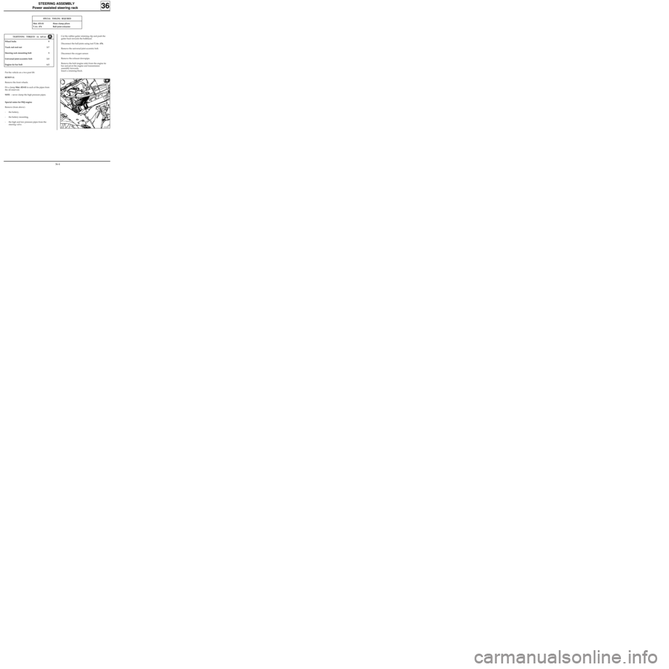
Remove the bolt (engine side) from the engine tie
bar and pivot the engine and transmission
assembly forwards.
Insert a retaining block.
Special notes for F8Q engine
Remove (from above) :
- the battery,
- the battery mounting,
- the high and low pressure pipes from the
steering valve.
13120S
36-4