RENAULT KANGOO 1997 KC / 1.G Engine And Peripherals User Guide
KANGOO 1997 KC / 1.G
RENAULT
RENAULT
https://www.carmanualsonline.info/img/7/1731/w960_1731-0.png
RENAULT KANGOO 1997 KC / 1.G Engine And Peripherals User Guide
Page 131 of 208
ANTIPOLLUTION
Fuel vapour rebreathing
14
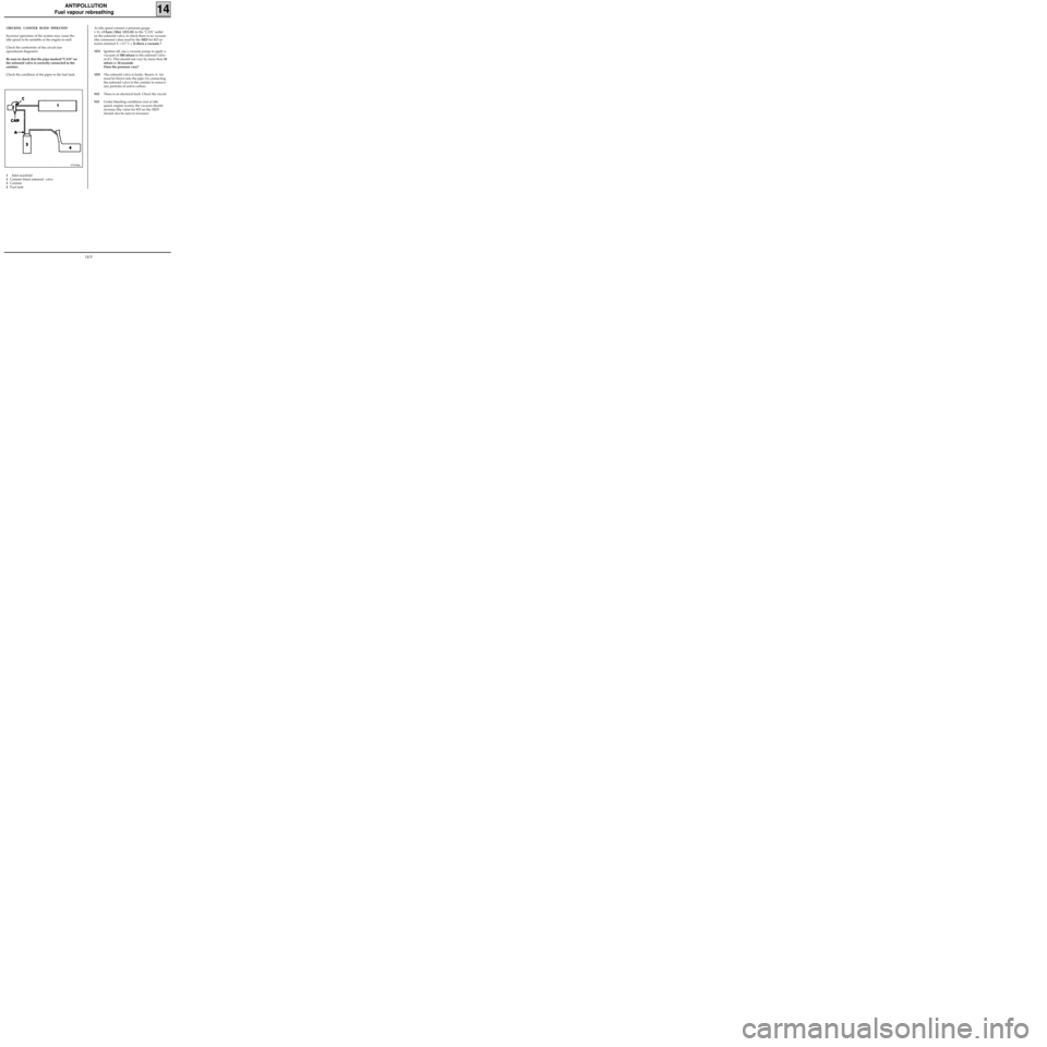
CHECKING CANISTER BLEED OPERATION
Incorrect operation of the system may cause the
idle speed to be unstable or the engine to stall.
Check the conformity of the circuit (see
operational diagrams)
Be sure to check that the pipe marked "CAN" on
the solenoid valve is correctly connected to the
canister.
Check the condition of the pipes to the fuel tank.
97393R6
1Inlet manifold
2Canister bleed solenoid valve
3Canister
4Fuel tankAt idle speed connect a pressure gauge
(- 3 ; +3 bars) (Mot. 1311-01) to the "CAN" outlet
on the solenoid valve, to check there is no vacuum
(the command value read by the
XR25 for #23 re-
mains minimal X = 0.7 % ). Is there a vacuum ?
YESIgnition off, use a vacuum pump to apply a
vacuum of 500 mbars to the solenoid valve
at (C). This should not vary by more than 10
mbars in 30 seconds.
Does the pressure vary?
YESThe solenoid valve is faulty. Renew it. Air
must be blown into the pipe (A) connecting
the solenoid valve to the canister to remove
any particles of active carbon.
NOThere is an electrical fault. Check the circuit.
NOUnder bleeding conditions (not at idle
speed, engine warm), the vacuum should
increase (the value for #23 on the XR25
should also be seen to increase).
14-5
Page 133 of 208
ANTIPOLLUTION
Oil vapour rebreathing
14
CIRCUIT DIAGRAM
1 Cylinder head cover
2 Inlet manifold
3 Oil vapour rebreathing pipe connected upstream from the throttle body (the circuit is used
for medium and high loads)
4 Oil vapour rebreathing pipe connected downstream from the throttle body
5 Air pipe
6 Throttle body
99932R
D7F Engine
14-7
Page 135 of 208
ANTIPOLLUTION
Oil vapour rebreathing
14E7J Engine
CIRCUIT DIAGRAM
1 Cylinder head
2 Inlet manifold
3 Oil vapour rebreathing pipe connected
upstream from the throttle body (the circuit is
used for medium and high loads)
4 Oil vapour rebreathing pipe connected
downstream from the throttle body
CHECKING
To ensure the correct operation of the
antipollution system, it is important to keep the
oil vapour rebreathing system clean and in good
working condition.
13335R
14-9
Page 178 of 208
COOLING
Diagram
19
1 Engine
2 Radiator
3 ”Hot” bottle with permanent degassing
4 Heater matrix
5 3 mm diameter restriction
The fan assembly is controlled at high speed by
the injection computer if the coolant tempera-
ture is greater than 99°C.
If the coolant temperature is lower than 96°C, the
fan assembly stops operating.Water pump
Thermostat
Bleed screw
The expansion bottle valve is brown, and its rating
is 1.2 bar.
10070-2R
D7F Engine
19-4
Page 179 of 208
COOLING
Diagram
19
1 Heater
2 Radiator
3 ”Hot” bottle with permanent degassing
4 Heater matrix
5 Thermostat mounting
6 3 mm diameter restriction
The fan assembly is controlled at high speed by
the injection computer if the coolant tempera-
ture is greater than 99°C.
If the coolant temperature is lower than 96°C, the
fan assembly stops operating.Water pump
Thermostat
Bleed screw
Temperature switch
The expansion bottle valve rating is 1.2 bar
(colour:brown).
13508R
E7J Engine
19-5
Page 180 of 208
COOLING
Diagram
19
Water pump
Thermostat
Bleed screw
Temperature switch
13504R
F8Q Engine
1 Heater
2 Radiator
3 ”Hot” bottle with permanent degassing
4 Heater matrix
5 Thermostat mounting
6 3 mm diameter restriction
The expansion bottle valve rating is 1.2 bar
(colour:brown).
19-6
Page 183 of 208
COOLING
Water pump
Refit the timing belt (see method described in
chapter 11 "Timing belt").
Fill and bleed the cooling circuit (see section 19
"Filling - Bleeding").
19
SPECIAL TOOLING REQUIRED
Mot. 591-02 Index
Mot. 591-04 Angle tightening wrench
Mot. 1135-01 Tool for tensioning the timing belt
Mot. 1202 Hose clip pliers
Mot. 1273 Tool for checking belt tension
92068R
E7J Engine
Tension wheel nut 5
Crankshaft pulley bolt 2 + 68° + 6°
Bolt for suspended engine mounting cover 6,2
Nut for suspended engine mounting cover 4,4
Water pump bolt 2,2
Water pump nut 1
Wheel bolts 9
TIGHTENING TORQUES (in daN.m)
EQUIPMENT REQUIRED
Engine support tool
REFITTING
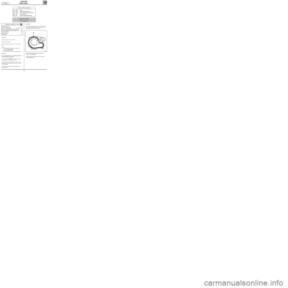
The sealing of the water pump is carried out using
the product
LOCTITE 518; the bead (H) must be
applied following the diagram below.
REMOVAL
Place the vehicle on a two post lift.
Disconnect the battery.
Drain the cooling circuit from the lower radiator
hose.
Remove:
- the timing belt (see method described in
section 11 "Timing belt),
- the timing tension wheel,
- the water pump, and extract this from above.
CLEANING
It is very important not to scratch the gasket faces
of all aluminium components.
Use the product Décapjoint to dissolve the part
of the gasket which remains attached.
Apply the product to the part to be cleaned, wait
approximately 10 minutes, then remove it using a
wooden spatula.
The wearing of gloves is recommended during
this operation.
19-9
Page 189 of 208
EXHAUST
Pipe assembly
19
DIAGRAM OF EXHAUST PIPES AND LOCATION OF CUTTING AREAS
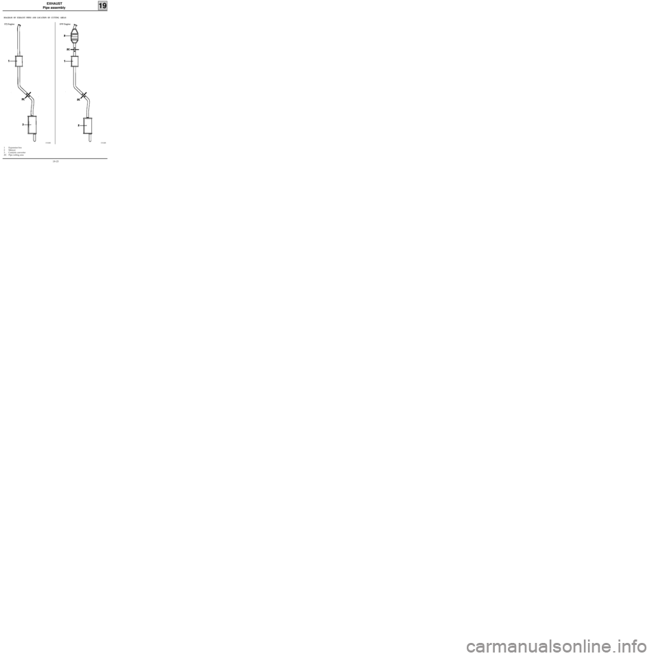
1 Expansion box
2 Silencer
3 Catalytic converter
ZC Pipe cutting area
13124R
E7J Engine D7F Engine
13126R
19-15
Page 190 of 208
EXHAUST
Pipe assembly
19
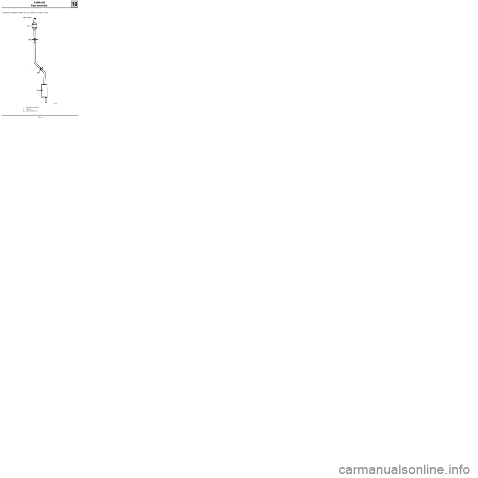
DIAGRAM OF EXHAUST PIPES AND LOCATION OF CUTTING AREAS
13125R
1 Catalytic converter
2 Silencer
ZC Pipe cutting area F8Q Engine
19-16


