torque RENAULT KANGOO 1997 KC / 1.G Engine And Peripherals Owner's Guide
[x] Cancel search | Manufacturer: RENAULT, Model Year: 1997, Model line: KANGOO, Model: RENAULT KANGOO 1997 KC / 1.GPages: 208
Page 74 of 208

FUEL MIXTURE
Inlet manifold
12D7F engine
TIGHTENING TORQUES (in daN.m)
There are no special notes for removal - refitting
TIGHTENING TORQUES (in daN.m)
Injector gallery mounting bolt on manifold 1
Manifold mounting nut on cylinder head 1.7
Manifold mounting stud on cylinder head 1
12-9
Page 75 of 208
FUEL MIXTURE
Inlet manifold
12
Inlet manifold bolt and nut 2
TIGHTENING TORQUES (in daN.m)
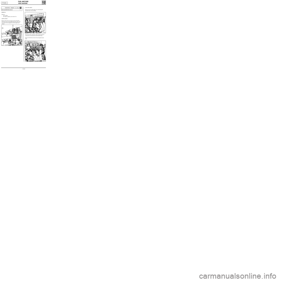
REMOVAL
Remove:
- the air filter,
- the injector gallery (see section 13).
Lift the vehicle.
Remove the strut (1) (to gain access to the bolt
fixing the strut on the right-hand side of the vehi-
cle, remove the mudguard and the right-hand
wheel).
E7J engine
13339R2
Disconnect the accelerator cable and the electrical
connectors (2) connected to the throttle body.
Remove the bolts and nuts (3) securing the mani-
fold. Lower the vehicle.
Remove the air intake pipe (A) connecting the
throttle body to the air filter.
13335-1R
13130R
12-10
Page 77 of 208
FUEL MIXTURE
Exhaust manifold
12D7F engine
Manifold mounting nut 2.5
Manifold mounting stud 1
Exhaust downpipe mounting bolt 2.2
TIGHTENING TORQUES (in daN.m)
There are no special notes for the removal - refitting.
12-12
Page 78 of 208

FUEL MIXTURE
Exhaust manifold
12
Manifold mounting bolt 2
TIGHTENING TORQUES (in daN.m)
REMOVAL
Remove the multifunction support (1) (see section
10).
Disconnect the exhaust manifold / exhaust link
(2).
Remove the heat shield (3).
Remove the exhaust manifold. E7J engine
13239R2
REFITTING
Replace the manifold gasket.
Refitting is then the reverse of removal.
12-13
Page 79 of 208
FUEL MIXTURE
Inlet/Exhaust manifolds
12F8Q engine
Manifold mounting studs on cylinder head 1
Manifold mounting nuts on cylinder head 2.7
Inlet manifold strut mounting bolt 2.5
Cylinder block strut mounting bolt 2.5
TIGHTENING TORQUES (in daN.m)
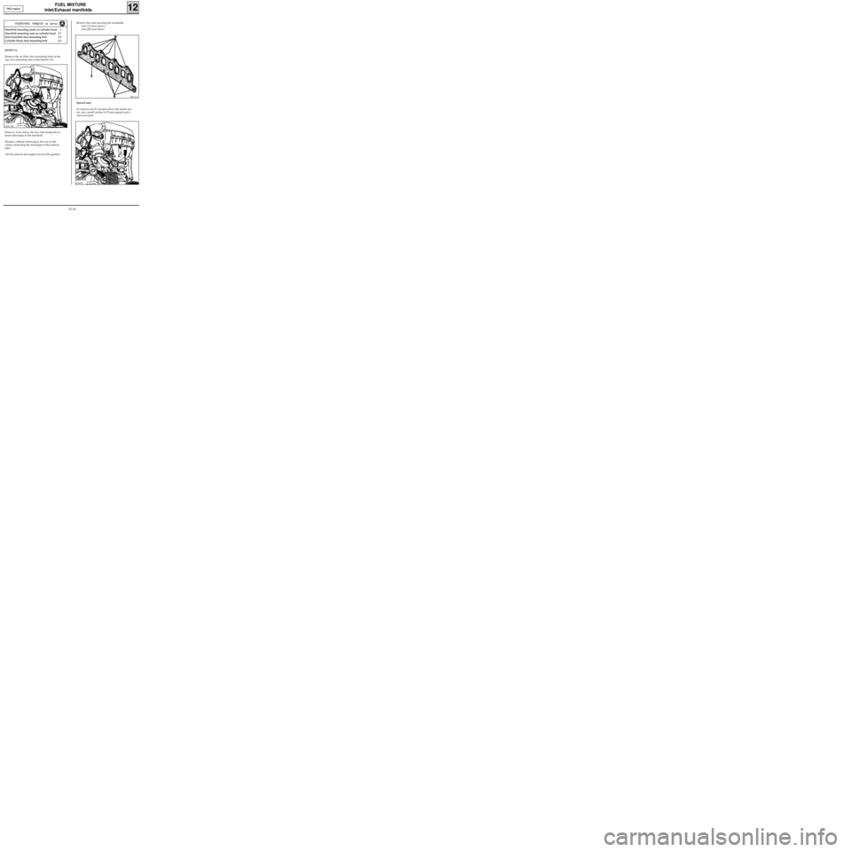
REMOVAL
Remove the air filter (two mounting bolts at the
top, two mounting nuts at the bottom (1)).
Remove, from above, the two nuts fixing the ex-
haust downpipe to the manifold.
Slacken, without removing it, the nut on the
clamp connecting the downpipe to the exhaust
pipe.
Tilt the exhaust downpipe towards the gearbox.
Remove the nuts securing the manifolds:
- nuts (A) from above,
- nuts (B) from below.
PRO12.1
Special note
To remove nut (C) located above the starter mo-
tor, use a small ratchet (6.35 mm square) and a
universal joint.
13047-1R1
13047R
12-14
Page 82 of 208
FUEL SUPPLY
Injector gallery
13
IMPORTANT: during the opening of the fuel cir-
cuit , be sure to use a cloth to avoid possible pro-
jections of fuel due to the residual pressure.
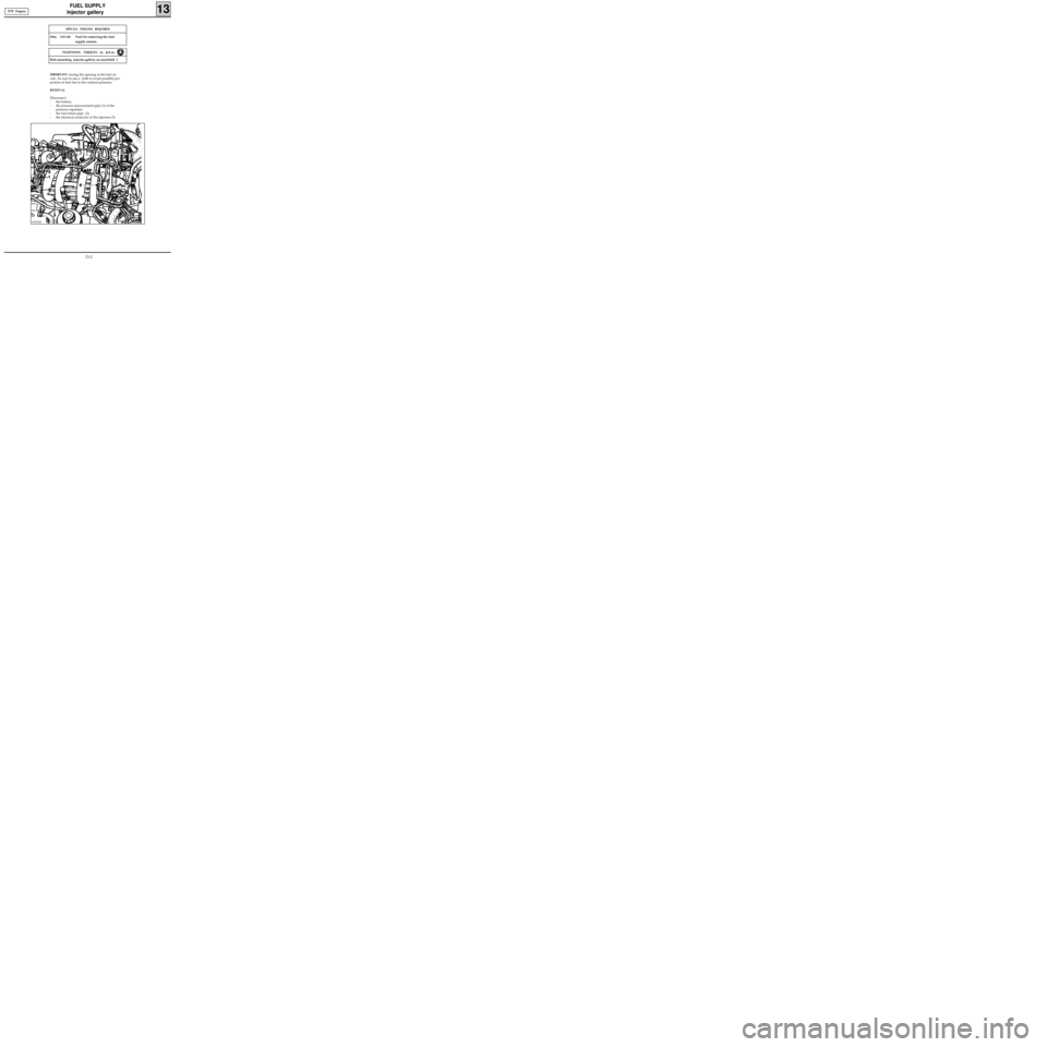
REMOVAL
Disconnect :
- the battery,
- the pressure measurement pipe (1) of the
pressure regulator,
- the fuel return pipe (2),
- the electrical connector of the injectors (3)
99937R3
SPECIAL TOOLING REQUIRED
Mot. 1311-06 Tool for removing the fuel
supply unions
Bolt mounting injector gallery on manifold 1
TIGHTENING TORQUES (in daN.m)
D7F Engine
13-2
Page 95 of 208
DIESEL EQUIPMENT
Specifications
13
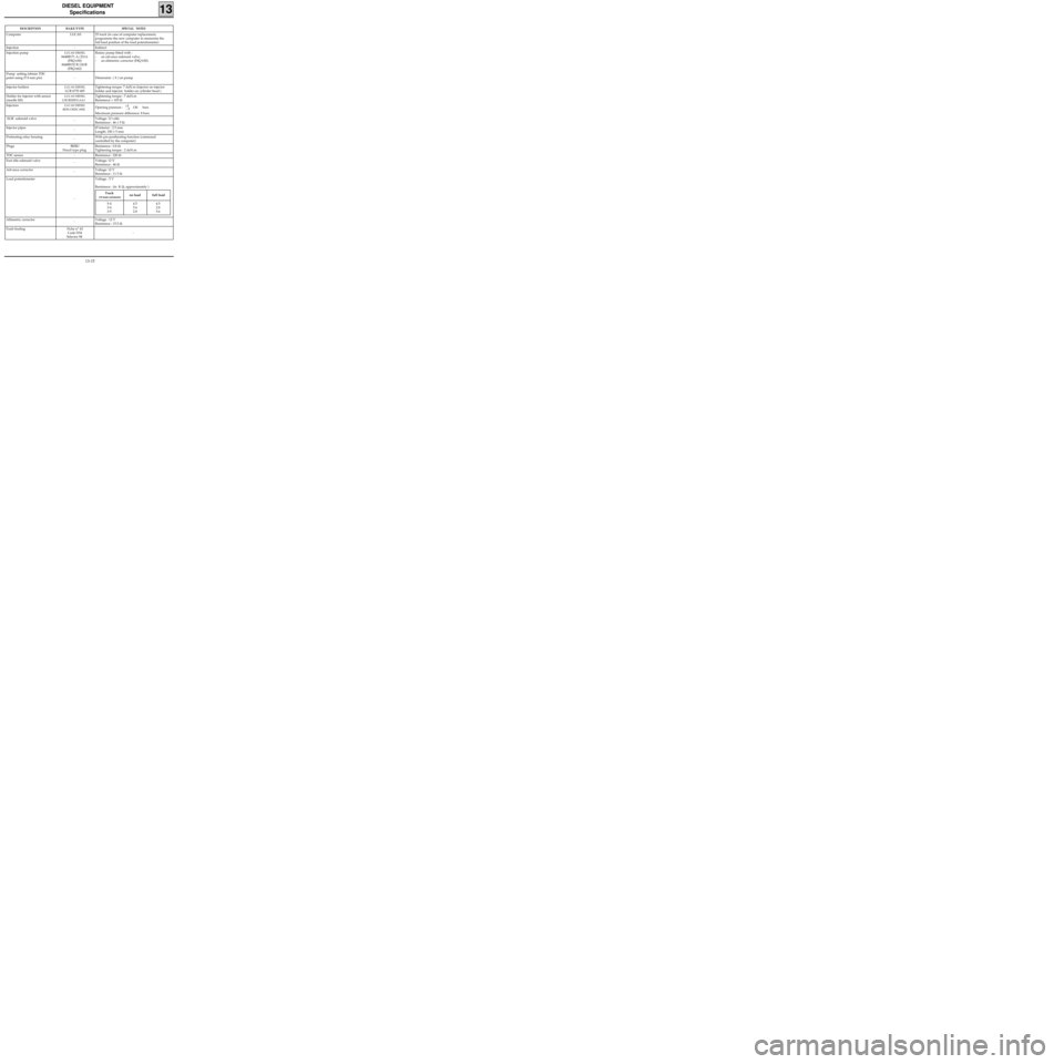
DESCRIPTIONMAKE/TYPESPECIAL NOTES
Computer LUCAS 25 track (in case of computer replacement,
programme the new computer to memorise the
full load position of the load potentiometer)
Injection - Indirect
Injection pump
LUCAS DIESEL
8448B171 A/231A
(F8Q 630)
8448B152 B/241B
(F8Q 662)Rotary pump fitted with :
- an advance solenoid valve,
- an altimetric corrector (F8Q 630).
Pump setting (obtain TDC
point using ∅ 8 mm pin) - Dimension ( X ) on pump
Injector holders
LUCAS DIESEL
LCR 6735 405Tightening torque: 7 daN.m (injector on injector
holder and injector holder on cylinder head )
Holder for injector with sensor
(needle lift)
LUCAS DIESEL
LDCR020011AA1Tightening torque : 7 daN.m
Resistance ≈ 105 Ω
Injectors
LUCAS DIESEL
RDN OSDC 6902Opening pressure : 130 bars
Maximum pressure difference: 8 bars
EGR solenoid valve
-Voltage: 12 volts
Resistance : 46 ± 5 Ω
Injector pipes
-Ø interior : 2.5 mm
Length: 330 ± 5 mm
Preheating relay housing
-With pre-postheating function (command
controlled by the computer)
Plugs BERU
Pencil type plugResistance : 0.8 Ω
Tightening torque : 2 daN.m
TDC sensor - Resistance : 220 Ω
Fast idle solenoid valve
-Voltage: 12 V
Resistance : 46 Ω
Advance corrector
-Voltage: 12 V
Resistance : 11.5 Ω
Load potentiometer
-Voltage : 5 V
Resistance : (in K Ω, approximately )
Altimetric corrector
-Voltage : 12 V
Resistance : 15.5 Ω
Fault finding Fiche n° 43
Code D34
Selector S8-+5
- 5
Track
(10 track connector)no load full load
5-4
3-4
3-54.5
5.6
2.84.5
2.8
5.6
13-15
Page 99 of 208

DIESEL EQUIPMENT
Advance solenoid valve (1)
13
10314-1R
SPECIAL TOOLING REQUIRED
Mot. 997-01 Tool for removing injector and
advance solenoid valve
Advance solenoid valve 3
TIGHTENING TORQUES (in daN.m)
REMOVAL
Disconnect the electrical connector from the
pump.
Remove the two terminal connectors for the ad-
vance solenoid from the 10 track pump connec-
tor.
13-19
Page 101 of 208
DIESEL EQUIPMENT
Advance solenoid valve
13
ITB191917
REFITTING
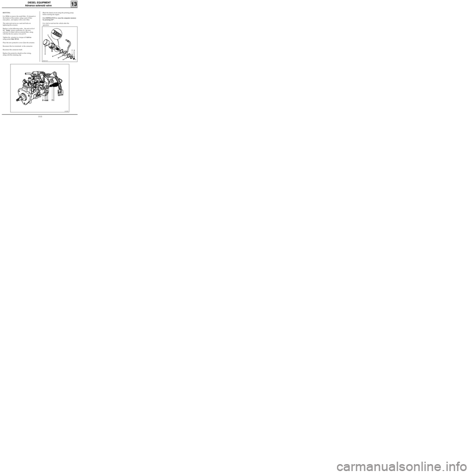
It is VITAL to remove the small filter (3) situated at
the bottom of the system, using a pair of thin-
nose pliers, and replace with a new filter.
The outer part serves as a seal and locks on
tightening the actuator.
Replace, in the following order : the seal at (4) of
the "banjo" return connection (5) ; the new
activator (1) fitted with an external filter, along
with the the two seals at (6) and (7).
Tighten the actuator to a torque of 3 daN.m
using socket Mot. 997-01.
Place the new protective cover (2)on the actuator.
Reconnect the two terminals to the connector.
Reconnect the connector itself.
Replace the protective sheath on the wiring,
along with the retaining clip.Bleed the diesel circuit using the priming pump
before starting the engine.
It is IMPERATIVE to erase the computer memory
by pressing G0**.
It is vital to road test the vehicle after the
operation.
13127R
13-21
Page 102 of 208
DIESEL EQUIPMENT
Altimetric corrector
13
13129R
SPECIAL TOOLING REQUIRED
Mot. 997-01 Tool for removing injector
Mot. 1140 Tool for removing altimetric
corrector
Altimetric corrector 3
TIGHTENING TORQUES (in daN.m)
REMOVAL
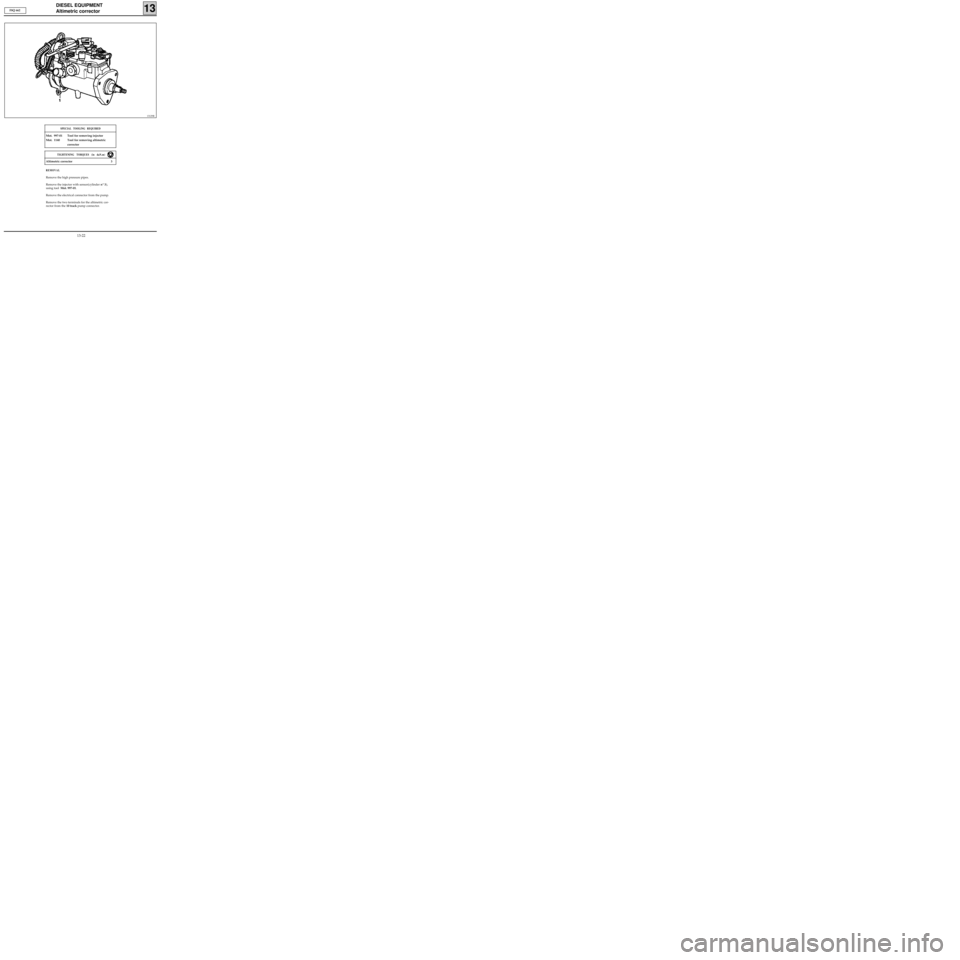
Remove the high pressure pipes.
Remove the injector with sensor(cylinder n° 3),
using tool Mot. 997-01.
Remove the electrical connector from the pump.
Remove the two terminals for the altimetric cor-
rector from the 10 track pump connector. F8Q 662
13-22