torque RENAULT KANGOO 1997 KC / 1.G Engine And Peripherals Repair Manual
[x] Cancel search | Manufacturer: RENAULT, Model Year: 1997, Model line: KANGOO, Model: RENAULT KANGOO 1997 KC / 1.GPages: 208
Page 160 of 208

INJECTION
Location of components
17
12 Coolant temperature sensor8 Injection computer
9 Inertia switch
13240R
3 Pinking sensor
(tightening torque: 2.5 daN.m)
13336R13239R
E7J Engine
17-10
Page 161 of 208
INJECTION
Location of components
17
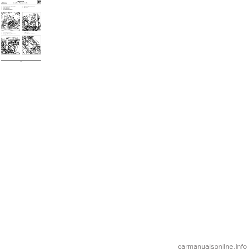
4 Absolute pressure sensor
5 Idle speed regulation stepping motor
7 Air temperature sensor6 Throttle position potentiometer
11 TDC sensor
13337R
1 Fuel vapour recycling solenoid valve
14 Coil for cylinders 2-3
16 Coil for cylinders 1-4
18 Anti-interference condenser
13242R1
13339R
13 Oxygen sensor
(tightening torque : 4.5 daN.m)
13243R
E7J Engine
17-11
Page 167 of 208
INJECTION
Injection/air conditioning programming
17
THIS VEHICLE IS FITTED WITH A VARIABLE OUTPUT COMPRESSOR
AIR CONDITIONING/INJECTION COMPUTER CONNECTION
The electrical connection :
- between the air conditioning computer and the injection computer consists of a single wire (track 5).
This track carries two types of information :
-the fast idle speed request information . For this information to be transmitted to the injection
computer , two conditions must be fulfilled :
• the air conditioning function must have been selected on the control panel ,
• the pressure in the air conditioning circuit must be greater than a certain threshold.
If this information is transmitted, the fast idle speed is obtained (it is therefore normal that
sometimes, when the air conditioning is switched on, engine idling, there is no fast idle speed ).
-the Absorbed Power information. This information has no influence on the idle speed. It simply
informs the injection computer of the torque value taken up by the compressor; the computer, in
turn, acts on the idle speed regulation solenoid. The absorbed power may be visualised using the
XR25. When the air conditioning is switched on , #44 should be between 300 and 5 000 watts.
IMPORTANT: the value at #44 or idle speed is never equal to 0, whatever the status of the
compressor, off or on . The minimum value which may be read using #44 is approximately 300
watts.
- between the the injection computer and the air conditioning computer consists of a single wire (track
51). This track carries the information regarding the authorisation or prevention of compressor
operation.
COMPRESSOR OPERATION PROGRAMMING
During certain operating phases, the injection computer prevents the compressor from operating.
Programming when starting engine
The compressor is prevented from functioning for 10 seconds after starting the engine .
Recovery of performance ( D7F engine)
Depending on the torque required by the driver and on the power absorbed by the air conditioning
compressor, the injection computer stops or allows the operation of the compressor .
Anti-stalling function (D7F engine)
If the no load position is recognised , and the engine speed is lower than 600 rpm, and if the power absorbed
by the compressor is greater than 300 watts, the compressor disengages .
It engages again if:
- the no load position is recognised when the engine speed reaches 850 rpm.,
- if the no load position is not recognised when the engine speed reaches 1 800 rpm.
Thermal protection programming ( E7J engine )
The compressor does not engage in cases where the coolant temperature is greater than or equal to +
115°C.
Over-revving protection (E7J engine )
The compressor is prevented from operating if the engine speed is greater than 5 900 rpm.
17-17
Page 181 of 208
COOLING
Water pump
CLEANING
It is very important not to scratch the gasket faces
of all aluminium components.
Use the product Décapjoint to dissolve the part
of the gasket which remains attached.
Apply the product to the part to be cleaned, wait
approximately 10 minutes, then remove it using a
wooden spatula.
The wearing of gloves is recommended during
this operation.
19
SPECIAL TOOLING REQUIRED
Mot. 1054TDC pin
Mot. 1202 Hose clip pliers
Mot. 1273 Tool for checking belt tension
Mot. 1289-03 Tool for centring the suspended en-
gine movement limiter
Mot. 1379 Tool for retaining engine on sub-
frame
10478S
D7F Engine
Crankshaft output mounting bolts 2 + 90°
Bolt for mounting front right suspended
engine mounting on engine 6.2
Bolt for mounting front right suspended
engine mounting on vehicle body 6.2
Timing belt tension wheel nut 5
Water pump mounting bolt 0.9
TIGHTENING TORQUES (in daN.m)
REMOVAL
Place the vehicle on a two post lift.
Disconnect the battery.
Remove:
- the timing belt (see method described in
section 11 "Timing belt),
- the power assisted steering pump pulley (if fit-
ted),
- the upper alternator mounting bolt and
slacken the lower bolt,
- the bolts for mounting the power assisted
steering pipe on the cylinder block,
- the bolts for mounting the power assisted
steering pump on its support (move the po-
wer assisted steering pump-pipe assembly to
one side),
- the power assisted steering pump support,
- the water pump hose,
- the tension wheel along with the water pump
itself.
19-7
Page 183 of 208
COOLING
Water pump
Refit the timing belt (see method described in
chapter 11 "Timing belt").
Fill and bleed the cooling circuit (see section 19
"Filling - Bleeding").
19
SPECIAL TOOLING REQUIRED
Mot. 591-02 Index
Mot. 591-04 Angle tightening wrench
Mot. 1135-01 Tool for tensioning the timing belt
Mot. 1202 Hose clip pliers
Mot. 1273 Tool for checking belt tension
92068R
E7J Engine
Tension wheel nut 5
Crankshaft pulley bolt 2 + 68° + 6°
Bolt for suspended engine mounting cover 6,2
Nut for suspended engine mounting cover 4,4
Water pump bolt 2,2
Water pump nut 1
Wheel bolts 9
TIGHTENING TORQUES (in daN.m)
EQUIPMENT REQUIRED
Engine support tool
REFITTING
The sealing of the water pump is carried out using
the product
LOCTITE 518; the bead (H) must be
applied following the diagram below.
REMOVAL
Place the vehicle on a two post lift.
Disconnect the battery.
Drain the cooling circuit from the lower radiator
hose.
Remove:
- the timing belt (see method described in
section 11 "Timing belt),
- the timing tension wheel,
- the water pump, and extract this from above.
CLEANING
It is very important not to scratch the gasket faces
of all aluminium components.
Use the product Décapjoint to dissolve the part
of the gasket which remains attached.
Apply the product to the part to be cleaned, wait
approximately 10 minutes, then remove it using a
wooden spatula.
The wearing of gloves is recommended during
this operation.
19-9
Page 184 of 208
COOLING
Water pump
19
SPECIAL TOOLING REQUIRED
Mot. 1202 Hose clip pliers
13090R
F8Q Engine
Water pump bolt 1.6
Bolt for water pump pulley 2
Bolt for crankshaft pulley 2 + 115° ± 15°
TIGHTENING TORQUES (in daN.m)
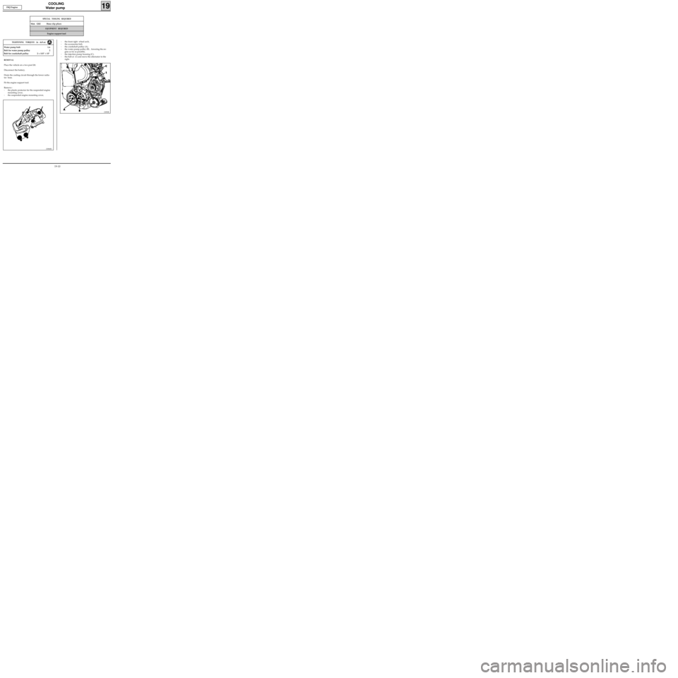
REMOVAL
Place the vehicle on a two post lift.
Disconnect the battery.
Drain the cooling circuit through the lower radia-
tor hose.
Fit the engine support tool.
Remove :
- the plastic protector for the suspended engine
mounting cover,
- the suspended engine mounting cover,
EQUIPMENT REQUIRED
Engine support tool
- the front right wheel arch,
- the accessories belt,
- the crankshaft pulley (A),
- the water pump pulley (B) , lowering the en-
gine as far as possible,
- the injection pump housing (C),
- the bolt at (1) and move the alternator to the
right.
13086R1
19-10
Page 188 of 208
EXHAUST
General
19
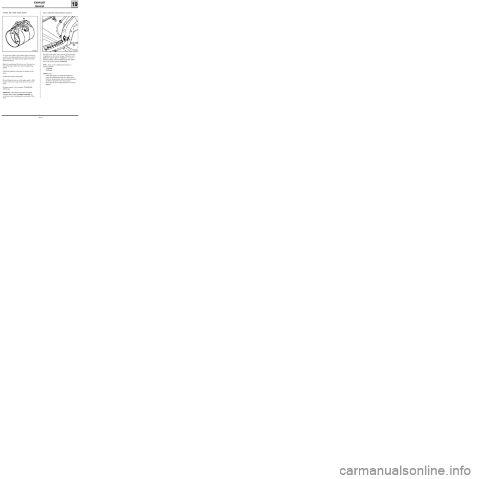
FITTING THE AFTER SALES SLEEVE
95478R1
Once a collar has been used once, renew it.
The nut on the collar has a groove (A) to ensure it
is tightened to the correct torque. When the nut is
tightened and the groove disappears, it causes a
distinct clicking sound and the nut is then tighte-
ned to the correct torque (2.5 daN.m).
NOTE : there are two different diameters of
sleeve available:
-∅ 50 mm,
-∅ 45 mm .
IMPORTANT:
- check that there is no point of contact bet-
ween the exhaust pipe and the vehicle body,
- check for the presence and correct positioning
of all heat shields for the exhaust pipe,
- check that the two cutting marks are correctly
aligned.
99227S
To avoid any leaks in the exhaust pipe, the sleeve
must be correctly positioned over the two exhaust
pipe sections. The pipe must be against the stops
inside the sleeve.
Begin by positioning the sleeve over the used sec-
tion of the pipe, adjust the collar by tightening
gently.
Check the position of the pipe in relation to the
stops.
Fit the new section of the pipe.
Before fitting the sleeve on the pipe, apply a little
mastic to the inner ring on the sleeve to prevent
leaks.
(Exhaust mastic, Part Number. 77 01 421 161
SODICAM).
IMPORTANT : the bolt and nut used for tighte-
ning the sleeve must be aligned vertically to
avoid any risks of touching the underside of the
body.
19-14
Page 191 of 208
Mot. 1199-01 Exhaust pipe cutting tool
Mot. 1265
Mot. 1265-01
FUEL TANK
Fuel tank
19
IMPORTANT : during all the fuel tank removal
and refitting operations, refrain from smoking
and be sure not to handle incandescent objects in
the vicinity of the working area.
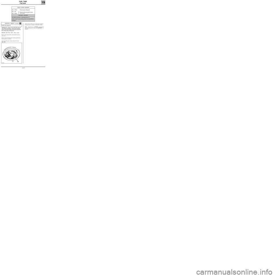
DRAINING THE FUEL TANK (Petrol version)
Remove the pump-sender unit assembly steel ac-
cess cover.
Remove the clip which shows if the assembly has
been pushed in (if fitted).
Disconnect the quick release union at (1), tool
Mot. 1265.
EQUIPMENT REQUIRED
INTAIRCO pneumatic siphoning pump, for
petrol or diesel tank draining system (see EQUIPMENT
catalogue).
SPECIAL TOOLING REQUIRED
97163R2
Attach to the outlet at (A), a pipe long enough to
be placed into a container outside the vehicle .
NOTE : Alternatively, an INTAIRCO pneumatic si-
phoning pump may be used (see
EQUIPMENT ca-
talogue). Sender unit- pump nut 7
TIGHTENING TORQUES (in daN.m)
Pliers for removing quick release
fuel unions
19-17
Page 204 of 208
Mot. 1264 Wrench for removing
Mot. 1264-01 pump-sender unit assembly nut
Mot. 1265 Pliers for removing
Mot. 1265-01 quick release unions
FUEL TANK
Pump- sender unit
19
SPECIAL TOOLING REQUIRED
IMPORTANT :
During all operations on the fuel tank or on the
fuel supply circuit , it is vital :
- to refrain from smoking and handling incan-
descent objects in the vicinity of the working
area,
- to avoid fuel projections, due to the residual
pressure present in the pipes during removal .
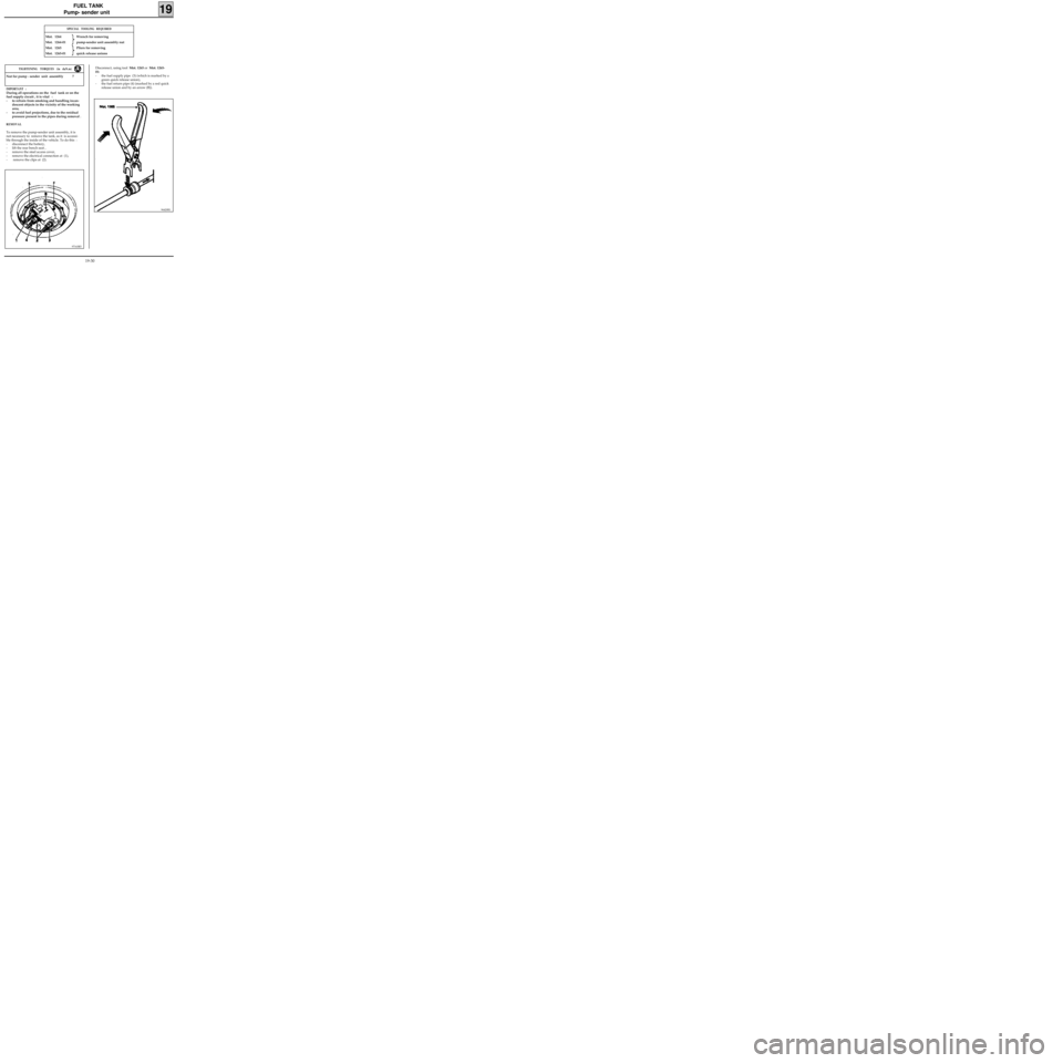
REMOVAL
To remove the pump-sender unit assembly, it is
not necessary to remove the tank, as it is accessi-
ble through the inside of the vehicle. To do this :
- disconnect the battery,
- lift the rear bench seat ,
- remove the steel access cover,
- remove the electrical connection at (1),
- remove the clips at (2).
97163R5
Nut for pump - sender unit assembly 7
TIGHTENING TORQUES (in daN.m)Disconnect, using tool Mot. 1265 or Mot. 1265-
01:
- the fuel supply pipe (3) (which is marked by a
green quick release union),
- the fuel return pipe (4) (marked by a red quick
release union and by an arrow (B)).
96420R1
19-30
Page 205 of 208
FUEL TANK
Pump- sender unit
19
REFITTING
Check that the seal is not deformed, and replace it
if necessary.
Position the pump-sender unit assembly
(ensuring that the arrow at (F) is placed in the
longitudinal axis of the vehicle pointing to the
rear).
Position the nut and tighten it to the torque of
3.5 daN.m.
Fit the fuel pipes (it is not necessary to use the
pliers Mot. 1265 or Mot. 1265-01).
Refit the safety clips at (2).
Reconnect the electrical connection.
Refit the steel cover.
ALLOCATION OF CONNECTOR TRACKS
TRACK ALLOCATION
A1 Earth
A2 Fuel minimum level warning light
B1 Sender unit information to instrument
panel
B2 Not used
C1 pump
C2 pump
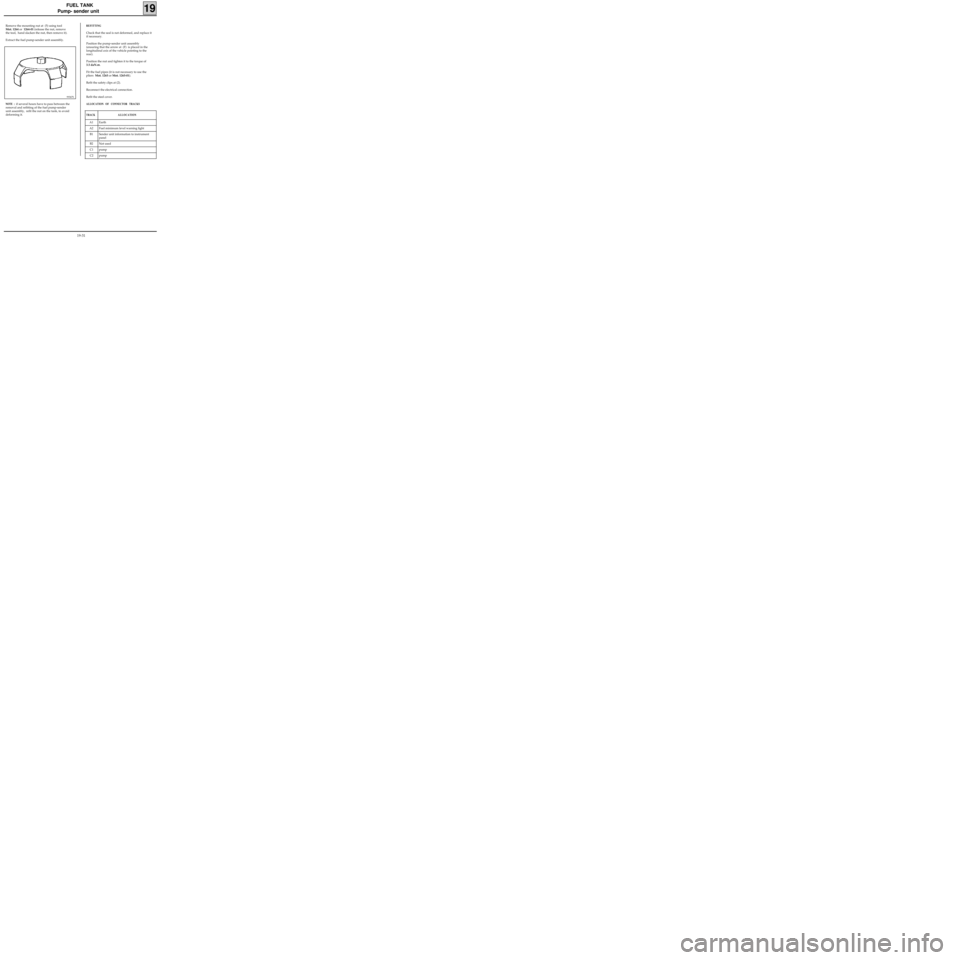
Remove the mounting nut at (5) using tool
Mot. 1264 or 1264-01 (release the nut, remove
the tool, hand slacken the nut, then remove it).
Extract the fuel pump-sender unit assembly.
99367S
NOTE : if several hours have to pass between the
removal and refitting of the fuel pump-sender
unit assembly, refit the nut on the tank, to avoid
deforming it.
19-31