sensor RENAULT KANGOO 1997 KC / 1.G Engine And Peripherals Service Manual
[x] Cancel search | Manufacturer: RENAULT, Model Year: 1997, Model line: KANGOO, Model: RENAULT KANGOO 1997 KC / 1.GPages: 208
Page 170 of 208

OXYGEN SENSOR VOLTAGE (#05)
Reading #05 on the XR25 : the value read is the voltage sent to the computer by the oxygen sensor; it is ex-
pressed in volts (the value actually varies between 0 and 1 000 millivolts).
When the engine is in the loop phase, the voltage value should oscillate rapidly and should be between
50±50 mV (lean mixture) and 850 ± 50 mV (rich mixture) and vice versa.
The smaller the gap between the upper and lower values, the poorer the information from the sensor (the
gap is usually at least 500 mV).
RICHNESS CORRECTION (#35)
The value given under # 35 on the XR25 represents the average value of richness corrections made by the
computer depending on the richness of the burnt mixture as seen by the oxygen sensor (the oxygen sensor ac-
tually analyses the oxygen content of the exhaust gases directly from the richness of the burnt mixture).
The richness correction has a centre point of 128 with thresholds of 0 and 255 (experience has shown that un-
der normal operating conditions # 35 is located close to 128 with only a small amount of variation).
- Value less than 128 : request for mixture to be made leaner.
- Value greater than 128 : request for mixture to be made richer.
ENTRY INTO RICHNESS REGULATION MODE
Loop phase
Richness regulation begins after the timed starting period :
- for no load, if the coolant temperature has reached :
•46°C for the E7J engine ,
•30°C for the D7F engine.
- outside no load conditions if the coolant temperature is greater than :
•+ 20°C for the E7J, engine
•+ 20°C for the D7F engine.
The timed starting period is dependent on the coolant temperature :
- at 20°C it is a maximum of :
•3 minutes for the E7J engine,
•1 minute 20 seconds for the D7F engine,
- at 80°C it is a maximum of :
•1 minute 30 seconds for the E7J engine,
•35 seconds for the D7F engine,
If richness regulation has not yet started, #35 = 128
INJECTION
Richness regulation
17
17-20
Page 171 of 208

INJECTION
Richness regulation
17
Non-loop mode
When richness regulation is occurring, the operating phases when the computer ignores the voltage informa-
tion from the oxygen sensor are:
- Full load: #35 = variable and greater than 128
- Sharp acceleration: #35 = variable and greater than 128
- Deceleration with no load information (injection cut) : #35 = 128
- Oxygen sensor fault: #35 = 128
DEFECT MODE IN THE EVENT OF AN OXYGEN SENSOR FAULT
If the voltage from the oxygen sensor is incorrect (# 05 varies only slightly or not at all) during richness regu-
lation, the computer will only enter defect mode (# 35 = 128) if the fault has been present for 3 to 5 minutes.
The fault will be memorised in this case only.
If an oxygen sensor fault is present and recognised and if the fault has already been stored, the system enters
the open loop mode directly (# 35 = 128)
17-21
Page 202 of 208

FUEL TANK
Fuel tank
19
PURPOSE OF THE VALVES
28 Overfill prevention valve
When the filler cap is removed the valve is
closed, trapping a volume of air within the
breather volume. This prevents fuel from fil-
ling this volume.
When the filler cap is replaced, the valve
opens allowing the tank to breathe through
the canister
29 Excess - vacuum safety valve
If the fuel vapour recirculation circuit is
blocked, this valve prevents the fuel tank
being subject to excess pressure (the tank
would inflate) or vacuum (as fuel is used, the
tank would be crushed).
30 Restriction valve
This valve prevents the introduction of leaded
fuel into the tank.
31 Leak prevention valve in case vehicle turns
over
If the vehicle turns over, this valve prevents
the tank from emptying, either through the
pipe leading to the canister, or through the
breather pipe (in Diesel versions).
32 Overfill prevention valve and leak prevention
valve in case the vehicle turns over
The overfill prevention valve operates using
the ball at (33).
When the vehicle is stationary, during filling,
the ball rests in its seat, retaining a certain
volume of air in the reservoir .
When the vehicle is moving , the ball (33)
moves out of its seat, thus allowing the tank
to be connected to the canister.
When the tank is full, it is vital that a
sufficient volume of air to allow the fuel
contained within it to expand is retained
inside the tank, but not too much, otherwise
there is a risk of the tank exploding .
This valve has the same operating principle as
the valve (31) .
The tank has a sealed cap.
The filler neck for unleaded petrol has the follo-
wing special features :
- a filling opening with a smaller diameter and
not compatible with a conventional filling
nozzle (the lead would have the effect of pol-
luting the depollution system: oxygen sensor
and catalytic converter),
- a valve blocking the filing opening (30) (to
avoid fuel evaporating or the reverse passage
of fuel).
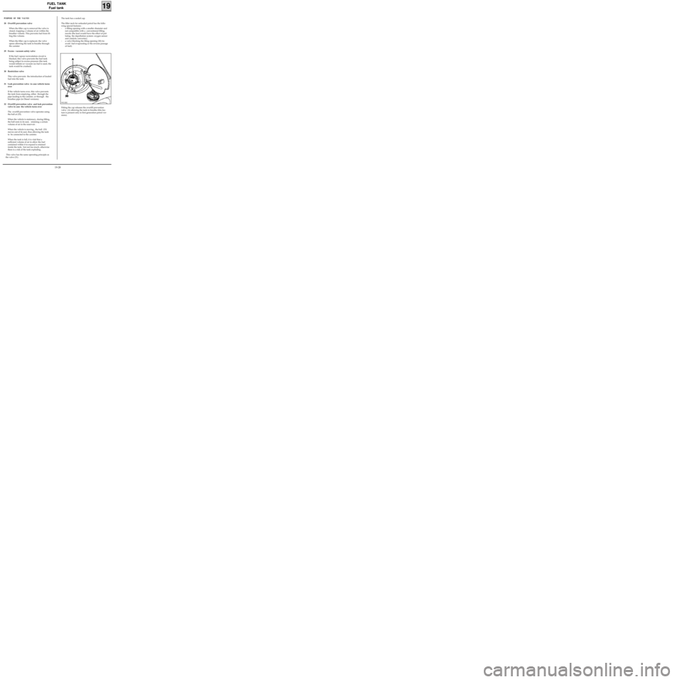
Fitting the cap releases the overfill prevention
valve (A) allowing the tank to breathe (this fea-
ture is present only in first generation petrol ver-
sions).
99212R2
19-28