air condition RENAULT KANGOO 1997 KC / 1.G Engine And Peripherals Workshop Manual
[x] Cancel search | Manufacturer: RENAULT, Model Year: 1997, Model line: KANGOO, Model: RENAULT KANGOO 1997 KC / 1.GPages: 208
Page 3 of 208

Contents
Consumables
Identification
Oil consumption
Oil pressure
Engine - Gearbox
Engine and transmission assembly
Sump
Crankshaft seal, timing end
Oil pump10-1
10-1
10-2
10-3
10-4
10-9
10-25
10-29
10-30
TOP AND FRONT OF ENGINE
Timing belt
Cylinder head gasket
Replacement of valve adjustersPage Page
11
Engine and
peripherals
11-1
11-11
11-29 ENGINE AND PERIPHERALS
10FUEL SUPPLY -
DIESEL EQUIPMENT
Fuel supply
Fuel cut off in case of an impact
Injector gallery
Fuel filter
Pump flow
Fuel pressure
Antipercolation device
Diesel equipment
General
Specifications
Location of components
Advance solenoid valve
Altimetric corrector
Fast idle LDA
Coded solenoid valve
Load potentiometer
Computer configuration
Injector with sensor (needle
lift)
Injection warning light
Pre-postheating control
Fast idle control
Injection/air conditioning
programming
Computer
Defect modes
Pump
Pump -Timing
Idle speed settings13-1
13-2
13-6
13-7
13-8
13-12
13-13
13-14
13-16
13-19
13-22
13-25
13-26
13-28
13-29
13-31
13-32
13-33
13-35
13-36
13-36
13-37
13-38
13-39
13-41
13-4613
FUEL MIXTURE
Specifications
Throttle body
Inlet manifold
Exhaust manifold
Inlet-exhaust manifolds12-1
12-7
12-15
12-18
12-2012
Page 4 of 208

Page
Cooling
Specifications
Filling and bleeding
Testing
Diagram
Water pump
Exhaust
General
Exhaust pipe assembly
Fuel tank
Tank
Sender unit
Pump and sender unit assembly
Engine suspension
Suspended engine mountings19-1
19-2
19-3
19-4
19-7
19-12
19-15
19-17
19-29
19-30
19-32 COOLING - EXHAUST - FUEL TANK -
ENGINE SUSPENSION
19
16-1
16-7 STARTING - CHARGING
Alternator
Starter
16
IGNITION - INJECTION
Ignition
Static ignition
Plugs
Injection
General
Location of components
Centralised coolant temperature
management
Injection fault warning light
Immobiliser function
Computer configuration depending
on gearbox type17
14-1
14-2
14-7
14-11 ANTIPOLLUTION
Test for the presence of lead
Fuel vapour rebreathing
Oil vapour rebreathing
Exhaust gas recirculation
(EGR)
14
17-17
17-18
17-19
17-20
17-22 IGNITION - INJECTION
(continued)
Injection/air conditioning
programming
Idle speed correction
Adaptive idle speed
correction
Richness regulation
Adaptive richness correction
17
Page
17-1
17-3
17-4
17-8
17-13
17-14
17-15
17-16
Contents
Page 67 of 208
FUEL MIXTURE
Specifications
12
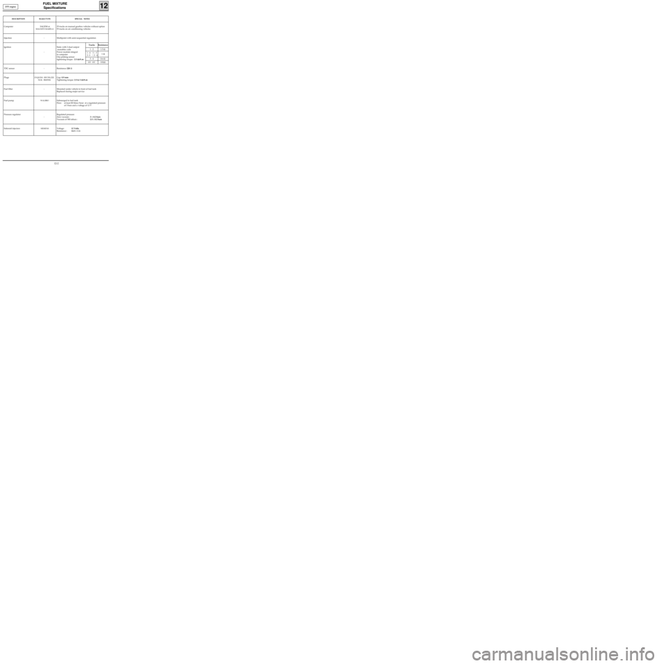
DESCRIPTIONMAKE/TYPESPECIAL NOTES
Computer SAGEM or
MAGNÉTI MARÉLLI
35 tracks on manual gearbox vehicles without option
55 tracks on air conditioning vehicles
Injection - Multipoint with semi-sequential regulation
Ignition
-Static with 2 dual output
monobloc coils
Power module integral
in computer
One pinking sensor
tightening torque : 2.5 daN.m
TDC sensor - Resistance 220 Ω
Plugs
EYQUEM : RFC50LZ2E
NGK : BKR5EKGap: 0.9 mm
Tightening torque: 2.5 to 3 daN.m
Fuel filter - Mounted under vehicle in front of fuel tank
Replaced during major service
Fuel pump
WALBROSubmerged in fuel tank
Flow: at least 80 litres/hour at a regulated pressure
of 3 bars and a voltage of 12 V
Pressure regulator
-Regulated pressure
Zero vacuum :3 ± 0.2 bars
Vacuum of 500 mbars :2.5 ± 0.2 bars
Solenoid injectors
SIEMENSVoltage:12 Volts
Resistance :14.5 ± 1 Ω
Tracks Resistance
1 - 2 1.5 Ω
1
- 4 |1 - 3
2 -3 | 2 - 41 Ω
3 - 4 0.6 Ω
HT - HT8 KΩ
D7F engine
12-2
Page 109 of 208
DIESEL EQUIPMENT
Computer configuration
13
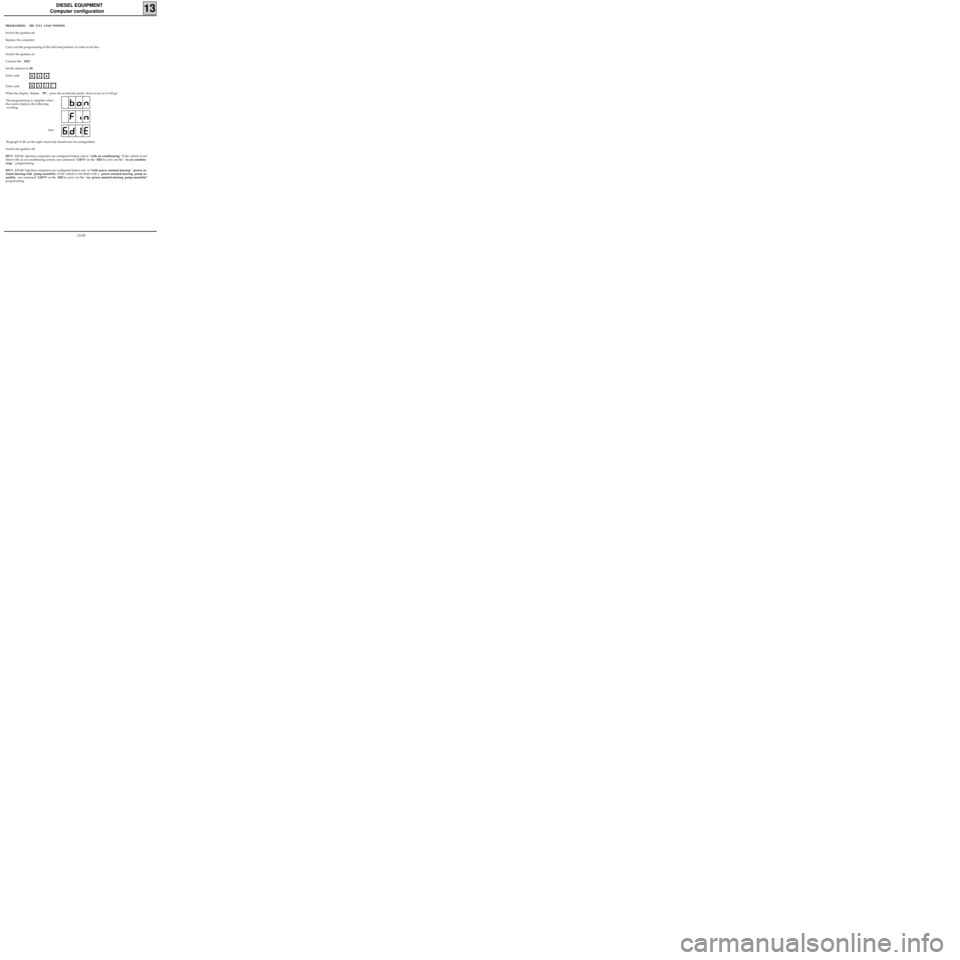
PROGRAMMING THE FULL LOAD POSITION
Switch the ignition off.
Replace the computer.
Carry out the programming of the full load position; in order to do this :
Switch the ignition on.
Connect the
XR25.
Set the selector to S8.
Enter code
Enter code
When the display flashes "PF", press the accelerator pedal down as far as it will go.
The programming is complete when
the screen displays the following
wording: D
34
G31*
Bargraph N.12 on the right hand side should now be extinguished.
Switch the ignition off.
DPCN LUCAS injection computers are configured before sale to "with air conditioning". If the vehicle is not
fitted with an air conditioning system, use command G50*4* on the
XR25 to carry out the "no air conditio-
ning " programming.
DPCN LUCAS "injection computers are configured before sale to "with power assisted steering " (power as-
sisted steering with pump assembly). If the vehicle is not fitted with a power assisted steering pump as-
sembly, use command G50*9* on the
XR25 to carry out the "no power assisted steering pump assembly"
programming.then
13-29
Page 110 of 208
DIESEL EQUIPMENT
Computer configuration
13
COMPUTER CONFIGURATION IN RELATION TO AIR CONDITIONING.
For vehicles equipped with air conditioning , enter G50*3* on the XR25
For vehicles without air conditioning , enter G50*4* on the XR25 .
COMPUTER CONFIGURATION IN RELATION TO THE PAS (POWER ASSISTED STEERING PUMP ASSEMBLY)
The vehicle may have two types of PAS assembly :
-a
PAS assembly including a high pressure pump driven by a belt. In this case, the computer must be
configured without PAS : enter G50*9* on the
XR25,
-a
PAS assembly with a pump assembly which is driven electrically and controlled by the injection compu-
ter. ( this type of
PAS is fitted in all vehicles which are also equipped with AC). In this case, the computer
must be configured with PAS : enter G50*8* on the XR25.
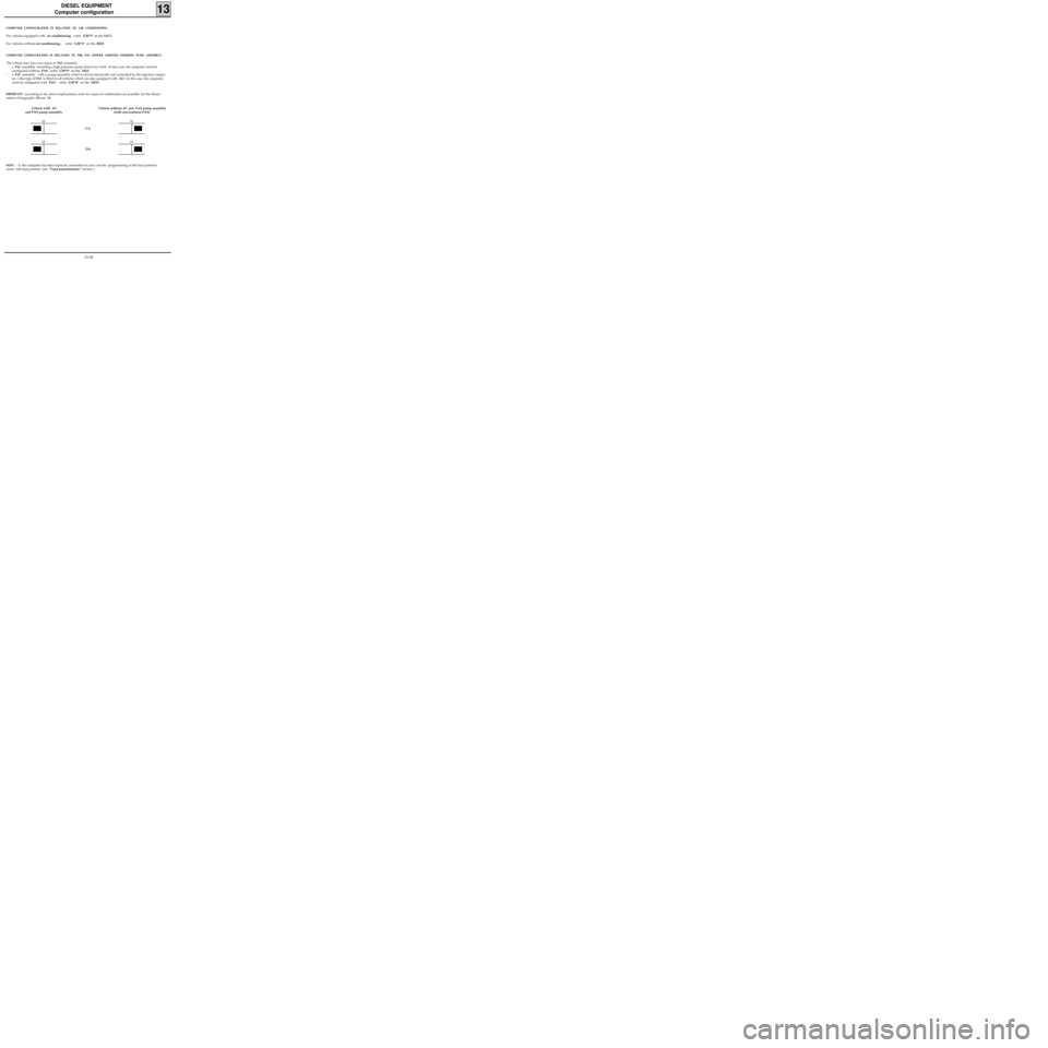
IMPORTANT : according to the above explanations, only two types of combination are possible for the illumi-
nation of bargraphs 18 and 19.
Vehicle with AC
and PAS pump assemblyVehicle without AC and PAS pump assembly
(with conventional PAS)
18
19
18
19
DA CA
NOTE : if the computer has been replaced, remember to carry out the programming of the load potentio-
meter full load position (see "Load potentiometer " section ).
13-30
Page 116 of 208
DIESEL EQUIPMENT
Injection/air conditioning programming
13
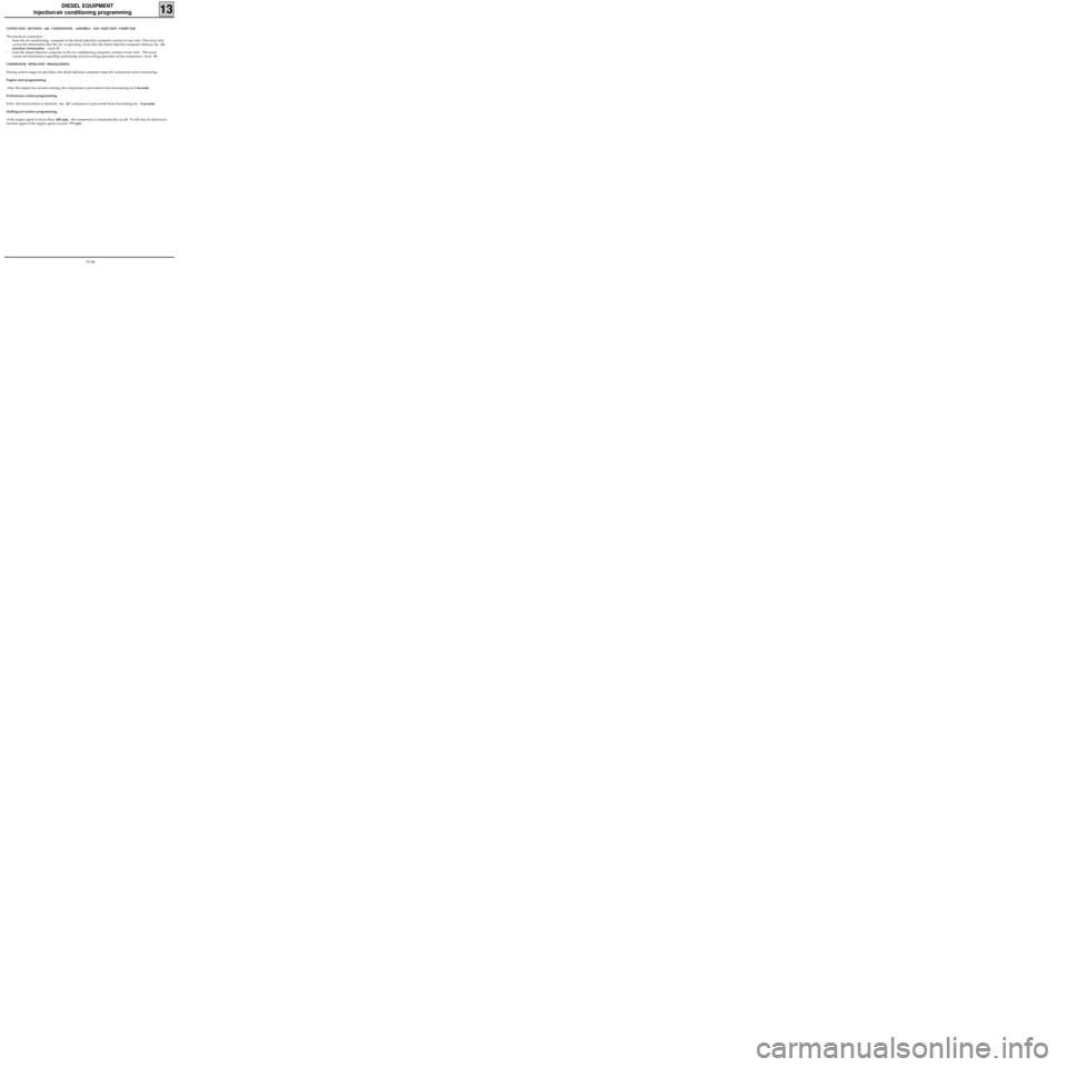
CONNECTION BETWEEN AIR CONDITIONING ASSEMBLY AND INJECTION COMPUTER
The electrical connection :
- from the air conditioning computer to the diesel injection computer consists of one wire. This track only
carries the information that the AC is operating. From this, the diesel injection computer deduces the AC
selection information : track 11,
- from the diesel injection computer to the air conditioning computer consists of one wire. This track
carries all information regarding authorising and preventing operation of the compressor : track 19.
COMPRESSOR OPERATION PROGRAMMING
During certain stages of operation, the diesel injection computer stops the compressor from functioning.
Engine start programming
After the engine has started running, the compressor is prevented from functioning for 3 seconds.
Performance return programming
If the full load position is detected, the AC compressor is prevented from functioning for 8 seconds.
Stalling prevention programming
If the engine speed is lower than 650 rpm., the compressor is automatically cut off. It will only be allowed to
function again if the engine speed exceeds 775 rpm.
13-36
Page 130 of 208
ANTIPOLLUTION
Fuel vapour rebreathing
14
CONDITION FOR BLEEDING THE CANISTER ( D7F
engine)
• Coolant temperature greater than+ 15 °C
•Air temperature greater than +10 °C.
• No load position not recognised (if there is a
fault in the throttle potentiometer sensor, the
condition of no load position not recognised is
replaced by an engine speed condition
R > 1500 rpm.).
It is possible to visualise the cyclical opening ratio
for the canister bleed solenoid using the
XR25
and #23. The solenoid is closed if #23 = 0.7 %
CONDITION FOR BLEEDING THE CANISTER (E7J
engine)
During richness regulation
Coolant temperature greater than 50°C.
Air temperature greater than 15°C.
No load position not recognised (if there is a fault
in the throttle potentiometer sensor, the
condition of no load position not recognised is
replaced by an engine speed condition
R > 1500 rpm.).
Outside richness regulation
•Coolant temperature greater than 50°C.
•Air temperature greater than 15°C.
•Full load position recognised (function of
engine speed and manifold pressure).
If there is a fault in the oxygen sensor, bleeding is
permitted outside of no load conditions.
It is possible to visualise the cyclical opening ratio
for the canister bleed solenoid using the
XR25
and #23. The solenoid is closed if #23 = 0.7 %
(minimum value).
14-4
Page 131 of 208
ANTIPOLLUTION
Fuel vapour rebreathing
14
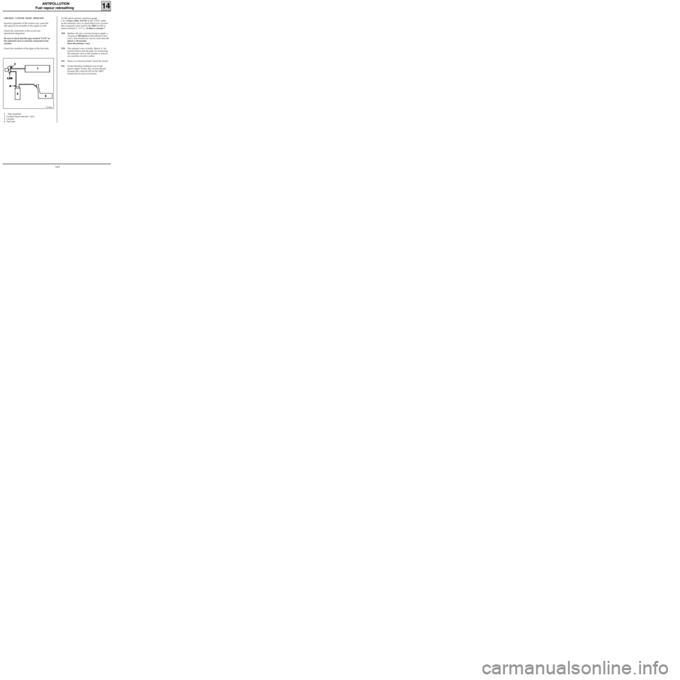
CHECKING CANISTER BLEED OPERATION
Incorrect operation of the system may cause the
idle speed to be unstable or the engine to stall.
Check the conformity of the circuit (see
operational diagrams)
Be sure to check that the pipe marked "CAN" on
the solenoid valve is correctly connected to the
canister.
Check the condition of the pipes to the fuel tank.
97393R6
1Inlet manifold
2Canister bleed solenoid valve
3Canister
4Fuel tankAt idle speed connect a pressure gauge
(- 3 ; +3 bars) (Mot. 1311-01) to the "CAN" outlet
on the solenoid valve, to check there is no vacuum
(the command value read by the
XR25 for #23 re-
mains minimal X = 0.7 % ). Is there a vacuum ?
YESIgnition off, use a vacuum pump to apply a
vacuum of 500 mbars to the solenoid valve
at (C). This should not vary by more than 10
mbars in 30 seconds.
Does the pressure vary?
YESThe solenoid valve is faulty. Renew it. Air
must be blown into the pipe (A) connecting
the solenoid valve to the canister to remove
any particles of active carbon.
NOThere is an electrical fault. Check the circuit.
NOUnder bleeding conditions (not at idle
speed, engine warm), the vacuum should
increase (the value for #23 on the XR25
should also be seen to increase).
14-5
Page 154 of 208
INJECTION
General
17
SPECIAL NOTES FOR MULTIPOINT INJECTION
• 35 track SAGEM or MAGNETI MARELLI computer for vehicles without options.
• 55 track SAGEM computer ,
SAFIR or MAGNETI MARELLI type for versions with air conditioning.
•Semi-sequential multipoint injection. Injectors controlled two by two (injectors for cylinders 1 and 4 fol-
lowed by injectors for cylinders 2 and 3).
•Semi-static ignition with dual single unit coils.
•Canister bleed solenoid valve controlled by RCO signal.
•Computer configuration depending on gearbox type (manual gearbox or automatic transmission).
•The maximum engine speed permitted is 6 200 rpm.
•Idle speed correction depending on :
- battery voltage,
- air conditioning
- power assisted steering pressostat.
•Injection warning light on instrument panel not operational.
•Use fault finding fiche n° 27. D7F Engine
FITTING A 2ND GENERATION ENGINE IMMOBILISER REQUIRES A SPECIAL PROCEDURE FOR REPLACING THE
COMPUTER.
17-4
Page 155 of 208
INJECTION
General
17
SPECIAL NOTES FOR MULTIPOINT INJECTION
• 55 track SIEMENS FENIX 5 computer.
•Semi-sequential multipoint injection. Injectors are controlled two by two (injectors for cylinders 1 and 4
followed by cylinders 2 and 3).
•Semi-static ignition with dual coils.
•Canister bleed solenoid controlled by RCO signal.
•Computer configuration depending on gearbox type (manual gearbox or automatic transmission)
•Idle speed correction depending on :
- air conditioning,
- power assisted steering pressostat,
- battery voltage.
•Injection warning light on instrument panel operational.
•Use fault finding fiche n° 27.
•Maximum speed :
-6 200 rpm if 1st , 2nd or 3rd gears
-6 000 rpm if 4th,or 5th gears. E7J Engine
FITTING A 2ND GENERATION ENGINE IMMOBILISER REQUIRES A SPECIAL PROCEDURE FOR REPLACING THE
COMPUTER.
17-5