air filter RENAULT KANGOO 1997 KC / 1.G Engine And Peripherals Workshop Manual
[x] Cancel search | Manufacturer: RENAULT, Model Year: 1997, Model line: KANGOO, Model: RENAULT KANGOO 1997 KC / 1.GPages: 208
Page 3 of 208
Contents
Consumables
Identification
Oil consumption
Oil pressure
Engine - Gearbox
Engine and transmission assembly
Sump
Crankshaft seal, timing end
Oil pump10-1
10-1
10-2
10-3
10-4
10-9
10-25
10-29
10-30
TOP AND FRONT OF ENGINE
Timing belt
Cylinder head gasket
Replacement of valve adjustersPage Page
11
Engine and
peripherals
11-1
11-11
11-29 ENGINE AND PERIPHERALS
10FUEL SUPPLY -
DIESEL EQUIPMENT
Fuel supply
Fuel cut off in case of an impact
Injector gallery
Fuel filter
Pump flow
Fuel pressure
Antipercolation device
Diesel equipment
General
Specifications
Location of components
Advance solenoid valve
Altimetric corrector
Fast idle LDA
Coded solenoid valve
Load potentiometer
Computer configuration
Injector with sensor (needle
lift)
Injection warning light
Pre-postheating control
Fast idle control
Injection/air conditioning
programming
Computer
Defect modes
Pump
Pump -Timing
Idle speed settings13-1
13-2
13-6
13-7
13-8
13-12
13-13
13-14
13-16
13-19
13-22
13-25
13-26
13-28
13-29
13-31
13-32
13-33
13-35
13-36
13-36
13-37
13-38
13-39
13-41
13-4613
FUEL MIXTURE
Specifications
Throttle body
Inlet manifold
Exhaust manifold
Inlet-exhaust manifolds12-1
12-7
12-15
12-18
12-2012
Page 19 of 208
ENGINE AND ENGINE PERIPHERALS
Engine and transmission assembly
10
13085R
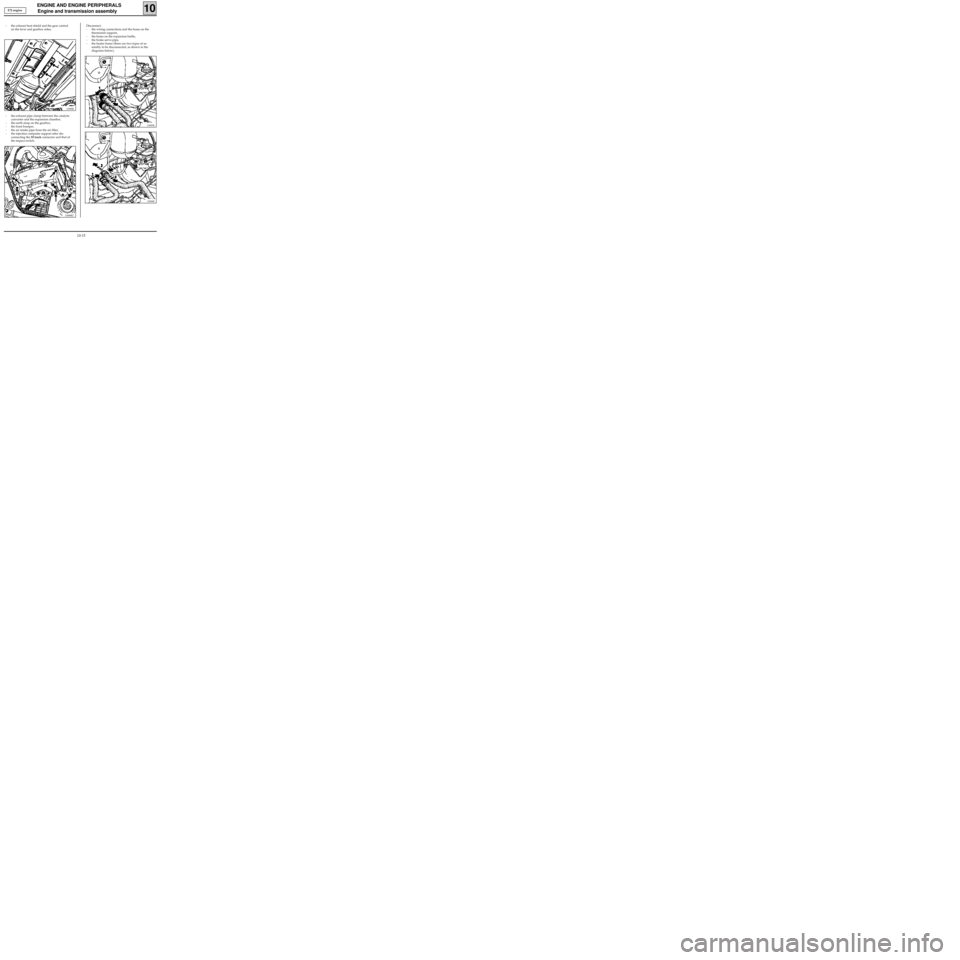
- the exhaust heat shield and the gear control
on the lever and gearbox sides,
12988R
- the exhaust pipe clamp between the catalytic
converter and the expansion chamber,
- the earth strap on the gearbox,
- the front bumper,
- the air intake pipe from the air filter,
- the injection computer support after dis-
connecting the 55 track connector and that of
the impact switch.
13088R2
Disconnect:
- the wiring connections and the hoses on the
thermostat support,
- the hoses on the expansion bottle,
- the brake servo pipe,
- the heater hoses (there are two types of as-
sembly to be disconnected, as shown in the
diagrams below),
13084R
E7J engine
10-15
Page 24 of 208

ENGINE AND ENGINE PERIPHERALS
Engine and transmission assembly
10
12988R
- the exhaust heat shield and the gear control
on the lever and gearbox sides,
- the exhaust downpipe,
- the earth strap on the gearbox,
- the front bumper,
- the air intake pipe of the air filter,
- the fuel supply and return unions (A) and (B),
- the connectors (2), (3), (4) and (5).
Unclip the fuel pipes from the air filter unit and
the timing cover and unclip the diesel filter from
its support and move the assembly to one side.
13083-1R
F8Q engine
10-20
Page 46 of 208
12mm torx socket
Angular tightening wrench
TOP AND FRONT OF ENGINE
Cylinder head gasket
11
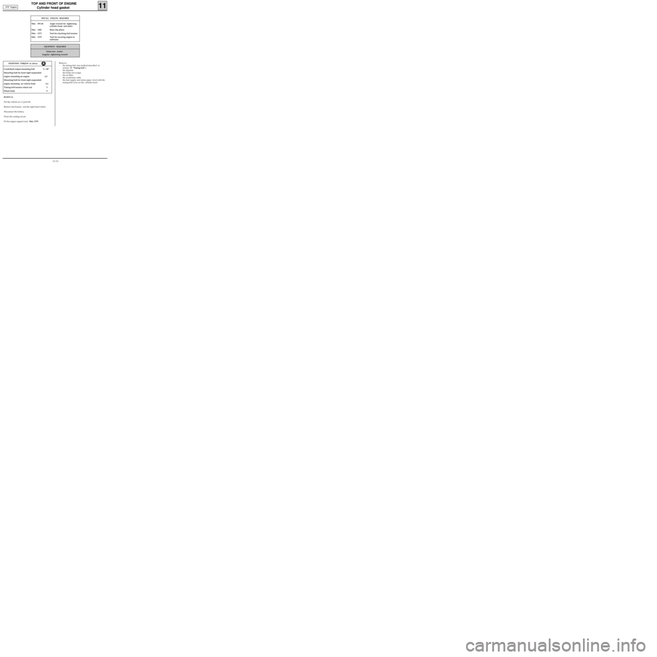
SPECIAL TOOLING REQUIRED
Mot. 591-04 Angle wrench for tightening
cylinder head and index
Mot. 1202 Hose clip pliers
Mot. 1273 Tool for checking belt tension
Mot. 1379 Tool for securing engine to
subframe
EQUIPMENT REQUIRED
TIGHTENING TORQUES (in daN.m)
Crankshaft output mounting bolt 2 + 90°
Mounting bolt for front right suspended
engine mounting on engine 6.2
Mounting bolt for front right suspended
engine mounting on vehicle body 6.2
Timing belt tension wheel nut 5
Wheel bolts 9
REMOVAL
Put the vehicle on a 2 post lift.
Remove the bonnet, and the right hand wheel .
Disconnect the battery.
Drain the cooling circuit.
Fit the engine support tool, Mot. 1379.Remove:
- the timing belt (see method described in
section 11 "Timing belt"),
- the dipstick,
- the brake servo pipe,
- the air filter,
- the accelerator cable,
- the fuel supply and return pipes level with the
timing belt cover on the cylinder head
D7F Engine
11-11
Page 53 of 208
TOP AND FRONT OF ENGINE
Cylinder head gasket
11
13339S
- the cover on the air filter assembly,
- the air filter assembly,
13338S
99310R
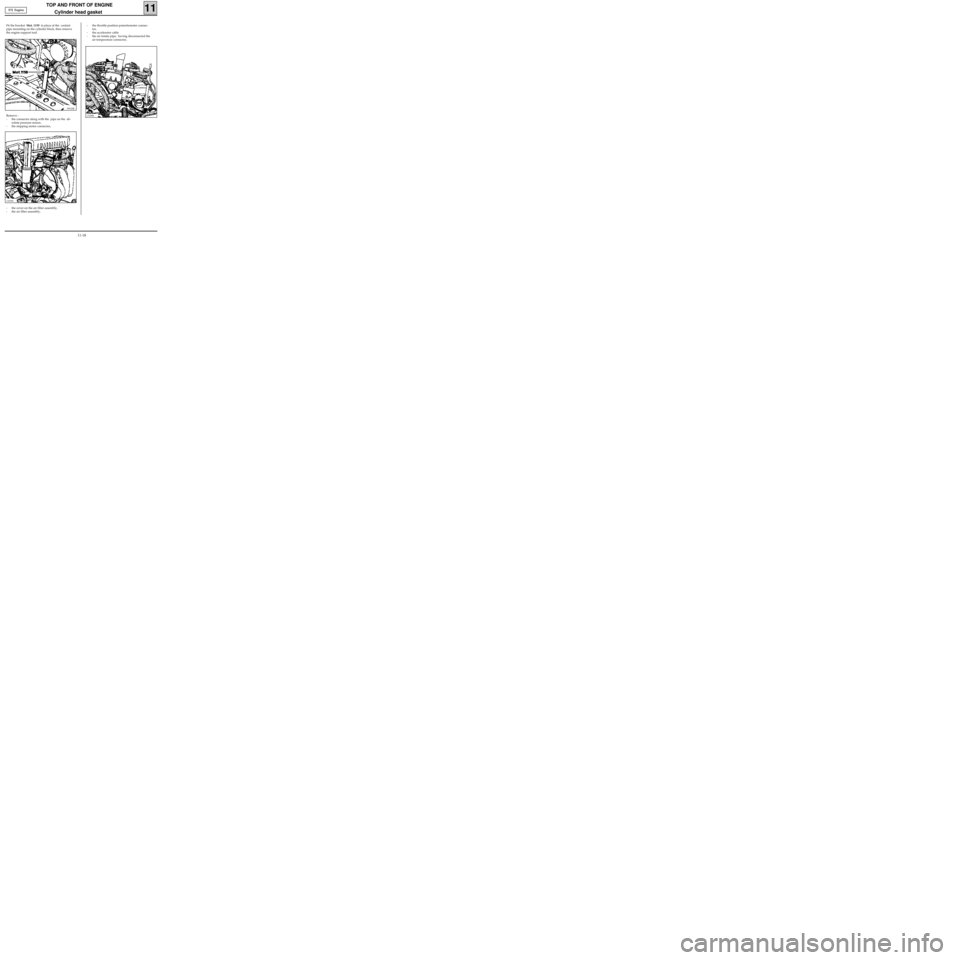
Remove :
- the connector along with the pipe on the ab-
solute pressure sensor,
- the stepping motor connector, Fit the bracket Mot. 1159 in place of the coolant
pipe mounting on the cylinder block, then remove
the engine support tool.- the throttle position potentiometer connec-
tor,
- the accelerator cable
- the air intake pipe, having disconnected the
air temperature connector, E7J Engine
11-18
Page 59 of 208
TOP AND FRONT OF ENGINE
Cylinder head gasket
11
Remove :
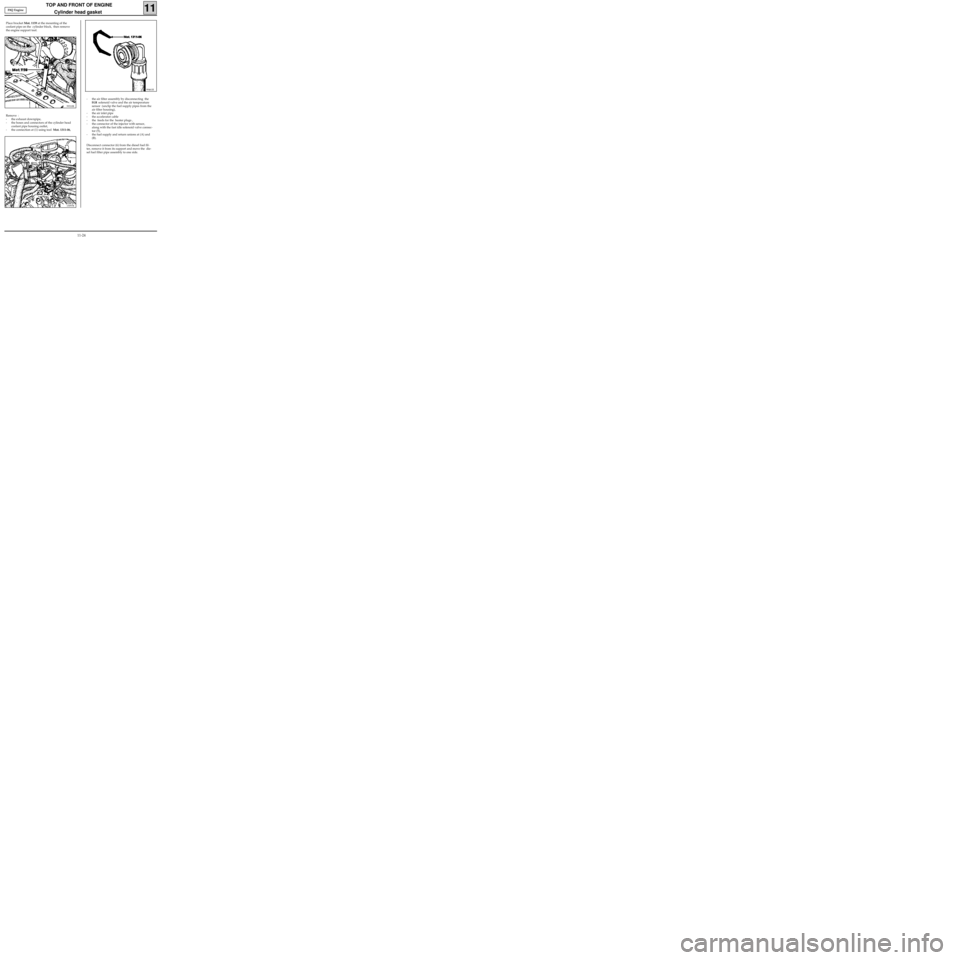
- the exhaust downpipe,
- the hoses and connectors of the cylinder head
coolant pipe housing outlet,
- the connection at (1) using tool Mot. 1311-06,
13097R
99461R
- the air filter assembly by disconnecting the
EGR solenoid valve and the air temperature
sensor (unclip the fuel supply pipes from the
air filter housing),
- the air inlet pipe
- the accelerator cable
- the feeds for the heater plugs ,
- the connector of the injector with sensor,
along with the fast idle solenoid valve connec-
tor (5),
- the fuel supply and return unions at (A) and
(B).
Disconnect connector (6) from the diesel fuel fil-
ter, remove it from its support and move the die-
sel fuel filter pipe assembly to one side. Place bracket Mot. 1159 at the mounting of the
coolant pipe on the cylinder block, then remove
the engine support tool.
99310R
F8Q Engine
11-24
Page 64 of 208
TOP AND FRONT OF ENGINE
Replacement of valve adjusters
11
SPECIAL TOOLING REQUIRED
Mot. 1366-01 Tool for removing valve adjusters
(additional item to Mot. 1366)
TIGHTENING TORQUES (in daN.m)
Studs for mounting manifolds on
cylinder head 1
Nut for mounting manifolds on
cylinder head 2.7
Mounting bolt for strut on inlet manifold 2.5
Mounting bolt for strut on cylinder block 2.5
Place the vehicle on a two-post lift
Disconnect the battery.
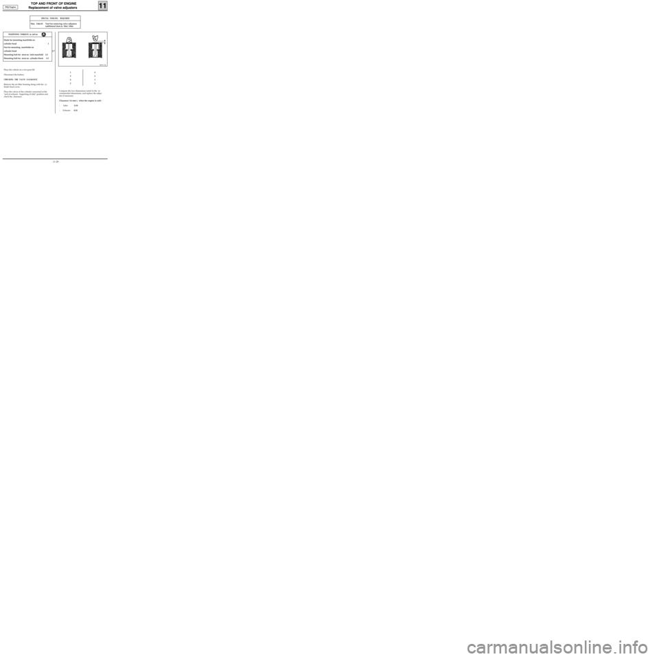
CHECKING THE VALVE CLEARANCE
Remove the air filter housing along with the cy-
linder head cover.
Place the valves of the cylinder concerned at the
"end of exhaust - beginning of inlet" position and
check the clearance .
86911-1S
1
3
4
24
2
1
3
Compare the two dimensions noted to the re-
commended dimensions, and replace the adjus-
ters if necessary .
Clearance ( in mm ), when the engine is cold :
- Inlet: 0.10
- Exhaust :0.25 F8Q Engine
11-29
Page 67 of 208
FUEL MIXTURE
Specifications
12
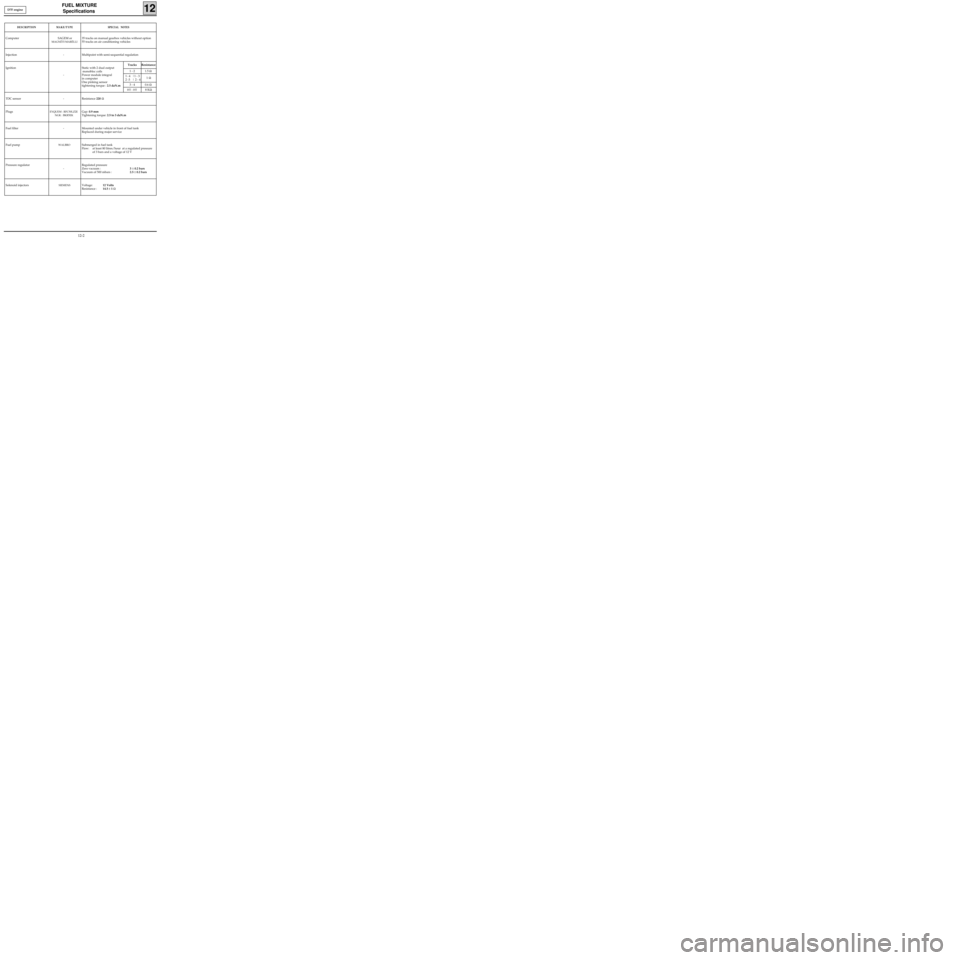
DESCRIPTIONMAKE/TYPESPECIAL NOTES
Computer SAGEM or
MAGNÉTI MARÉLLI
35 tracks on manual gearbox vehicles without option
55 tracks on air conditioning vehicles
Injection - Multipoint with semi-sequential regulation
Ignition
-Static with 2 dual output
monobloc coils
Power module integral
in computer
One pinking sensor
tightening torque : 2.5 daN.m
TDC sensor - Resistance 220 Ω
Plugs
EYQUEM : RFC50LZ2E
NGK : BKR5EKGap: 0.9 mm
Tightening torque: 2.5 to 3 daN.m
Fuel filter - Mounted under vehicle in front of fuel tank
Replaced during major service
Fuel pump
WALBROSubmerged in fuel tank
Flow: at least 80 litres/hour at a regulated pressure
of 3 bars and a voltage of 12 V
Pressure regulator
-Regulated pressure
Zero vacuum :3 ± 0.2 bars
Vacuum of 500 mbars :2.5 ± 0.2 bars
Solenoid injectors
SIEMENSVoltage:12 Volts
Resistance :14.5 ± 1 Ω
Tracks Resistance
1 - 2 1.5 Ω
1
- 4 |1 - 3
2 -3 | 2 - 41 Ω
3 - 4 0.6 Ω
HT - HT8 KΩ
D7F engine
12-2
Page 73 of 208
FUEL MIXTURE
Throttle body
12
Throttle body mounting bolt 1
TIGHTENING TORQUES (in daN.m)
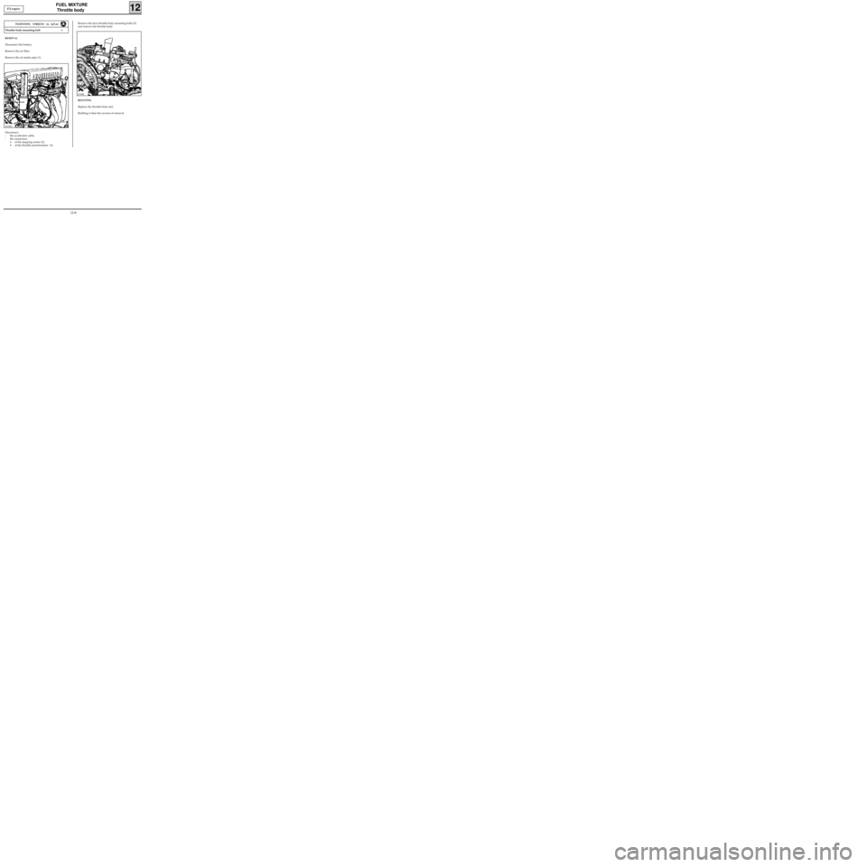
REMOVAL
Disconnect the battery.
Remove the air filter.
Remove the air intake pipe (1).
Disconnect:
- the accelerator cable,
- the connectors :
• of the stepping motor (2),
• of the throttle potentiometer (3).
E7J engine
Remove the four throttle body mounting bolts (5)
and remove the throttle body.
REFITTING
Replace the throttle body seal.
Refitting is then the reverse of removal.
13339R113338R
12-8
Page 75 of 208
FUEL MIXTURE
Inlet manifold
12
Inlet manifold bolt and nut 2
TIGHTENING TORQUES (in daN.m)
REMOVAL
Remove:
- the air filter,
- the injector gallery (see section 13).
Lift the vehicle.
Remove the strut (1) (to gain access to the bolt
fixing the strut on the right-hand side of the vehi-
cle, remove the mudguard and the right-hand
wheel).
E7J engine
13339R2
Disconnect the accelerator cable and the electrical
connectors (2) connected to the throttle body.
Remove the bolts and nuts (3) securing the mani-
fold. Lower the vehicle.
Remove the air intake pipe (A) connecting the
throttle body to the air filter.
13335-1R
13130R
12-10