warning RENAULT KANGOO 1997 KC / 1.G Foult Finding - Injection Service Manual
[x] Cancel search | Manufacturer: RENAULT, Model Year: 1997, Model line: KANGOO, Model: RENAULT KANGOO 1997 KC / 1.GPages: 363
Page 333 of 363
v0406.0
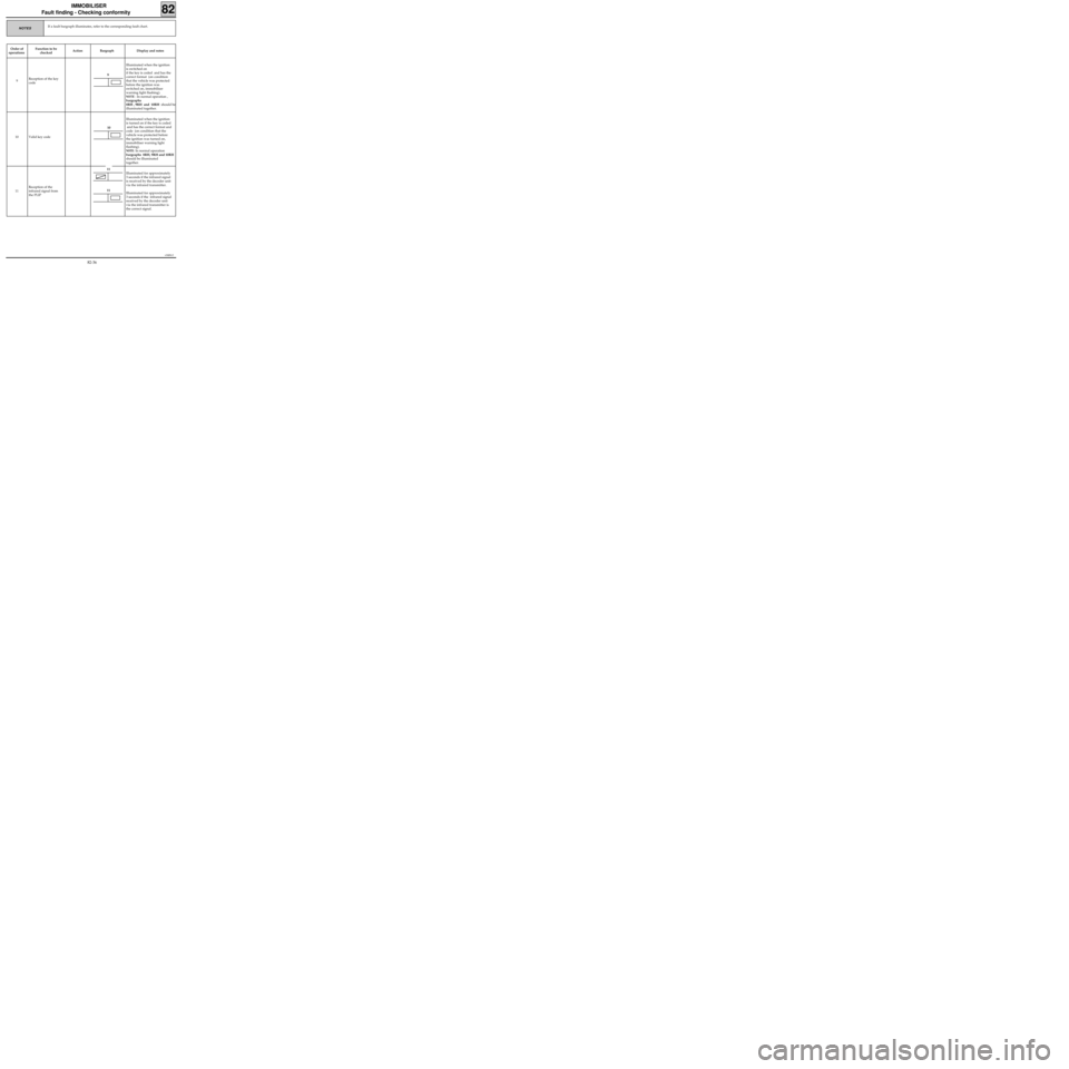
IMMOBILISER
Fault finding - Checking conformity
82
If a fault bargraph illuminates, refer to the corresponding fault chart.NOTES
Order of
operationsFunction to be
checkedAction Bargraph Display and notes
9Reception of the key
codeIlluminated when the ignition
is switched on
if the key is coded and has the
correct format (on condition
that the vehicle was protected
before the ignition was
switched on, immobiliser
warning light flashing).
NOTE : In normal operation ,
bargraphs
8RH , 9RH and 10RH should be
illuminated together.
10 Valid key code Illuminated when the ignition
is turned on if the key is coded
and has the correct format and
code (on condition that the
vehicle was protected before
the ignition was turned on,
immobiliser warning light
flashing).
NOTE: In normal operation
bargraphs 8RH, 9RH and 10RH
should be illuminated
together.
11Reception of the
infrared signal from
the PLIP Illuminated for approximately
3 seconds if the infrared signal
is received by the decoder unit
via the infrared transmitter.
Illuminated for approximately
3 seconds if the infrared signal
received by the decoder unit
via the infrared transmitter is
the correct signal.
9
10
11
11
82-36
Page 336 of 363
v0406.0
IMMOBILISER
Fault finding - Aid
82
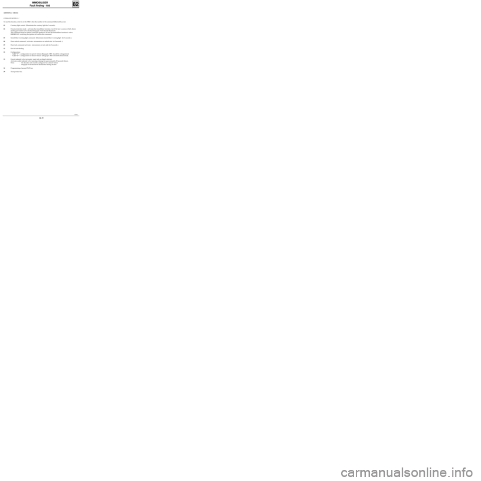
ADDITIONAL CHECKS
COMMAND MODES G--*
To use this function, enter G on the XR25 , then the number of the command followed by a star.
03Courtesy light control (Illuminates the courtesy light for 3 seconds).
04Forced protection mode : activates the immobiliser function even if the key is correct, which allows
starting prevention to be checked. Bargraph 9 left should illuminate.
This command must be entered when the ignition is off and the immobiliser function is active.
IMPORTANT: switching the ignition off cancels this command.
05Immobiliser warning light command (illuminates immobiliser warning light for 3 seconds ).
08Door unlock command (activates micromotors on unlock side for 3 seconds ).
09Door lock command (activates micromotors on lock side for 3 seconds ) .
13End of fault finding.
22Configuration :
-G 22 * 1 * = configuration for petrol vehicles (Bargraph 3RH should be extinguished).
-G 22 * 2 * = configuration for diesel vehicles (Bargraph 3RH should be illuminated).
23Forced solenoid valve test mode (used only on diesel vehicles).
Activates coded solenoid valve (opening/closing) for approximately 30 seconds (listen).
Note: - the decoder unit must be configured for a diesel vehicle
- Bargraph 8 left should be illuminated during the test.
32Programming of second PLIP key.
39Transponder line.
82-39
Page 340 of 363
1EC761.0
AIRBAG - SEAT BELT PRETENSIONERS
Fault finding -Introduction
CONDITIONS FOR THE APPLICATION OF THE CHECKS DEFINED IN THIS FAULT FINDING
The checks defined in this fault finding should only be applied to a vehicle when the fault bargraph is
illuminated, indicating that the fault is present on the vehicle at the time of checking. Only a computer
fault will require replacement of the computer, whether the bargraph is permanently illuminated or
flashing .
If the fault is not present but simply memorised, the bargraph flashes and application of the checks
recommended in the fault finding section will not allow the origin of the fault to be found. In this case,
only a check of the wiring and the connection of the component in question must be carried out (it is
possible to test the wiring concerned in fault finding mode to try to obtain permanent illumination of the
bargraph ).
TOOLING REQUIRED FOR OPERATIONS ON THE AIRBAG AND SEAT BELT PRETENSIONER SYSTEMS :
- XR25 (with minimum XR25 cassette N° 16).
- XRBAG the updated N° 3 version (with the new measuring lead and its adaptors as well as the 30 track
adaptor for operations on the computer connector).
REMINDER:
When carrying out an operation on the airbag/seat belt pretensioner systems , it is essential to lock the
computer with the XR25 command G80* to avoid all risk of triggering at the wrong time (all firing lines
will be inhibited). This operating mode will be indicated by illumination of the warning light on the
instrument panel.
Never carry out any measuring operations on the airbag and pretensioners trigger lines with equipment
other than the XRBAG.
Before using a dummy ignition module, ensure that its resistance is between 1.8 and 2.5 ohms.
Only 30 track connector computers with airbag(s) function are able to be tested with the XR25.
Computers with the pretensioner function only must be checked with the XRBAG by following the checks
described in the fault finding section.
The ignition must be switched off, then on again to make the warning light extinguish following erasure
of the memory using the command G0**.
88
88-1
Page 342 of 363
1EC761.0
AIRBAG - SEAT BELT PRETENSIONERS
Fault finding -Wiring
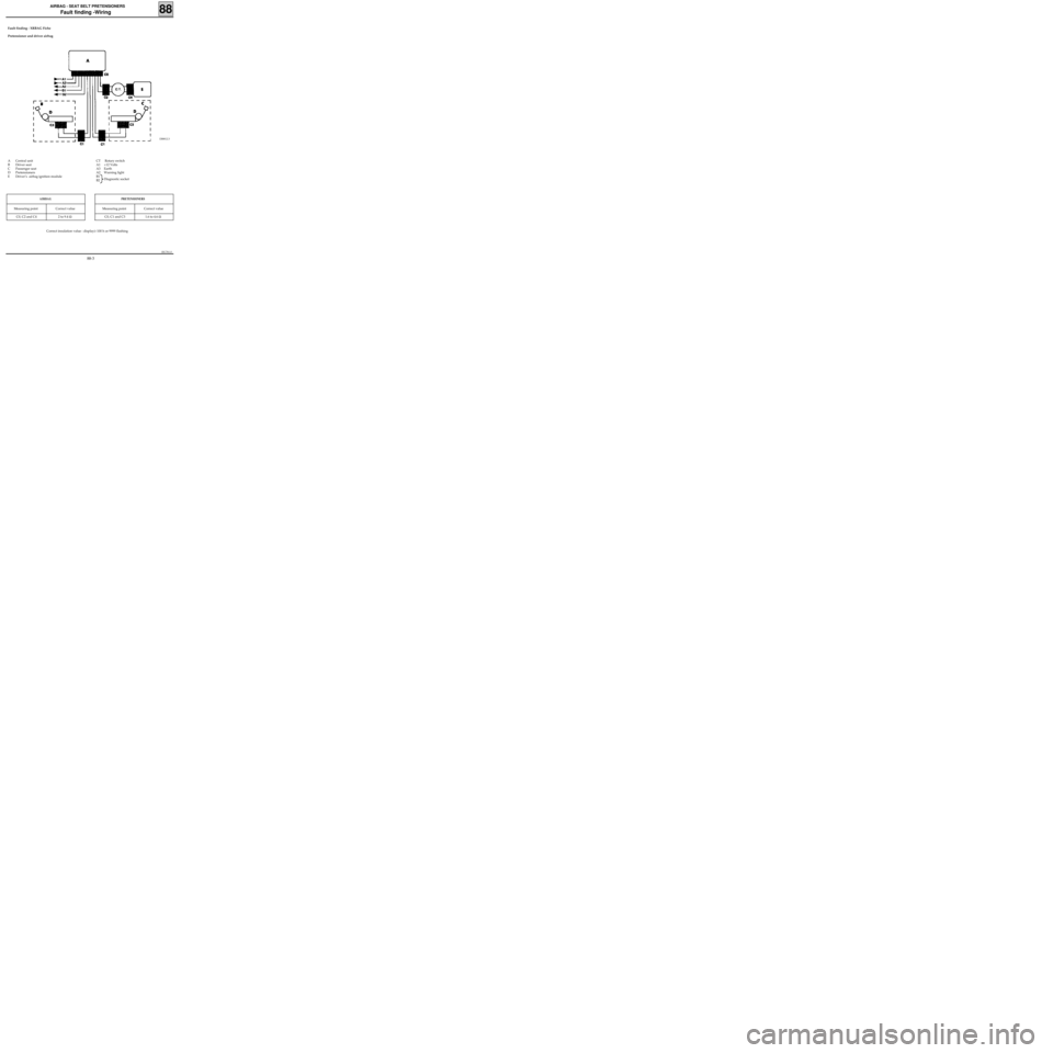
Fault finding - XRBAG Fiche
Pretensioner and driver airbag
88
DI8812.3
Correct insulation value : display≥ 100 h or 9999 flashing
PRETENSIONERS
Measuring point Correct value
C0, C1 and C3 1.6 to 4.6 Ω
AIRBAG
Measuring point Correct value
C0, C2 and C4 2 to 9.4 Ω
CT Rotary switch
A1 +12 Volts
A3 Earth
A2 Warning light
B1
B2Diagnostic socket A Central unit
B Driver seat
C Passenger seat
D Pretensioners
E Driver’s airbag ignition module
88-3
Page 343 of 363
1EC761.0
AIRBAG - SEAT BELT PRETENSIONERS
Fault finding -Wiring
Fault finding - XRBAG Fiche
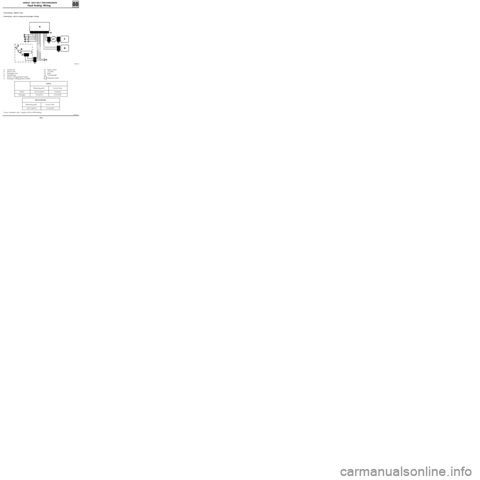
Pretensioner , driver’s airbag and passenger’s airbag
88
DI8813.2
PRETENSIONERS
Measuring point Correct value
C0, C1 and C3 1.6 to 4.6 Ω
AIRBAG
Measuring point Correct value
Driver C0, C2 and C4 2 to 9.4 Ω
Passenger C0 and C4 1.6 to 4.6 Ω
CT Rotary switch
A1 +12 Volts
A3 Earth
A2 Warning light
B1
B2Diagnostic socket A Central unit
B Driver’s seat
C Passenger’s seat
D Pretensioners
E Driver’s airbag ignition module
G Passenger’s airbag ignition module
Correct insulation value : display≥ 100 h or 9999 flashing
88-4
Page 356 of 363
1EC761.0
AIRBAG - SEAT BELT PRETENSIONERS
Fault finding - Interpretation of XR25 bargraphs
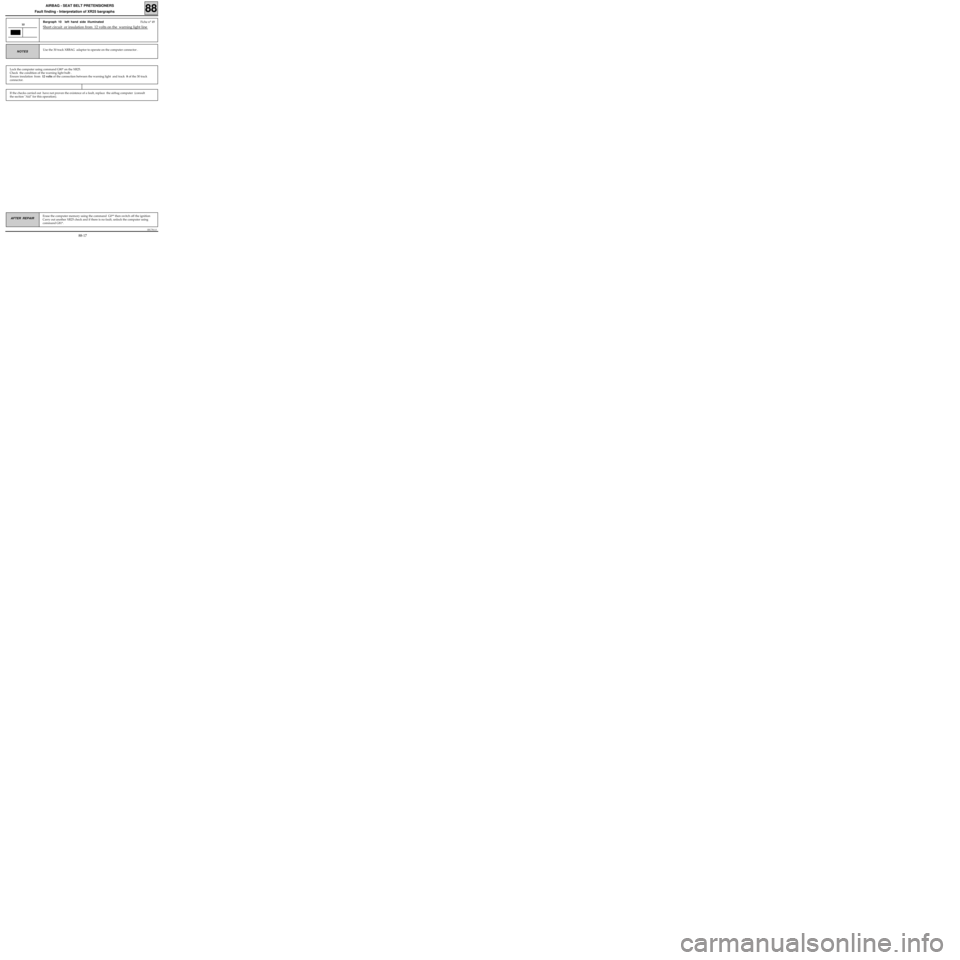
Bargraph 10 left hand side illuminated Fiche n° 49
Short circuit or insulation from 12 volts on the warning light line 10
Use the 30 track XRBAG adaptor to operate on the computer connector .NOTES
If the checks carried out have not proven the existence of a fault, replace the airbag computer (consult
the section "Aid" for this operation).
Lock the computer using command G80* on the XR25.
Check the condition of the warning light bulb .
Ensure insulation
from 12 volts of the connection between the warning light and track 8 of the 30 track
connector.
Erase the computer memory using the command G0** then switch off the ignition
Carry out another XR25 check and if there is no fault, unlock the computer using
command G81*.AFTER REPAIR
88
88-17
Page 357 of 363
1EC761.0
AIRBAG - SEAT BELT PRETENSIONERS
Fault finding - Interpretation of XR25 bargraphs
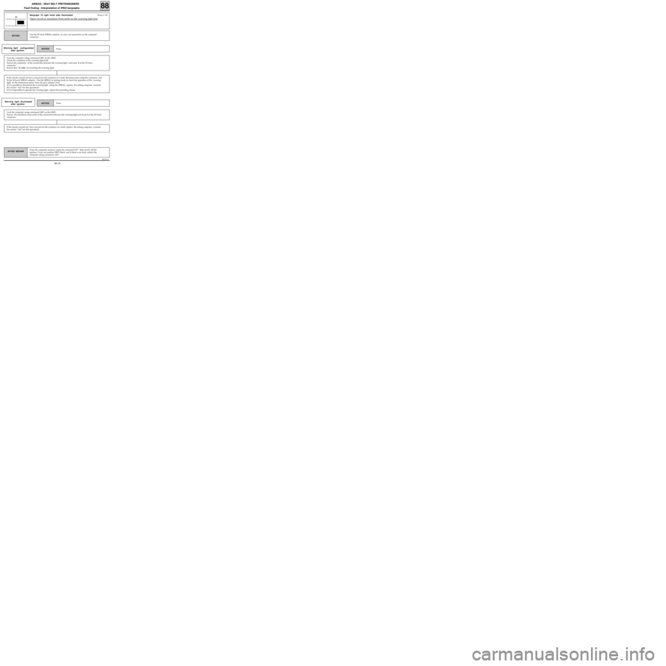
Bargraph 10 right hand side illuminated Fiche n° 49
Open circuit or insulation from earth on the warning light line10
Use the 30 track XRBAG adaptor to carry out operations on the computer
connector .NOTES
Warning light extinguished
after ignition
Lock the computer using command G80* on the XR25.
Check the condition of the warning light bulb.
Ensure the continuity of the connection between the warning light and track 8 of the 30 track
connector.
Ensure that 12 volts are reaching the warning light .
If the checks carried out have not proven the existence of a fault, disconnect the computer connector and
fit the 30 track XRBAG adaptor . Use the XRBAG in testing mode to check the operation of the warning
light on the instrument panel from the grey adaptor wire.
If it is possible to illuminate the warning light using the XRBAG, replace the airbag computer (consult
the section "Aid" for this operation).
If it is impossible to operate the warning light , repeat the preceding checks.
NoneNOTES Warning light illuminated
after ignition
Lock the computer using command G80* on the XR25.
Ensure the insulation from earth of the connection between the warning light and track 8 of the 30 track
connector .
If the checks carried out have not proven the existence of a fault, replace the airbag computer (consult
the section "Aid" for this operation).
None
Erase the computer memory using the command G0** then switch off the
ignition. Carry out another XR25 check and if there is no fault, unlock the
computer using command G81*.AFTER REPAIR
88
NOTES
88-18
Page 359 of 363
1EC761.0
AIRBAG - SEAT BELT PRETENSIONERS
Fault finding - Interpretation of XR25 bargraphs
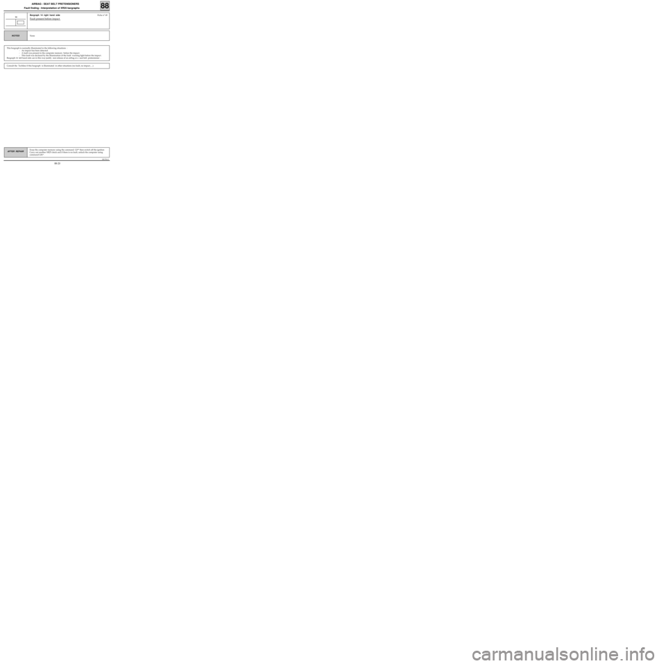
Bargraph 14 right hand side Fiche n° 49
Fault present before impact 14
NoneNOTES
This bargraph is normally illuminated in the following situations :
- An impact has been detected.
- A fault was present in the computer memory before the impact.
- This fault was declared by the illumination of the fault warning light before the impact .
Bargraph 14 left hand side can in this way justify non-release of an airbag or a seat belt pretensioner .
Consult the Techline if this bargraph is illuminated in other situations (no fault, no impact, ...).
Erase the computer memory using the command G0** then switch off the ignition
Carry out another XR25 check and if there is no fault, unlock the computer using
command G81*.AFTER REPAIR
88
88-20
Page 361 of 363
1EC761.0
AIRBAG - SEAT BELT PRETENSIONERS
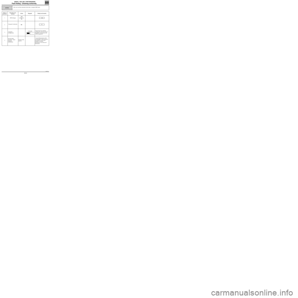
Fault finding - Checking conformity
Only carry out this conformity check after a complete XR25 check.NOTES
Order of
operationsOperation to be
checked Action Bargraph Display and remarks
1 XR25 dialogueD49
(selector on
S8)
I.Ab
2 Computer Conformity
#022 2
3 Computer
Configuration Ensure that the computer
configuration shown by these 3
bargraphs corresponds to the
vehicle equipment.
4Warning light
operation - check
computer
initialisation Switch on the
ignition 3 second illumination of the
warning light when turning on
the ignition (consult fault
finding if it remains
illuminated or if it does not
illuminate).
17 / 18 / 19
88
88-22
Page 363 of 363
1EC761.0
AIRBAG - SEAT BELT PRETENSIONERS
Fault finding - Aid
REPLACING THE AIRBAG COMPUTER
The airbag computers are sold in locked mode to avoid all risk of release at the wrong time (all
trigger lines are inhibited). This operational mode is indicated by the illumination of the warning
light on the instrument panel.
When replacing the airbag computer, follow this procedure :
- Ensure that the ignition is switched off.
- Replace the computer.
- Carry out an XR25 check.
- Unlock the computer using command G81*, only when no fault is declared.
88
88-24