warning RENAULT KANGOO 1997 KC / 1.G Foult Finding - Injection Owner's Manual
[x] Cancel search | Manufacturer: RENAULT, Model Year: 1997, Model line: KANGOO, Model: RENAULT KANGOO 1997 KC / 1.GPages: 363
Page 283 of 363
B76531.0
ELECTRONICALLY CONTROLLED HYDRAULIC SYSTEM
Fault finding - Fault chart 38
ABS BOSCH
5.3
AFTER REPAIR Carry out a road test, then a check with the XR25 kit.
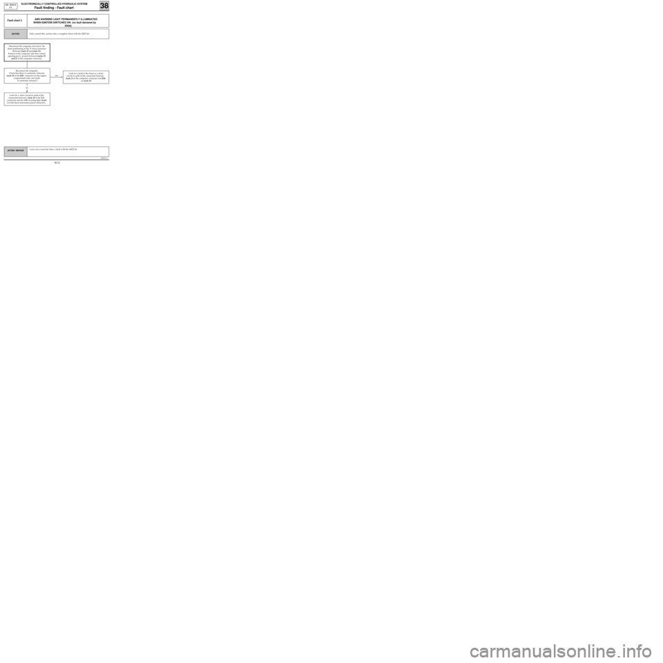
ABS WARNING LIGHT PERMANENTLY ILLUMINATED
WHEN IGNITION SWITCHED ON (no fault declared by
XR25)Fault chart 2
Only consult this section after a complete check with the XR25 kit.NOTES
yes
Look for a short circuit to earth of the
connection between track 10 of the R36
connector and the ABS warning light (track
3 of the black instrument panel connector).Look for a fault in the shunt or a short
circuit to earth of the connection between
track 21 of the computer connector and R36
on track 10.
no
Disconnect the computer and check the
shunt positioning in the 31 track connector
(between track 19 and track 21).
Ensure on the computer side that a shunt
opening pin is present between tracks 19
and 21 of the computer connector.
Reconnect the computer.
Check that there is continuity between
track 10 of the R36 connector on the engine
compartment side, and earth.
Is continuity ensured ?
38-22
Page 284 of 363
B76531.0
ELECTRONICALLY CONTROLLED HYDRAULIC SYSTEM
Fault finding - Fault chart 38
ABS BOSCH
5.3
AFTER REPAIR Carry out a road test, then a check with the XR25 kit.
REILLUMINATION OF WARNING LIGHT AFTER STARTING THE ENGINE
TEMPORARY ILLUMINATION OF ABS WARNING LIGHT WHEN DRIVINGFault chart 3
Check the voltage of the computer power supply : 9.5 volts < correct voltage < 17.5 volts.
If necessary, carry out the following operations :
- Check the battery charge (check the charging circuit if necessary).
- Check the tightness and condition of the battery terminals.
- Check the ABS earths (tightness of two earth bolts above the ABS assembly).
Disconnect the computer and check the condition and the positioning of the shunt in the 31 track
connector (between track 19 and track 21).
Check on the computer side, the condition of the shunt opening pin.
Only consult this section after a complete check with the XR25 kit.NOTES
38-23
Page 295 of 363
B76531.0
ELECTRONICALLY CONTROLLED HYDRAULIC SYSTEM
Fault finding - Fault chart 38
ABS BOSCH
5.3
AFTER REPAIR Carry out a road test, then a check with the XR25 kit.
ABS WARNING LIGHT DOES NOT ILLUMINATE,
COMPUTER DISCONNECTEDFault chart 14
Disconnect the ABS computer .
Check if the shunt is present between track 19 and track 21 of the computer connector.
Only consult this section after a complete check with the XR25 kit.NOTES
38-34
Page 302 of 363
v0406.0
IMMOBILISER
Fault finding- Interpretation of XR25 Bargraphs 82
Erase the memorised fault by entering G0** on the XR25 keyboard.
Carry out a conformity check.
Check that the immobiliser system is operating.AFTER REPAIR
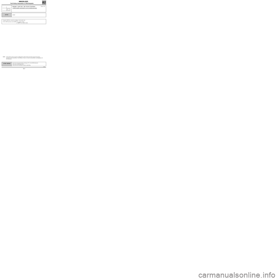
Bargraph 3 right hand side incorrect illumination
CODED DIESEL SOLENOID VALVE CONFIGURATION
3
NONENOTES
Fiche n° 56
Using the XR25 kit, correctly reconfigure the decoder unit.
On the XR25 keyboard, enter G22*1* for a petrol vehicle
or G22*2* for a diesel vehicle
NOTE: In the diesel version, incorrect configuration of the decoder unit does not prevent proper
operation of the immobiliser. Nevertheless, if there is a fault, the immobiliser warning light will
not illuminate.
82-5
Page 305 of 363
v0406.0
IMMOBILISER
Fault finding- Interpretation of XR25 Bargraphs 82
Erase the memorised fault by entering GO** on the XR25 keyboard.
Carry out a conformity check.
Check operation of the immobiliser system.AFTER REPAIR
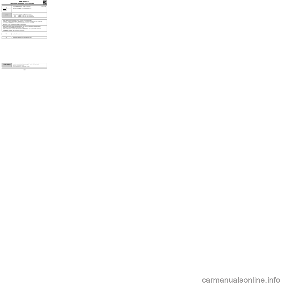
Bargraph 6 left hand side illuminated
DIESEL SOLENOID VALVE CLEARANCE
6
Check that the computer configuration is correct :
- diesel : Bargraph 3 right hand side illuminated
- petrol : Bargraph 3 right hand side extinguishedNOTES
Fiche n° 56
Set the XR25 to pulse sensor mode (button "G", input on terminal "Vin").
Ignition on, check for pulses on track A6 of the 18 track decoder unit connector (test with the decoder
unit and the coded electronic unit of the solenoid valve connectors connected).
Ignition on, if there are no pulses, change the decoder unit.
Switch on the ignition for 30 consecutive seconds, then switch off the ignition and wait until the
immobiliser warning light flashes (immobiliser active).
Switch on the ignition again and check that bargraph 8 left hand side is permanently illuminated.
Is Bargraph 8 left hand side permanently illuminated ?
Replace the decoder unit.YES
NOReplace the solenoid valve coded electronic unit.
82-8
Page 311 of 363

v0406.0
IMMOBILISER
Fault finding - Customer complaints (petrol version) 82
Only consult these customer complaints after a complete check using the XR25 NOTES
NO XR25/DECODER UNIT COMMUNICATION
IGNITION ON, THE IMMOBILISER WARNING LIGHT FLASHES PERMANENTLY
(impossible to start)
THE IMMOBILISER WARNING LIGHT REMAINS PERMANENTLY ILLUMINATED
(even with the ignition off) OR IS PERMANENTLY EXTINGUISHED
IGNITION ON, THE INJECTION WARNING LIGHT FLASHES PERMANENTLY
(impossible to start)
WHILE DRIVING (deceleration) AND AT IDLE SPEED, THE INJECTION
WARNING LIGHT FLASHES PERMANENTLY
THE VEHICLE WILL NOT START
Fault
Chart
1
Fault
Chart
2
Fault
Chart
3
Fault
Chart
4
Fault
Chart
5
Fault
Chart
6
82-14
Page 313 of 363
v0406.0
IMMOBILISER
Fault finding - Fault Chart (petrol version) 82
AFTER REPAIRCarry out a conformity check.
Check that the immobiliser system is working correctly.
Erase fault memory G0**.
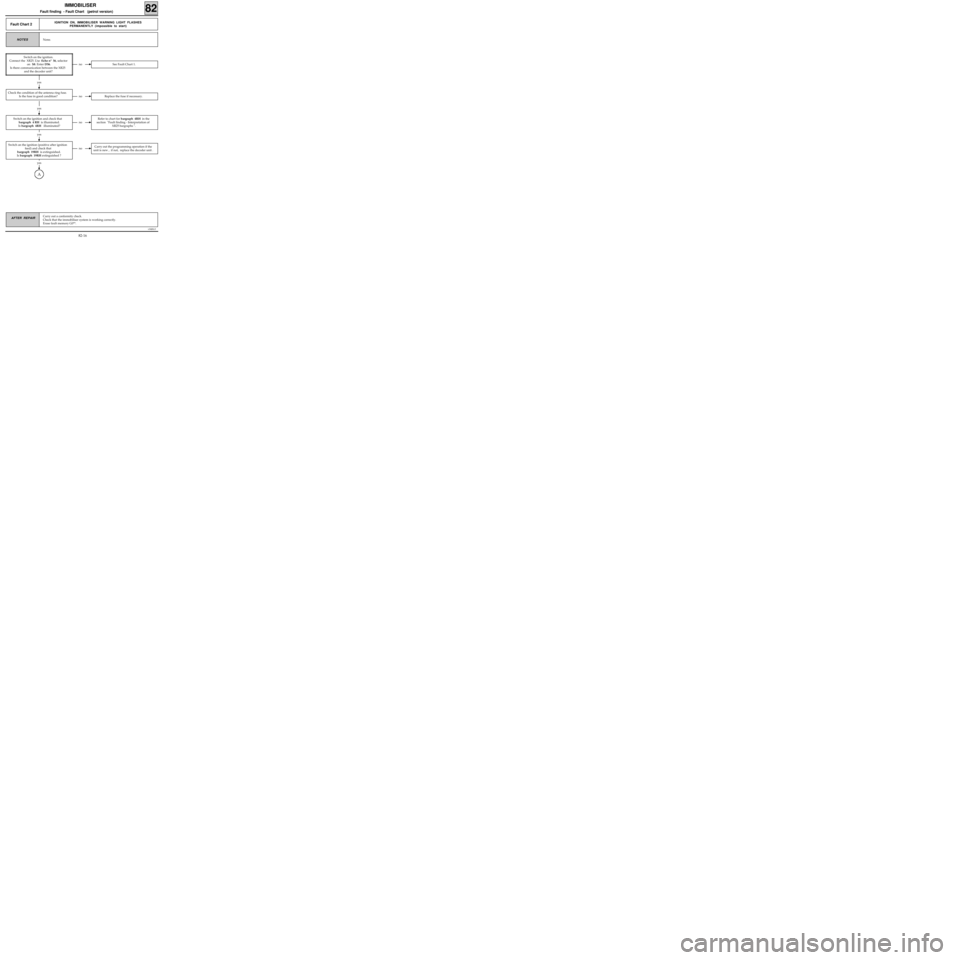
Fault Chart 2IGNITION ON, IMMOBILISER WARNING LIGHT FLASHES
PERMANENTLY (impossible to start)
None. NOTES
no See Fault Chart 1.
Switch on the ignition.
Connect the
XR25. Use fiche n° 56, selector
on S8. Enter D56.
Is there communication between the XR25
and the decoder unit?
yes
no Replace the fuse if necessary.
yes
Check the condition of the antenna ring fuse.
Is the fuse in good condition?
no
Refer to chart for bargraph 4RH in the
section "Fault finding - Interpretation of
XR25 bargraphs ".
yes
no Carry out the programming operation if the
unit is new , if not, replace the decoder unit .
Switch on the ignition and check that
bargraph 4 RH is illuminated.
Is bargraph 4RH illuminated?
yes
A
Switch on the ignition (positive after ignition
feed) and check that
bargraph 19RH is extinguished.
Is bargraph 19RH extinguished ?
82-16
Page 314 of 363
v0406.0
IMMOBILISER
Fault finding - Fault Chart (petrol version) 82
AFTER REPAIRCarry out a conformity check.
Check that the immobiliser system is working correctly.
Erase fault memory G0**.
Fault Chart 2
CONT 1
A
yes
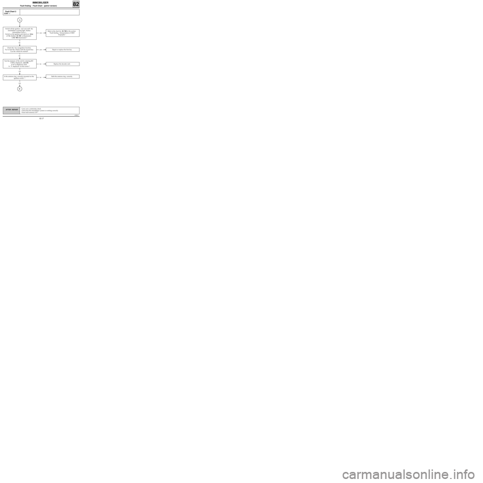
Refer to the chart for BG 7RH in the section
"Fault finding - Interpretation of XR25
bargraphs ".
no
Switch off the ignition and wait until the
immobiliser warning light flashes
(immobiliser active ).
Switch on the ignition and check on fiche
n° 56 whether
BG 7RH is illuminated .
Is
BG 7RH illuminated ?
yesRepair or replace the first key.
no
no Replace the decoder unit .
Check the key recognition function.
Try to start the vehicle with the second key.
Can the vehicle be started?
yes
B
yes
no Refit the antenna ring correctly.Is the antenna ring correctly mounted on the
ignition switch ?
Test the memory of the unit by entering #65
If "0" is displayed , test OK
If "1" is displayed ,fault .
Is "0" displayed on the screen ?
82-17
Page 315 of 363
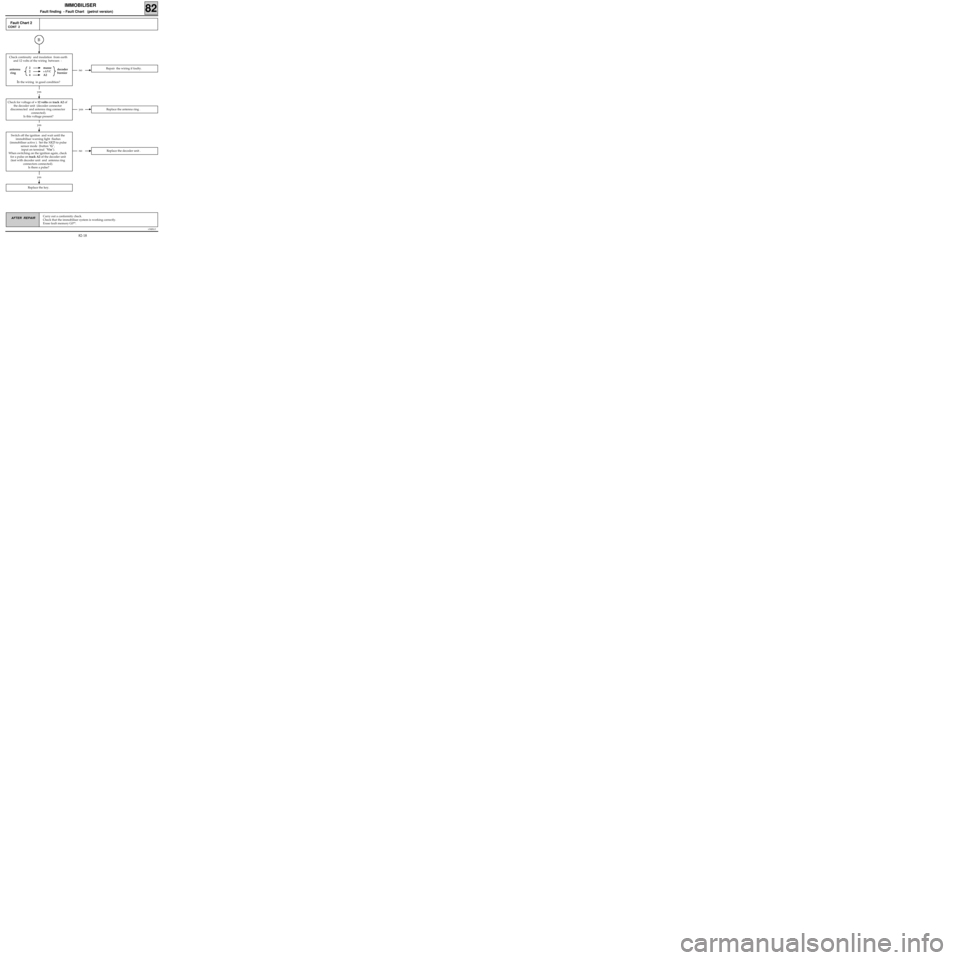
Check continuity and insulation from earth
and 12 volts of the wiring between :
2 masse
2
+AVC
4A2
Is the wiring in good condition?
v0406.0
IMMOBILISER
Fault finding - Fault Chart (petrol version) 82
AFTER REPAIRCarry out a conformity check.
Check that the immobiliser system is working correctly.
Erase fault memory G0**.
Fault Chart 2
CONT 2
B
no Repair the wiring if faulty.decoder
bornierantenna
ring
yes
yesReplace the antenna ring .
yes
no Replace the decoder unit .
Check for voltage of + 12 volts on track A2 of
the decoder unit (decoder connector
disconnected and antenna ring connector
connected).
Is this voltage present?
yes
Replace the key.
Switch off the ignition and wait until the
immobiliser warning light flashes
(immobiliser active ). Set the XR25 to pulse
sensor mode (button "G",
input on terminal "Vin").
When switching on the ignition again, check
for a pulse on track A2 of the decoder unit
(test with decoder unit and antenna ring
connectors connected).
Is there a pulse?
82-18
Page 316 of 363
v0406.0
IMMOBILISER
Fault finding - Fault Chart (petrol version) 82
AFTER REPAIRCarry out a conformity check.
Check that the immobiliser system is working correctly.
Erase fault memory G0**.
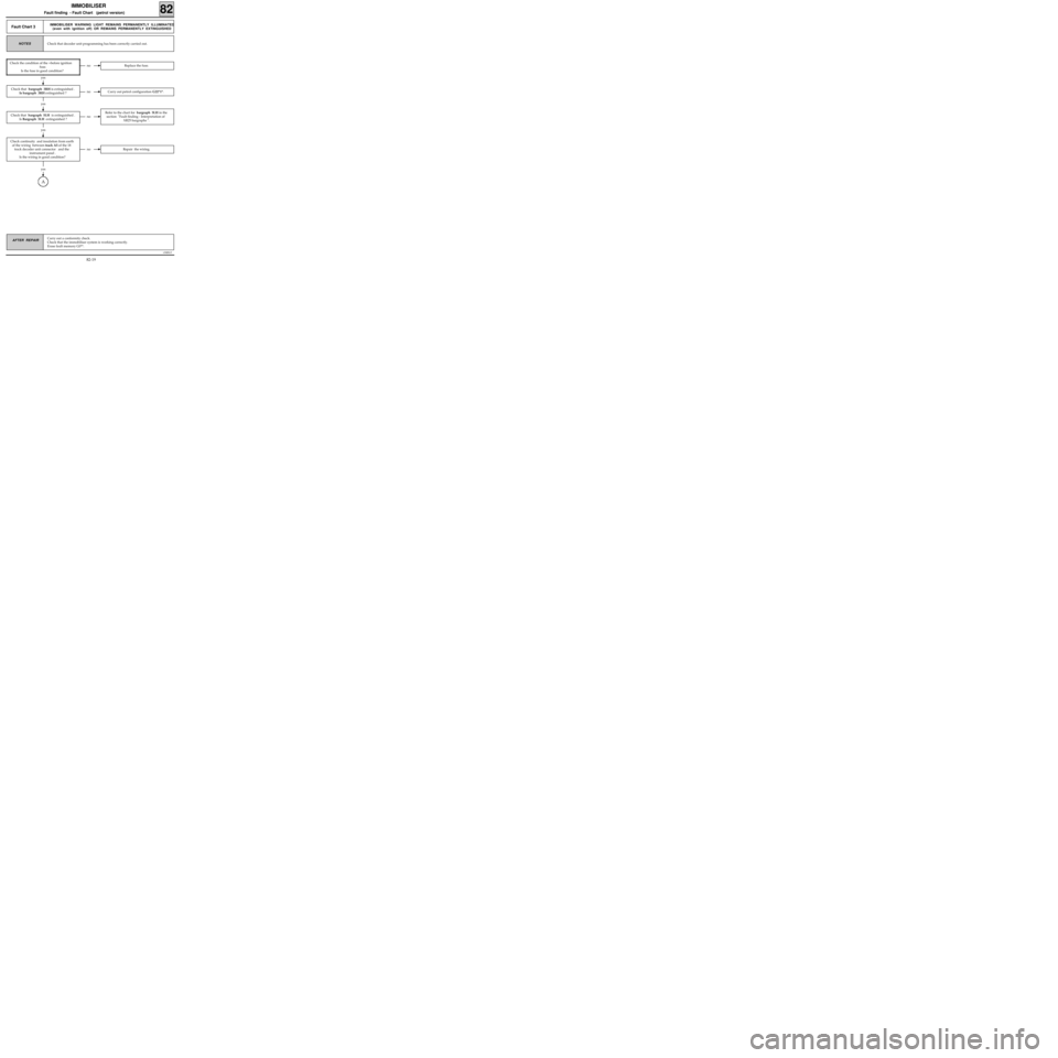
Fault Chart 3IMMOBILISER WARNING LIGHT REMAINS PERMANENTLY ILLUMINATED
(even with ignition off) OR REMAINS PERMANENTLY EXTINGUISHED
Check that decoder unit programming has been correctly carried out.NOTES
no Replace the fuse.
yes
Check the condition of the +before ignition
fuse.
Is the fuse in good condition?
no Carry out petrol configuration G22*1*.
yes
no
Refer to the chart for bargraph 5LH in the
section "Fault finding - Interpretation of
XR25 bargraphs ".
Check that bargraph 3RH is extinguished .
Is bargraph 3RH extinguished ?
yes
no Repair the wiring.
Check continuity and insulation from earth
of the wiring between track A5 of the 18
track decoder unit connector and the
instrument panel .
Is the wiring in good condition?
Check that bargraph 5LH is extinguished .
Is Bargraph 5LH extinguished ?
yes
A
82-19