sensor RENAULT KANGOO 1997 KC / 1.G Foult Finding - Injection Manual Online
[x] Cancel search | Manufacturer: RENAULT, Model Year: 1997, Model line: KANGOO, Model: RENAULT KANGOO 1997 KC / 1.GPages: 363
Page 259 of 363
JSA051.0
INJECTION
Fault finding - Checking conformity
17
D7F 710
engine -
55 tracks
Checks to be carried out during a road test.NOTES
Order of
operationsFunction to be
checkedAction Bargraph Display and notes
1 Change to status testG01*
10.NJ
Use fiche n° 27
status test side
2 No fault presentEnsure this bargraph is not
flashing, otherwise enter
G02* and turn over the fiche.
IMPORTANT: This bargraph
may flash if the vehicle has no
immobiliser. Ignore this
bargraph if fault bargraph 2 RH
side is illuminated and *22 = 2
dEF.
Repair the faulty component
the erase the memory (G0**)
and return to the status test
(G01*)
3 Canister bleed# 23Canister bleed is authorised
X = variable and > 0.7
4Vehicle speed
information# 18X = vehicle speed read on
speedometer
5 Pinking sensor Vehicle under
load and
engine speed
2000 rpm
# 13
# 15X = variable and not zero
0 ≤ X ≤ 6
(if there is a sensor fault, the
advance is retarded
systematically by 4° , which is
not visible using # 15)
11
20
17-216
Page 268 of 363
B76531.0
ELECTRONICALLY CONTROLLED HYDRAULIC SYSTEMS
Fault finding - Interpretation of XR25 bargraphs
38
ABS BOSCH
5.3
Erase computer memory(GO**).
Carry out a road test followed by a check with the XR25 kit.AFTER REPAIR
Bargraph 6 left hand side illuminated
Front left wheel sensor circuit
6
None.
NOTES
Fiche n° 53
If the resistance is correct, check and ensure the continuity of the connection between the sensor
connector and the computer connector:
- between one track of the sensor connector and track 7 of the computer connector,
- between the other track of the sensor connector and track 6 of the computer connector.
Also check the insulation between these connections.
Carry out a visual inspection of the sensor wiring and check the quality of the connection on the 31 track
computer connector.
If all the checks are correct, reconnect the computer and the wheel speed sensor then erase the computer
memory.
Exit fault finding mode(G13*) and switch off the ignition.
Switch the ignition on and replace the sensor if the fault reappears.
If the fault reappears after replacing the sensor, replace the computer.
Check the connection and condition of the sensor connections.
If the connector is correct, check the resistance of the sensor at its connector..
Replace the sensor if its resistance is not approximately 1.6 Kohms (1,6 Kohms ± 320 ohms).
38-7
Page 269 of 363
B76531.0
ELECTRONICALLY CONTROLLED HYDRAULIC SYSTEMS
Fault finding - Interpretation of XR25 bargraphs
38
ABS BOSCH
5.3
Erase computer memory(GO**).
Carry out a road test followed by a check with the XR25 kit.AFTER REPAIR
Bargraph 6 Right hand side illuminated
Front right wheel sensor circuit
6
None.
NOTES
Fiche n° 53
If the resistance is correct , check and ensure the continuity of the connections between the sensor
connector and the computer connector :
- between one track of the sensor connector and track 3 of the computer connector,
- between the other track of the sensor connector and track 5 of the computer connector.
Also check the insulation between these connections.
Carry out a visual inspection of the sensor wiring and check the quality of the connections on the 31
track computer connector.
If all the checks are correct, reconnect the computer and the wheel speed sensor, then erase the
computer memory.
Exit the fault finding mode(G13*) and switch off the ignition.
Switch the ignition on and replace the sensor if the fault reappears .
If the fault reappears after replacing the sensor, replace the computer.
Check the connection and condition of the sensor connections.
If the connector is correct, check the resistance of the sensor at its connector.
Replace the sensor if its resistance is not approximately 1.6 Kohms (1.6 Kohms ± 320 ohms).
38-8
Page 270 of 363
B76531.0
ELECTRONICALLY CONTROLLED HYDRAULIC SYSTEMS
Fault finding - Interpretation of XR25 bargraphs
38
ABS BOSCH
5.3
Erase computer memory(GO**).
Carry out a road test followed by a check with the XR25 kit.AFTER REPAIR
Bargraph 7 left hand side illuminated
Rear left wheel sensor circuit
7
None.
NOTES
Fiche n° 53
If all checks are correct, reconnect the computer and wheel speed sensor, then erase the computer
memory.
Exit fault finding mode(G13*) and switch off the ignition.
Switch on the ignition and replace the sensor if the fault reappears.
If the fault reappears after replacing the sensor, replace the computer.
Check the connection and condition of the sensor connections.
Check the connections at the intermediate connection under the body (R101).
If the connector is correct, check the resistance of the sensor at its connector. Replace the sensor if the
resistance is not approximately 1.6 Kohms (1.6 Kohms ± 320 ohms).
If the resistance is correct, check and ensure the continuity of the connections between the sensor
connector and the computer connector :
- between one track of the sensor connector and track 8 of the computer connector (via track B of the
connector under the body R101),
- between the other track of the sensor connector and track 9 of the computer connector (via track A of
the connector under the body R101).
Also check the insulation between these connections.
Carry out a visual inspection of the sensor wiring and check the quality of the connections on the 31 track
computer connector.
38-9
Page 271 of 363
B76531.0
ELECTRONICALLY CONTROLLED HYDRAULIC SYSTEMS
Fault finding - Interpretation of XR25 bargraphs
38
ABS BOSCH
5.3
Erase computer memory(GO**).
Carry out a road test followed by a check with the XR25 kit.AFTER REPAIR
Bargraph 7 Right hand side illuminated
Rear right wheel sensor circuit
7
None.
NOTES
Fiche n° 53
If all checks are correct, reconnect the computer and the wheel speed sensor, then erase the computer
memory.
Exit fault finding mode(G13*) and switch off the ignition.
Switch on the ignition and replace the sensor if the fault reappears.
If the fault reappears after replacing the sensor, replace the computer.
Check the connection and condition of the sensor connections.
Check the connections at the intermediate connector under the body (R101).
If the connector is correct , check the resistance of the sensor at its connector.
Replace the sensor if its resistance is not approximately 1.6 Kohms (1.6 Kohms ± 320 ohms).
If the resistance is correct, check and ensure the continuity of the connections between the sensor
connector and the computer connector :
- between one track of the sensor connector and track 1 of the computer connector (via track D of the
connector under the body R101),
-between the other track of the sensor connector and track 2 of the computer connector (via track C of
the connector under the body R101).
Also check the insulation between these connections.
Carry out a visual inspection of sensor wiring and check the quality of the connections on the 31 track
computer connector.
38-10
Page 272 of 363
B76531.0
ELECTRONICALLY CONTROLLED HYDRAULIC SYSTEMS
Fault finding - Interpretation of XR25 bargraphs
38
ABS BOSCH
5.3
Erase computer memory(GO**).
Carry out a road test followed by a check with the XR25 kit.AFTER REPAIR
Bargraph 8 right or left hand side flashing
Front right or front left wheel sensor signal
Even if they are present at time of testing, these faults will always be declared by
BG 8 flashing on the left or right hand side.
To confirm their presence and therefore the need to apply the fault finding be-
low, carry out a road test. The fault is present if the bargraph illuminates during
the test.
If bargraphs 6 and 8 left hand side are both illuminated, deal with bargraph 6
first.
If bargraphs 6 and 8 right hand side are both illuminated, deal with bargraph 6
first.
NOTES
Fiche n° 53 8
Check the quality of the wheel speed sensor mounting (its position and that it is tightened to
recommended torque).Check the sensor / target air gap over one wheel revolution : 0.13 mm < air
gap< 1.96 mm. Check conformity of the target (condition, number of
teeth=26)
Carry out a visual inspection of the sensor wiring and check the quality of the connections on the 31 track
computer connector.
If all checks are correct, reconnect the computer and the wheel speed sensor, then erase the computer
memory.
Leave fault finding mode(G13*) and carry out a road test. Replace the sensor if the fault reappears.
If the fault reappears after replacing the sensor, it may be caused by an operating fault on a solenoid
valve and it is therefore necessary to carry out the hydraulic check of the solenoid valves with the XR25 kit
with command G03* or G04* (consult the section "Aid"). If the ten unlocking/locking cycles do not occur
on one of the wheels, replace the hydraulic assembly.
If the hydraulic assembly is not at fault, replace the computer.
Check the connection and condition of the sensor connections.
If the connector is correct , check the resistance of the sensor at its connector.
Replace the sensor if its resistance is not approximately 1.6 Kohms (1.6 Kohms ± 320 ohms).
38-11
Page 273 of 363
B76531.0
ELECTRONICALLY CONTROLLED HYDRAULIC SYSTEMS
Fault finding - Interpretation of XR25 bargraphs
38
ABS BOSCH
5.3
Erase computer memory(GO**).
Carry out a road test followed by a check with the XR25 kit.AFTER REPAIR
Bargraph 9 right or left hand side flashing
Signals to rear right or rear left wheel sensor
Even if present at time of test, these faults will always be declared by BG9 flas-
hing on the left or right hand side.
To confirm their presence and therefore the need to apply the fault finding be-
low, carry out a road test.The fault is present if the bargraph illuminates during
the test.
If bargraphs 7 and 9 left hand side are both illuminated, deal with bargraph 7
first.
If bargraphs 7 and 9 right hand side are both illuminated, deal with bargraph 7
first.
NOTES
Fiche n° 53 9
Check the quality of the wheel speed sensor mounting (position and torque tightening).
Check the connection and condition of the sensor connections.
Check the connections at the intermediate connector under the body R101.
If the connector is correct , check the resistance of the sensor at its connector.
Replace the sensor if its resistance is not approximately 1.6 Kohms (1.6 Kohms ± 320 ohms).
Carry out a visual inspection of the sensor wiring and check the quality of the connections on the 31 track
computer connector.
If all checks are correct, reconnect the computer and the wheel speed sensor, then erase the computer
memory. Leave fault finding mode(G13*) and carry out a road test.
If the fault reappears, check the sensor/target air gap over one wheel rotation :
0.03 mm < air gap< 2.4 mm (test only possible on vehicle with 4 bar rear axle).
Check conformity of the target:condition, number of teeth = 26.
If the fault reappears after replacing sensor, it could be caused by a solenoid valve operating fault. It is
therefore necessary to carry out a hydraulic test of the solenoid valves with the XR25 kit with command
G05* or G06* (consult section"Aid"). If the ten unlocking/locking cycles do not occur on one of the
wheels, replace the hydraulic assembly.
If the hydraulic assembly is not at fault, replace the computer.
If all checks are correct, leave fault finding mode(G13*) and carry out a road test.
Replace the sensor if the fault reappears.
38-12
Page 277 of 363
B76531.0
ELECTRONICALLY CONTROLLED HYDRAULIC SYSTEMS
Fault finding - Interpretation of XR25 bargraphs
38
ABS BOSCH
5.3
Erase computer memory(GO**).
Carry out a road test followed by a check with the XR25 kit.AFTER REPAIR
Bargraph 12 right hand side flashing
Target of one of the wheels
12Fiche n° 53
Even if present at moment of testing, this fault will always be declared by BG 12
RH side flashing.
To confirm its presence and therefore the need to apply the fault finding below,
carry out a road test. The fault is present if the bargraph illuminates during the
test.
NOTES
Check the quality of wheel speed sensor mountings (position and that they are tightened to the
recommended torque).
Check the conformity of the targets :condition, number of teeth= 26.
38-16
Page 285 of 363
B76531.0
ELECTRONICALLY CONTROLLED HYDRAULIC SYSTEM
Fault finding - Fault chart 38
ABS BOSCH
5.3
AFTER REPAIR Carry out a road test, then a check with the XR25 kit.
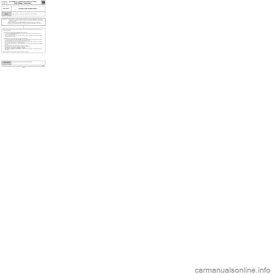
LOCKING OF ONE OR MORE WHEELSFault chart 4
REMINDER:Wheel locking on a vehicle equipped with ABS, or tyre squeal, considered by the customer
as locking, can be linked to a normal reaction of the system and should not be systematically
considered as a fault :
- locking is allowed below 3.75 mph ( 6 km/h) (the system will not provide regulation).
- Braking with ABS regulation under very bad road conditions (high degree of tyre squeal).
- - - - - - - - - - - - - - - - - - - - - - - - - - - - - - - - - - - - - - - - - -
Only consult this section after a complete check with the XR25 kit.NOTES
On the other hand, if there really is wheel locking on one or more wheels, lift the vehicle so the wheels can
be turned, and check :
- a possible incorrect connection in the speed sensor connection.
• Use operations #01, #02, #03 and #04 while turning the appropriate wheel and ensure the consis-
tency of the results obtained .
• If the value measured is zero, turn the other wheels to confirm a bad electrical connection of the sen-
sors and repair the wiring.
- A possible incorrect connection of the hydraulic assembly pipes.
• Use operations G03*, G04*, G05* and G06* while applying the brake and check for the ten cycles of
unlocking/locking on the wheel concerned (consult section "Aid").
• If the ten cycles do not occur on the wheel tested, (wheel remains locked), see if they occur on ano-
ther wheel (if a bad connection is confirmed: repair).
• If the ten cycles do not occur on a wheel and the pipes are correctly connected, replace the hydraulic
assembly.
• Check the condition of the ABS targets and that they conform.
• Also check the sensor/target air gap by rotating each of the wheels :
Front 0.13 mm < air gap over one rotation < 1.96 mm.
Rear 0.03 mm < air gap over one rotation < 2.4 mm (check only possible on vehicles with four-bar
rear axles).
If the fault persists after these checks, replace the hydraulic assembly.
38-24
Page 286 of 363
B76531.0
ELECTRONICALLY CONTROLLED HYDRAULIC SYSTEM
Fault finding - Fault chart 38
ABS BOSCH
5.3
AFTER REPAIR Carry out a road test, then a check with the XR25 kit.
yes
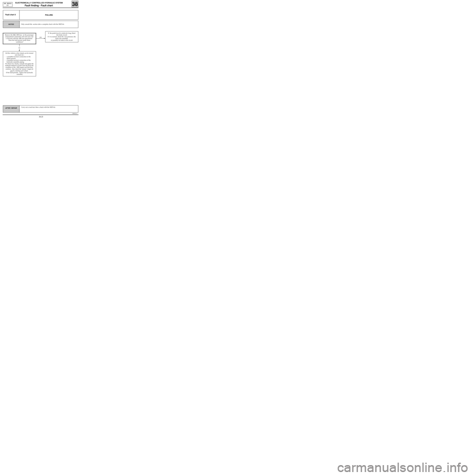
PULLINGFault chart 5
Only consult this section after a complete check with the XR25 kit.NOTES
Lift the vehicle so the wheels can be turned
and check for :
- a possible incorrect connection in the
speed sensors,
- a possible incorrect connection of the
hydraulic assembly piping.
For these two checks, consult and apply the
methods defined in Fault Chart 4.Check the
condition of the ABS targets and that they
conform. Also check the sensor/ target air
gap by rotating each wheel.
If the fault persists, replace the hydraulic
assembly.
If the pedal travel is relatively long, bleed
the brake circuit.
If it is normal, check the tyre pressure, the
front axle assembly
or possibly for leaks in the circuit.
no
Remove the 10A ABS fuse on the passenger
compartment connection unit and carry out
a road test with the ABS non-operational.
Does the fault persist under these
conditions?
38-25