air condition RENAULT KANGOO 1997 KC / 1.G Foult Finding - Injection Workshop Manual
[x] Cancel search | Manufacturer: RENAULT, Model Year: 1997, Model line: KANGOO, Model: RENAULT KANGOO 1997 KC / 1.GPages: 363
Page 9 of 363
DPCF01 1.0
LUCAS DIESEL INJECTION
Fault finding - Interpretation of XR25 bargraphs13
AFTER REPAIR
Fiche n° 60 1/2
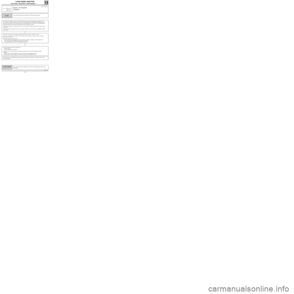
Bargraph 1 RH extinguished
Code present
1
Use bornier Elé. 1332 for any operations on the computer connector.NOTES
When communication is established, deal with any fault bargraphs which may be
illuminated.
Ensure that the XR25 is not the cause of the fault by trying to communicate with the computer on ano-
ther vehicle. If the XR25 is not the cause of the fault and dialogue is not established with another compu-
ter on the same vehicle, a faulty computer may be causing interference on the K and L fault finding lines.
Disconnect connections successively to determine which computer is at fault.
Check the ISO selector is on position S8, that you are using the latest XR25 cassette and the correct access
code (D34).
Check the battery voltage and carry out any necessary operations to ensure the correct voltage (U battery
> 10.5 volts).
Check the 15 Amp fuses on the engine connection unit have not blown (positions 3 and 4).
Check the connection and condition of the connections on the computer connector and the connection
R67 engine / dashboard.
Check the computer is correctly fed:
- Earth on track 2 of the computer connector (check the condition and tightness of the engine earth
strap and the engine earth MH near to the gearbox housing).
- + after ignition feed on track 1 of the computer connector.
Check the diagnostic socket is correctly fed:
- Earth on track 5.
- + before ignition feed on track 16.
Check and ensure the continuity and insulation of the lines in the connection diagnostic socket/
computer:
- Between track 10 of the computer connector and track 15 of the diagnostic socket.
- Between track 13 of the computer connector and track 7 of the diagnostic socket.
If fault finding is not established after these operations, replace the computer (consult the "Aid" section
for this operation).
13-5
Page 11 of 363
DPCF01 1.0
LUCAS DIESEL INJECTION
Fault finding - Interpretation of XR25 bargraphs13
AFTER REPAIRErase the computer memory (G0**), switch the ignition off, then carry out a road
test.
Finish the operation by checking using the XR25.
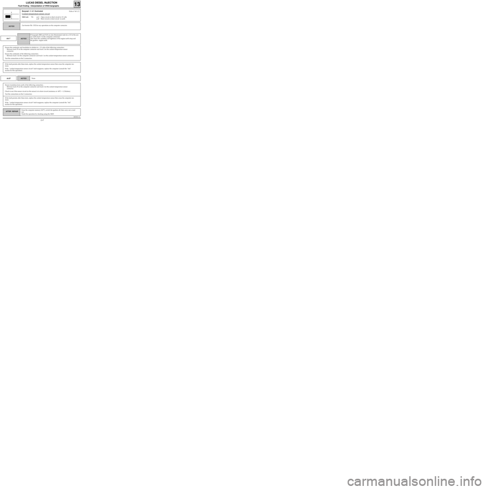
Bargraph 2 LH illuminated
Coolant temperature sensor circuit
XR25 aid:*02 :co.1 : Open circuit or short circuit to 12 volts
cc.0 : Short circuit or short circuit to earth
2
Use bornier Elé. 1332 for any operations on the computer connector.NOTES
Fiche n° 60 1/2
co.1
Ensure the continuity and insulation in relation to + 12 volts of the following connection :
- Between track 25 on the computer connector and track 2 on the coolant temperature sensor
connector.
Ensure the continuity of the following connection :
- Between track 3 on the computer connector and track 1 on the coolant temperature sensor connector.
Test the connections on the 2 connectors.
If bargraphs 2RH and 3LH are also illuminated, look for a CO of the sen-
sor earth (track 3 of the computer connector)
Also check the condition and tightness of the engine earth strap and
the gearbox engine earth.
NOTES
If the fault persists after these tests, replace the coolant temperature sensor then erase the computer me-
mory.
If the "coolant temperature sensor circuit" fault reappears, replace the computer (consult the "Aid"
section for this operation).
cc.0None NOTES
Ensure insulation from earth of the following connection :
- Between track 25 on the computer connector and track 2 on the coolant temperature sensor
connector.
Check to see if the sensor circuit (or the sensor) is in short circuit (resistance at 60°C = 1.2 Kohms).
Test the connections on the 2 connectors.
If the fault persists after these tests, replace the coolant temperature sensor then erase the computer me-
mory.
If the "coolant temperature sensor circuit" fault reappears, replace the computer (consult the "Aid"
section for this operation).
13-7
Page 15 of 363
DPCF01 1.0
LUCAS DIESEL INJECTION
Fault finding - Interpretation of XR25 bargraphs13
AFTER REPAIRErase the computer memory (G0**), switch the ignition off, then carry out a road
test.
Finish the operation by checking using the XR25.
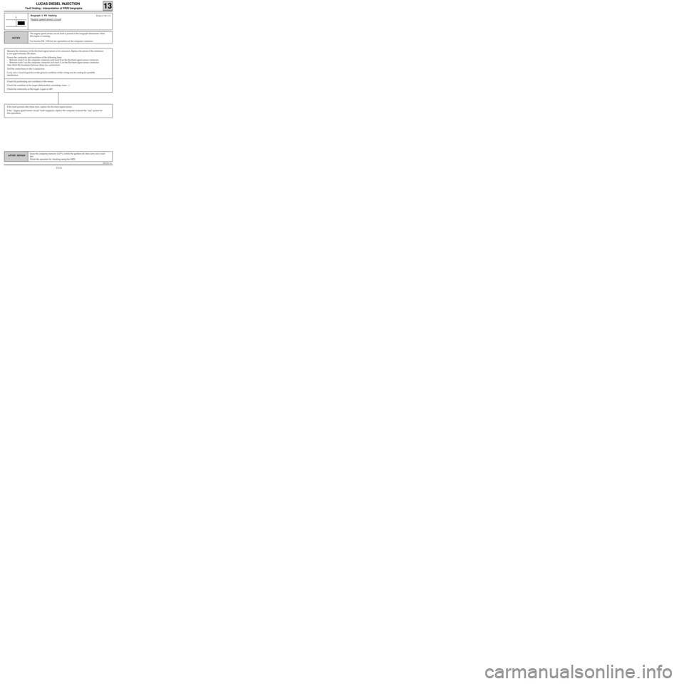
Bargraph 3 RH flashing
Engine speed sensor circuit3
The engine speed sensor circuit fault is present if the bargraph illuminates when
the engine is running.
Use bornier Elé. 1332 for any operations on the computer connector.
NOTES
Measure the resistance of the flywheel signal sensor at its connector. Replace the sensor if the resistance
is not approximately 250 ohms.
Ensure the continuity and insulation of the following lines:
- Between track 8 on the computer connector and track B on the flywheel signal sensor connector.
- Between track 3 on the computer connector and track A on the flywheel signal sensor connector.
Also check the insulation between these two connections.
Test the connections on the 2 connectors.
Carry out a visual inspection of the general condition of the wiring and its routing for possible
interference.
Fiche n° 60 1/2
Check the positioning and condition of the sensor.
Check the condition of the target (deformation, mounting, noise....).
Check the conformity of the target: 2 gaps at 180°.
If the fault persists after these tests, replace the flywheel signal sensor.
If the "engine speed sensor circuit" fault reappears, replace the computer (consult the "Aid" section for
this operation).
13-11
Page 18 of 363
DPCF01 1.0
LUCAS DIESEL INJECTION
Fault finding - Interpretation of XR25 bargraphs13
AFTER REPAIRErase the computer memory (G0**), switch the ignition off, then carry out a road
test.
Finish the operation by checking using the XR25.
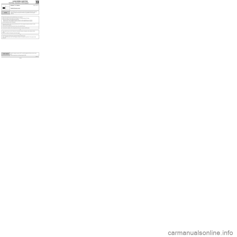
Bargraph 5 LH flashing
Needle lift sensor circuit
5
The needle lift sensor circuit fault is present if the bargraph illuminates when the
engine is running. Use bornier Elé. 1332 for any operations on the computer
connector.
NOTES
Measure the resistance of the needle lift sensor at its connector.
Replace the injector with the sensor if the resistance is not approximately 105 ohms.
Ensure the continuity of the following connections:
- Between track 7 on the computer connector and track 1 on the needle lift sensor connector.
- Between track 3 on the computer connector and track 2 on the needle lift sensor connector.
Test the connections on the 2 connectors.
Fiche n° 60 1/2
Ensure the insulation of the connection between track 7 on the computer connector and track 1 on the
needle lift sensor connector .
Also ensure the insulation between the 2 lines on the needle lift sensor.
Also check the condition of the wiring between the sensor connector and the sensor.
If the fault persists after these tests, replace the injector with the sensor.
If the "needle lift sensor circuit" fault reappears, replace the computer (consult the "Aid" section for this
operation).
The "needle lift sensor circuit" fault may be connected to absence of injection at the cylinder with the
sensor.
Check the condition of the injector and its fuel supply.
13-14
Page 21 of 363
DPCF01 1.0
LUCAS DIESEL INJECTION
Fault finding - Interpretation of XR25 bargraphs13
AFTER REPAIRErase the computer memory (G0**), switch the ignition off, then carry out a road
test.
Finish the operation by checking using the XR25.
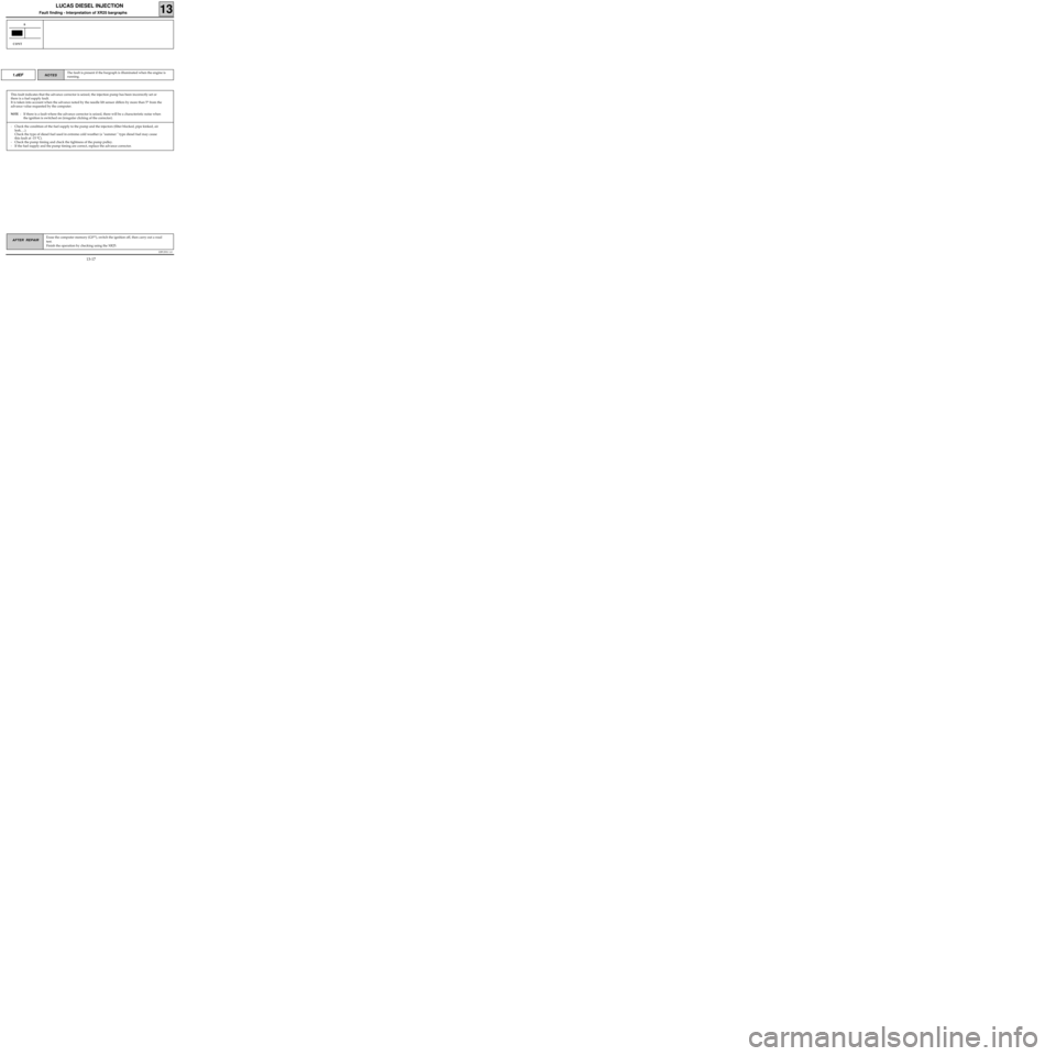
1.dEF
This fault indicates that the advance corrector is seized, the injection pump has been incorrectly set or
there is a fuel supply fault.
It is taken into account when the advance noted by the needle lift sensor differs by more than 5° from the
advance value requested by the computer.
NOTE : If there is a fault where the advance corrector is seized, there will be a characteristic noise when
the ignition is switched on (irregular clicking of the corrector).
The fault is present if the bargraph is illuminated when the engine is
running.NOTES
6
CONT
- Check the condition of the fuel supply to the pump and the injectors (filter blocked, pipe kinked, air
leak, ...).
Check the type of diesel fuel used in extreme cold weather (a "summer " type diesel fuel may cause
this fault at -15 °C).
- Check the pump timing and check the tightness of the pump pulley.
- If the fuel supply and the pump timing are correct, replace the advance corrector.
13-17
Page 27 of 363
DPCF01 1.0
LUCAS DIESEL INJECTION
Fault finding - Interpretation of XR25 bargraphs13
AFTER REPAIRErase the computer memory (G0**), switch the ignition off, then carry out a road
test.
Finish the operation by checking using the XR25.
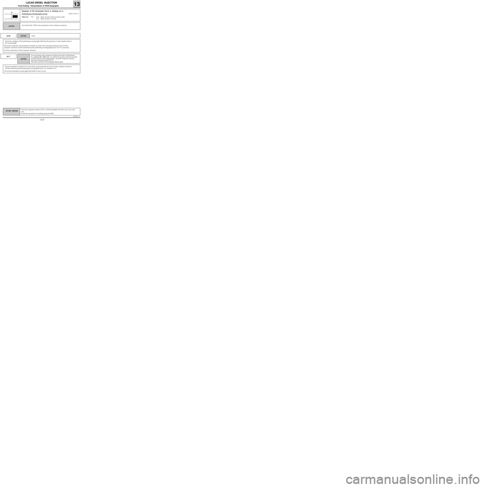
Bargraph 10 RH illuminated (Co.0) or flashing (cc.1)
Preheating warning light circuit
XR25 aid:*30 :cc.0 : Open circuit or short circuit to earth
cc.1 : Short circuit to 12 volts
10Fiche n° 60 1/2
co.0
Check the condition of the preheating warning light bulb then the presence of +after ignition feed at
the warning light.
Ensure the continuity and insulation in relation to earth of the connection between track 9 of the
computer connector and the instrument panel preheating warning light (track 5 on CY connector).
Test the connections on the computer connector.
None NOTES
cc.1
Ensure insulation in relation to 12 volts of the connection between track 9 of the computer connector
and the instrument panel preheating warning light (track 5 on connector CY).
Test at the preheating warning light bulb (bulb in short circuit).
Use bornier Elé. 1332 for any operations on the computer connector.NOTES
Even if present at the moment of testing, this fault is still declared
by a flashing BG 10RH side. To confirm its presence and the necessity
of following the fault finding below, erase the computer memory
then start command mode G21*2*.
The fault is present if the bargraph flashes again.
NOTES
13-23
Page 28 of 363
DPCF01 1.0
LUCAS DIESEL INJECTION
Fault finding - Interpretation of XR25 bargraphs13
AFTER REPAIRErase the computer memory (G0**), switch the ignition off, then carry out a road
test.
Finish the operation by checking using the XR25.
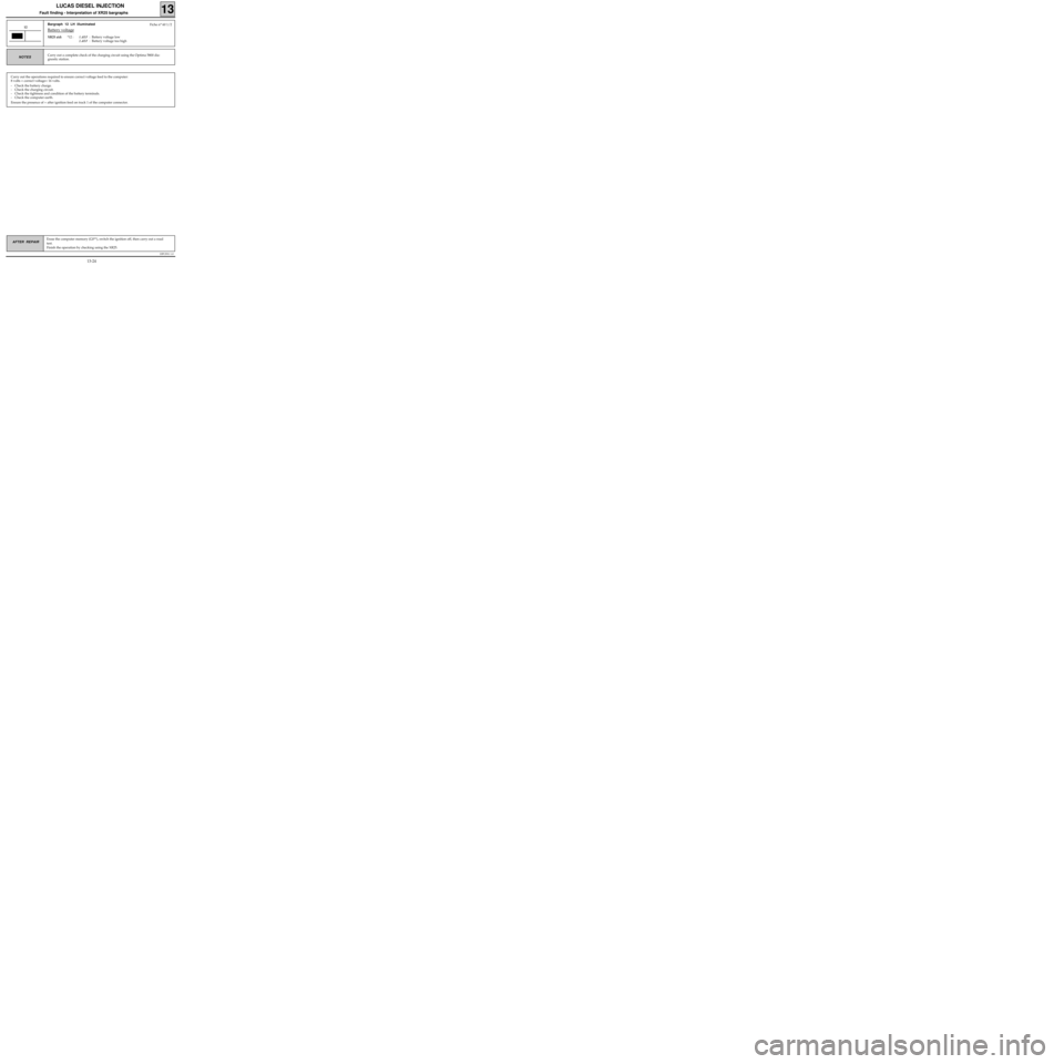
Bargraph 12 LH illuminated
Battery voltage
XR25 aid:*12 :1.dEF : Battery voltage low
2.dEF : Battery voltage too high
12
Carry out a complete check of the charging circuit using the Optima 5800 dia-
gnostic station.NOTES
Carry out the operations required to ensure correct voltage feed to the computer:
8 volts < correct voltage< 16 volts.
- Check the battery charge.
- Check the charging circuit.
- Check the tightness and condition of the battery terminals.
- Check the computer earth.
Ensure the presence of + after ignition feed on track 1 of the computer connector.
Fiche n° 60 1/2
13-24
Page 30 of 363
DPCF01 1.0
LUCAS DIESEL INJECTION
Fault finding - Interpretation of XR25 bargraphs13
AFTER REPAIRErase the computer memory (G0**), switch the ignition off, then carry out a road
test.
Finish the operation by checking using the XR25.
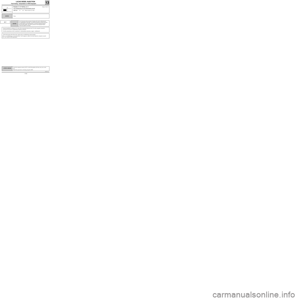
Bargraph 13 LH flashing (cc.1)
Air conditioning cut out information circuit
XR25 aid:*13 :cc.1 : Short circuit to 12 volts
13
None NOTES
Fiche n° 60 1/2
cc.1
Ensure insulation in relation to 12 volts of the connection between track 19 on the computer connector
and track 18 on the air conditioning computer connector.
Test the connections on the 2 connectors (+ intermediate connection engine / dashboard).
Even if present at the moment of testing, this fault is still declared
by a flashing BG 13LH side. To confirm its presence and the necessity
of following the fault finding below, erase the computer memory
then start the engine. The fault is present if the bargraph flashes
when the engine is running.
NOTES
If the fault persists after these tests, replace the air conditioning control module.
If the "air conditioning cut out information "fault reappears, replace the diesel injection computer (consult
the "Aid" section for this operation).
13-26
Page 32 of 363
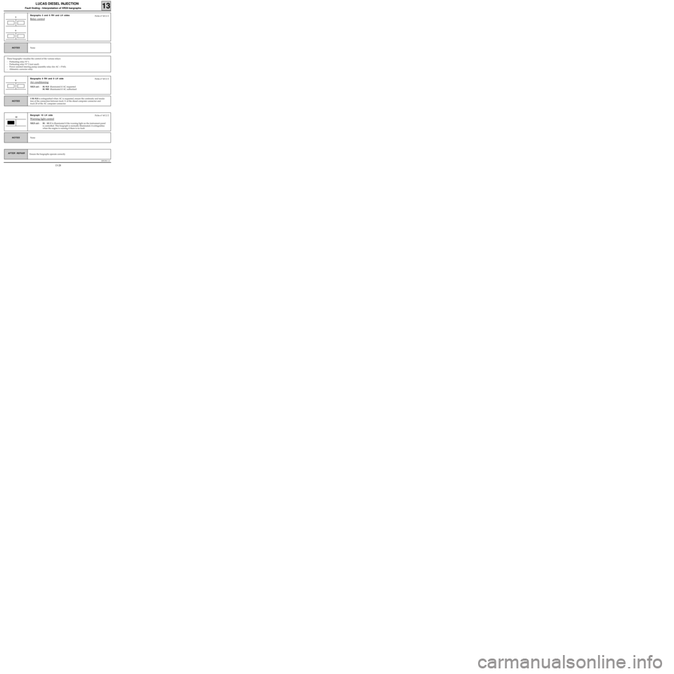
Bargraphs 9 RH and 9 LH side
Air conditioning
XR25 aid :BG 9LH illuminated if AC requested
BG 9RH illuminated if AC authorised
DPCF01 1.0
LUCAS DIESEL INJECTION
Fault finding - Interpretation of XR25 bargraphs13
AFTER REPAIR
Bargraphs 5 and 6 RH and LH sides
Relay control5
None NOTES
These bargraphs visualise the control of the various relays:
- Preheating relay N° 1.
- Preheating relay N° 2 (not used).
- Power assisted steering pump assembly relay (for AC + PAS).
- Altimetric corrector relay.
Fiche n° 60 2/2
6
Ensure the bargraphs operate correctly
9Fiche n° 60 2/2
If
BG 9LH is extinguished when AC is requested, ensure the continuity and insula-
tion of the connection between track 11 of the diesel computer connector and
track 20 of the AC computer connector.
NOTES
Bargraph 10 LH side
Warning light control
XR25 aid :BG 10LH is illuminated if the warning light on the instrument panel
is controlled. This bargraph is normally illuminated; it extinguishes
when the engine is running if there is no fault.
10Fiche n° 60 2/2
None
NOTES
13-28
Page 34 of 363
DPCF01 1.0
LUCAS DIESEL INJECTION
Fault finding - Interpretation of XR25 bargraphs13
AFTER REPAIR
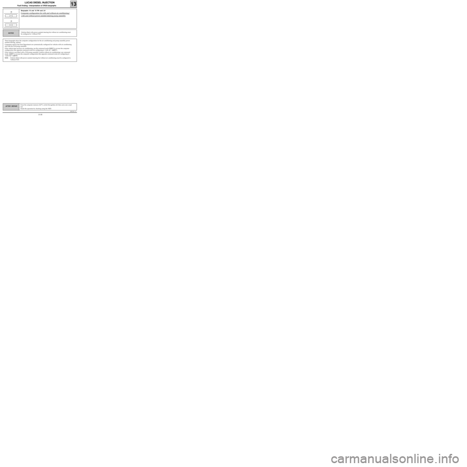
Bargraphs 18 and 19 RH and LH
Computer configuration for with and without air conditioning/
with and without power assisted steering pump assembly
18
Vehicles fitted with power assisted steering but without air conditioning must
be configured to "without PAS".NOTES
These bargraphs show the computer configuration for the air conditioning and pump assembly power
assisted steering options.
Computers sold by the Parts Department are systematically configured for vehicles with air conditioning
and with the PAS pump assembly.
If the vehicle does not have air conditioning, use the command mode G50*4* to reverse the computer
configuration (the opposite command exists for configuring to "with AC": G50*3*).
If the vehicle is not fitted with a PAS pump assembly (vehicle without air conditioning), use command
mode G50*9* to reverse the computer configuration (the opposite command exists for configuring to
"with PAS": G50*8*).
NOTE : Vehicles fitted with power assisted steering but without air conditioning must be configured to
"without PAS".
19
Erase the computer memory (G0**), switch the ignition off, then carry out a road
test.
Finish the operation by checking using the XR25.
13-30