ESP RENAULT KANGOO 1997 KC / 1.G Sheet Metal Work Owner's Manual
[x] Cancel search | Manufacturer: RENAULT, Model Year: 1997, Model line: KANGOO, Model: RENAULT KANGOO 1997 KC / 1.GPages: 255
Page 113 of 255
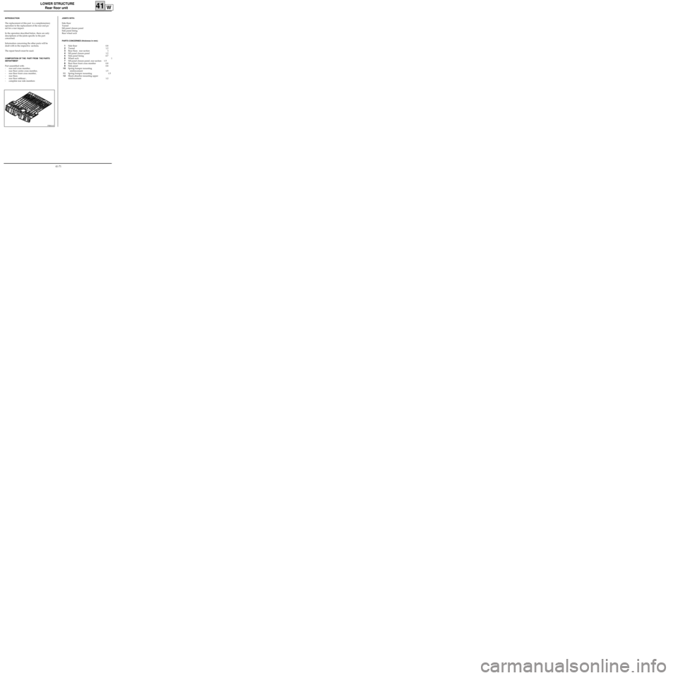
LOWER STRUCTURE
Rear floor unit
41W
PRB4143
INTRODUCTION
The replacement of this part is a complementary
operation to the replacement of the rear end pa-
nel for a rear impact.
In the operation described below, there are only
descriptions of the joints specific to the part
concerned.
Information concerning the other parts will be
dealt with in the respective sections.
The repair bench must be used.
COMPOSITION OF THE PART FROM THE PARTS
DEPARTMENT
Part assembled with:
- rear end cross member,
- rear floor centre cross member,
- rear floor front cross member,
- rear floor,
- rear floor stiffener ,
- complete rear side members
JOINTS WITH:
Side floor
Tunnel
Sill panel closure panel
Side panel lining
Rear wheel arch
PARTS CONCERNED (thickness in mm):
1Side floor 0.8
2Tunnel 1.2
3Rear floor, rear section 1
4Sill panel closure panel 1.2
5Side panel lining 0.7
6Wheel arch 1
7Sill panel closure panel, rear section 1.5
8Rear floor front cross member 0.8
9Side panel 0.8
10Spring bumper mounting
reinforcement 1.5
11Spring bumper mounting 1.5
12Shock absorber mounting upper
reinforcement 1.2
41-71
Page 128 of 255
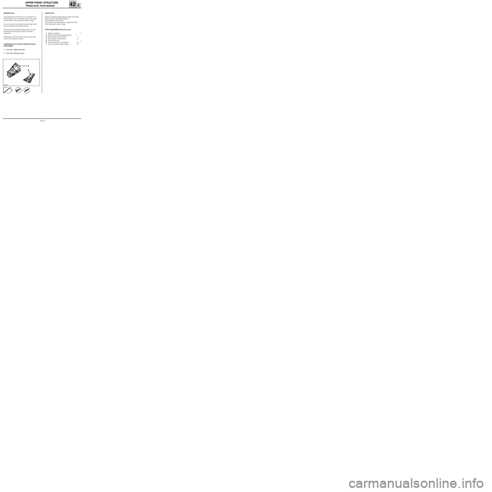
UPPER FRONT STRUCTURE
Wheel arch, front section
42E
PRB4212
INTRODUCTION
The replacement of this part is an operation for a
frontal impact and is complementary to the repla-
cement of the cowl side panel (pillar lining).
It can be carried out partially from the right hand
side (see diagram and method below).
In the operation described below there are only
descriptions of the joints specific to the part
concerned.
Information concerning other parts will be dealt
with in the respective section.
COMPOSITION OF THE PART FROM THE PARTS
DEPARTMENT
1 - Part only (right hand side).
2 - Part only (left hand side).
JOINTS WITH :
Engine mounting height adjuster (right hand side)
Shock absorber cup height adjuster
Side member closure panel
Front end lower cross member (right hand side)
Cowl side panel (pillar lining)
PARTS CONCERNED (thickness in mm):
1Engine mounting 2
2Shock absorber cup height adjuster 2
3Side member closure panel 1
4Side member, front section 1.5
5Front wheel arch 1
6Front end lower cross member 1.5
7Cowl side panel (pillar lining) 1.5
or
42-12
Page 133 of 255
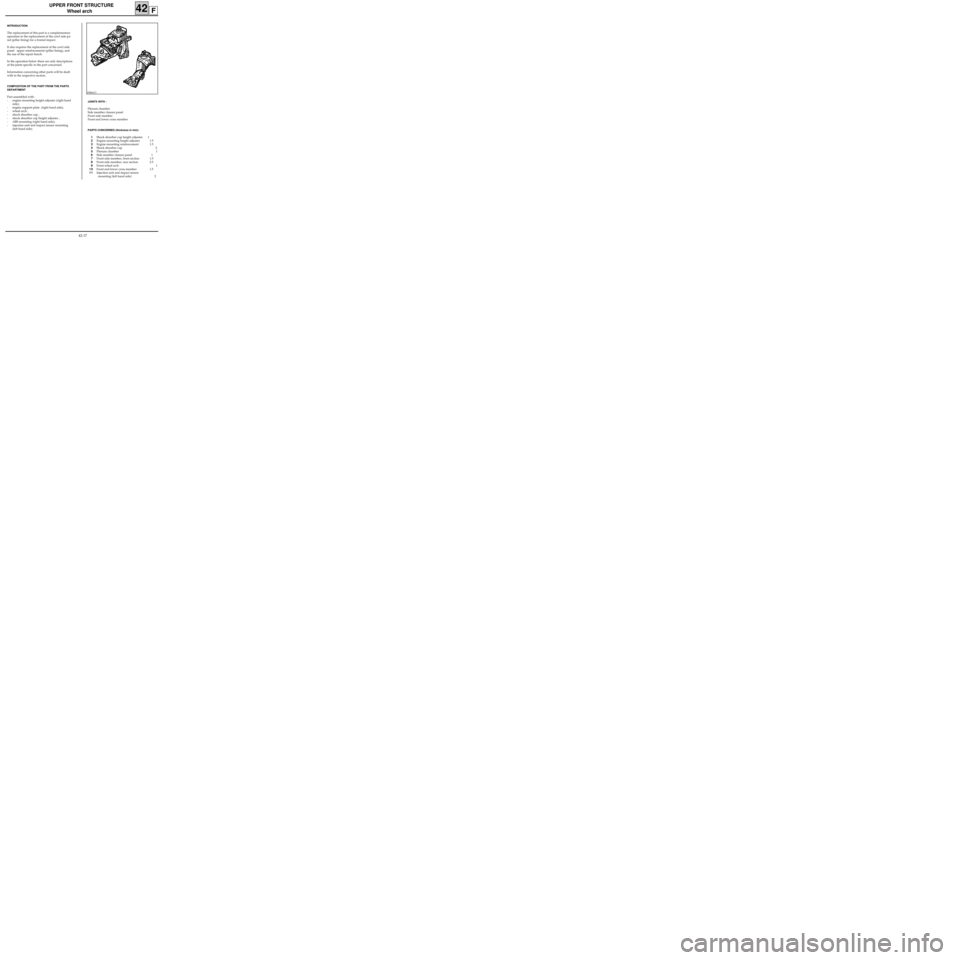
UPPER FRONT STRUCTURE
Wheel arch
42F
PRB4213
INTRODUCTION
The replacement of this part is a complementary
operation to the replacement of the cowl side pa-
nel (pillar lining) for a frontal impact.
It also requires the replacement of the cowl side
panel upper reinforcements (pillar lining), and
the use of the repair bench.
In the operation below there are only descriptions
of the joints specific to the part concerned.
Information concerning other parts will be dealt
with in the respective section.
COMPOSITION OF THE PART FROM THE PARTS
DEPARTMENT
Part assembled with :
- engine mounting height adjuster (right hand
side),
- engine support plate (right hand side),
- wheel arch ,
- shock absorber cup ,
- shock absorber cup height adjuster ,
- ABS mounting (right hand side),
- injection unit and impact sensor mounting
(left hand side).
JOINTS WITH :
Plenum chamber
Side member closure panel
Front side member
Front end lower cross member
PARTS CONCERNED (thickness in mm):
1Shock absorber cup height adjuster 1
2Engine mounting height adjuster 1.5
3Engine mounting reinforcement 1.5
4Shock absorber cup 2
5Plenum chamber 1
6Side member closure panel 1
7Front side member, front section 1.5
8Front side member, rear section 2.5
9Front wheel arch 1
10Front end lower cross member 1.5
11Injection unit and impact sensor
mounting (left hand side) 2
42-17
Page 140 of 255
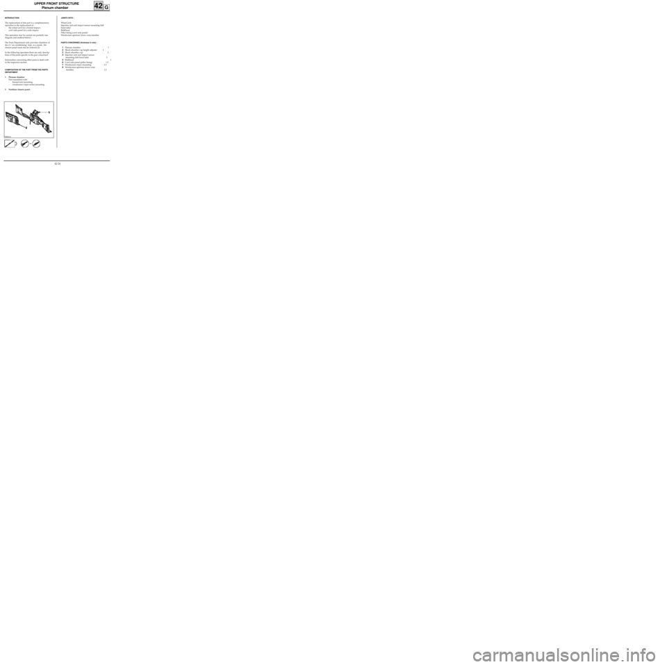
UPPER FRONT STRUCTURE
Plenum chamber
42G
PRB4214
INTRODUCTION
The replacement of this part is a complementary
operation to the replacement of :
- the wheel arch for a frontal impact,
- cowl side panel for a side impact.
This operation may be carried out partially (see
diagram and method below).
The Parts Department only provides chambers of
the (1) "air conditioning" type, as a result, the
closure panel must also be ordered (2).
In the following operation there are only descrip-
tions of the joints specific to the part concerned.
Information concerning other parts is dealt with
in the respective section.
COMPOSITION OF THE PART FROM THE PARTS
DEPARTMENT
1 Plenum chamber
Part assembled with :
- bonnet lock mounting,
- windscreen wiper motor mounting.
2 Partition closure panel.
JOINTS WITH :
Wheel arch
Injection unit and impact sensor mounting (left
hand side)
Bulkhead
Pillar lining (cowl side panel)
Windscreen aperture lower cross member
PARTS CONCERNED (thickness in mm) :
1Plenum chamber 1
2Shock absorber cup height adjuster 1
3Shock absorber cup 2
4Injection unit and impact sensor
mounting (left hand side) 2
5Bulkhead 1
6Cowl side panel (pillar lining) 1.5
7Windscreen wiper mounting 1.5
8Windscreen aperture lower cross
member 1.2
or
42-24
Page 144 of 255
UPPER FRONT STRUCTURE
Windscreen aperture lower cross member
42H
PRB4215
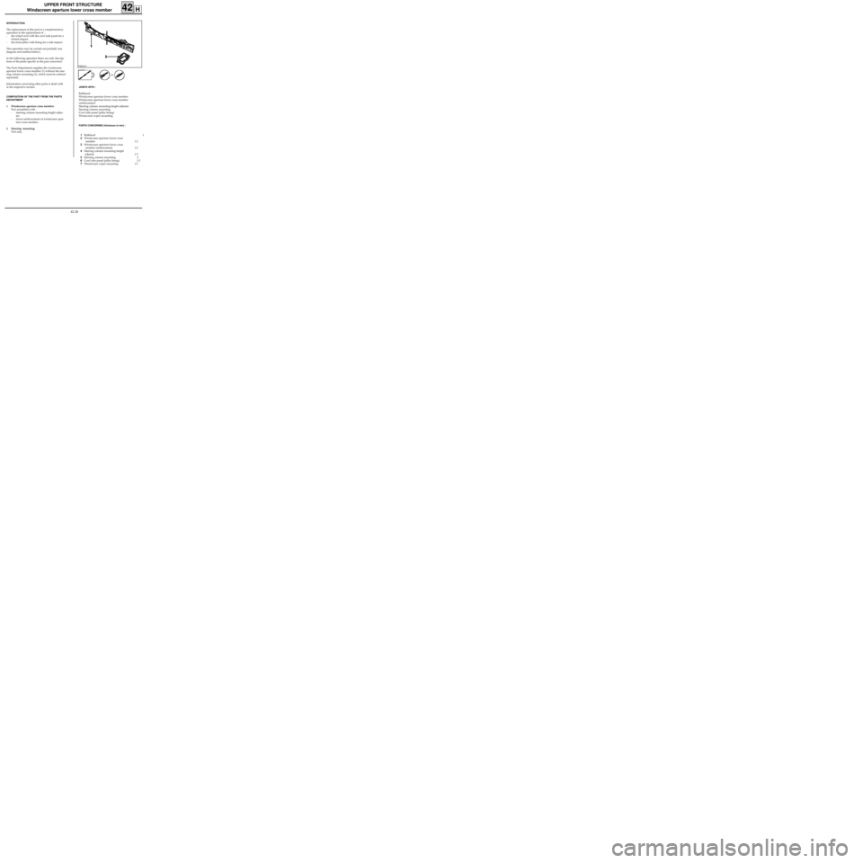
INTRODUCTION
The replacement of this part is a complementary
operation to the replacement of :
- the wheel arch with the cowl side panel for a
frontal impact,
- the front pillar with lining for a side impact.
This operation may be carried out partially (see
diagram and method below).
In the following operation there are only descrip-
tions of the joints specific to the part concerned.
The Parts Department supplies the windscreen
aperture lower cross member (1) without the stee-
ring column mounting (2), which must be ordered
separately.
Information concerning other parts is dealt with
in the respective section.
COMPOSITION OF THE PART FROM THE PARTS
DEPARTMENT
1 Windscreen aperture cross member
Part assembled with :
- steering column mounting height adjus-
ter,
- lower reinforcement of windscreen aper-
ture cross member.
2 Steering mounting
Part only.
JOINTS WITH :
Bulkhead
Windscreen aperture lower cross member
Windscreen aperture lower cross member
reinforcement
Steering column mounting height adjuster
Steering column mounting
Cowl side panel (pillar lining)
Windscreen wiper mounting
PARTS CONCERNED (thickness in mm) :
1Bulkhead 1
2Windscreen aperture lower cross
member 1.2
3Windscreen aperture lower cross
member reinforcement 1.2
4Steering column mounting height
adjuster 1.5
5Steering column mounting 2
6Cowl side panel (pillar lining) 1.5
7Windscreen wiper mounting 1.5or
42-28
Page 150 of 255
UPPER FRONT STRUCTURE
Bulkhead
42J
PRB4217
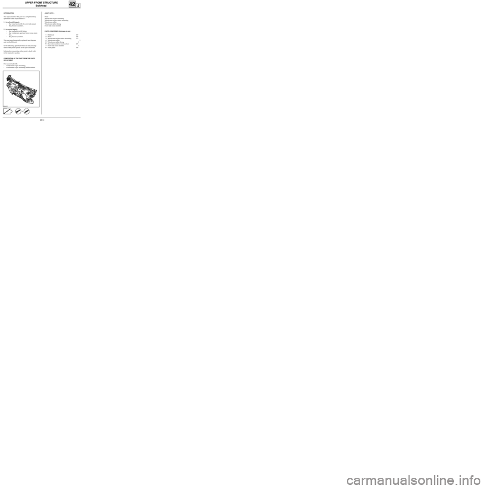
INTRODUCTION
The replacement of this part is a complementary
operation to the replacement of :
1 - for a frontal impact :
- the wheel arch with the cowl side panel,
- the plenum chamber ,
2 - for a side impact:
- the front pillar with lining,
- the windscreen aperture lower cross mem-
ber,
- the plenum chamber .
This part may be partially replaced (see diagram
and method below).
In the following operation there are only descrip-
tions of the joints specific to the part concerned.
Information concerning other parts is dealt with
in the respective section.
COMPOSITION OF THE PART FROM THE PARTS
DEPARTMENT
Part assembled with :
- windscreen wiper mounting,
- windscreen wiper mounting reinforcement.
JOINTS WITH :
Floor
Windscreen wiper mounting
Windscreen wiper motor mounting
Windscreen pillar
Windscreen pillar lining
Front side cross member
PARTS CONCERNED (thickness in mm) :
1Bulkhead 0.7
2Floor 0.8
3Windscreen wiper motor mounting 1.5
4Windscreen pillar 1
5Windscreen pillar lining 1
6Rear side member, front section 2.5
7Front side cross member 1
8Front pillar 0.8
or
42-34
Page 155 of 255
UPPER SIDE STRUCTURE
Front pillar
43A
PRB4311
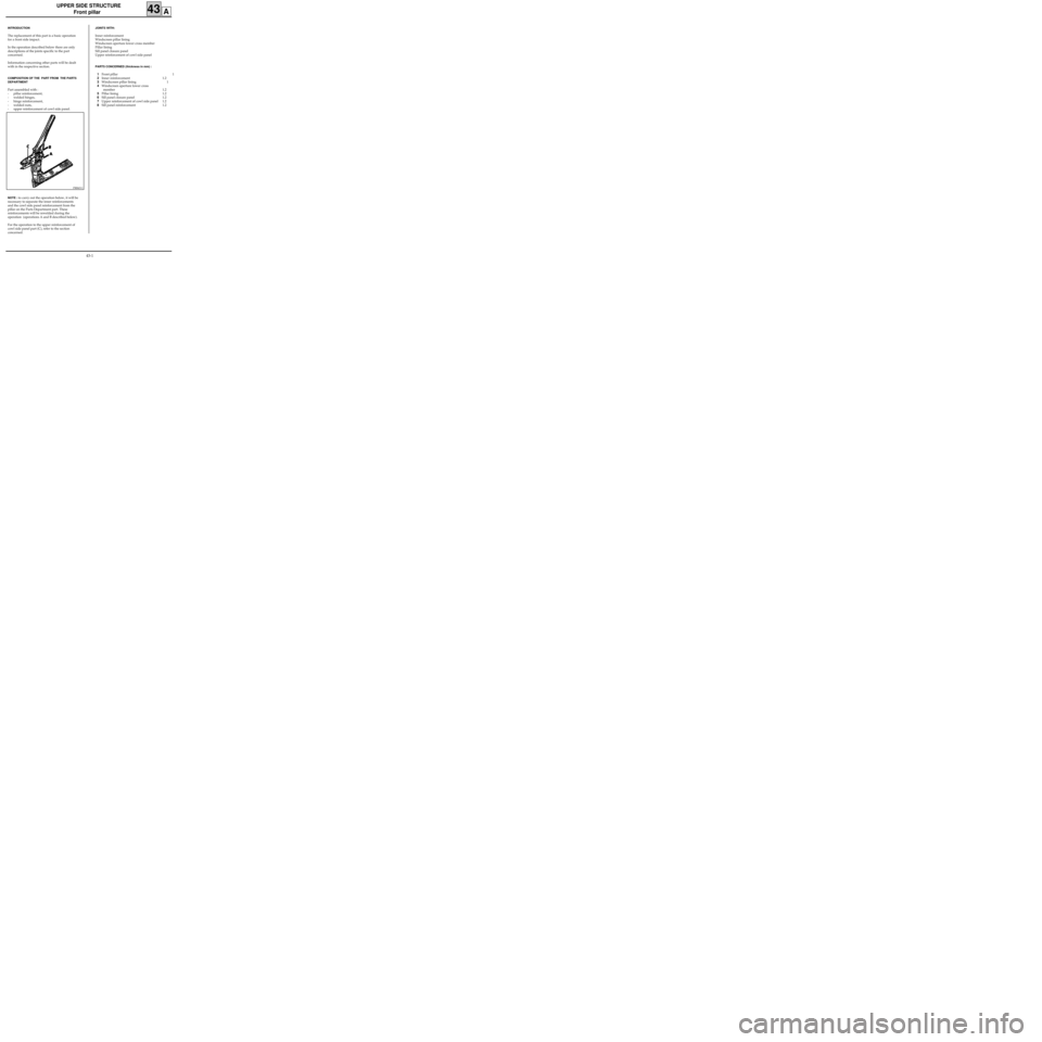
INTRODUCTION
The replacement of this part is a basic operation
for a front side impact.
In the operation described below there are only
descriptions of the joints specific to the part
concerned.
Information concerning other parts will be dealt
with in the respective section.
COMPOSITION OF THE PART FROM THE PARTS
DEPARTMENT
Part assembled with :
- pillar reinforcement,
- welded hinges,
- hinge reinforcement,
- welded nuts,
- upper reinforcement of cowl side panel.
NOTE : to carry out the operation below, it will be
necessary to separate the inner reinforcements
and the cowl side panel reinforcement from the
pillar on the Parts Department part. These
reinforcements will be rewelded during the
operation (operations A and B described below).
For the operation to the upper reinforcement of
cowl side panel part (C), refer to the section
concerned.
JOINTS WITH:
Inner reinforcement
Windscreen pillar lining
Windscreen aperture lower cross member
Pillar lining
Sill panel closure panel
Upper reinforcement of cowl side panel
PARTS CONCERNED (thickness in mm) :
1Front pillar 1
2Inner reinforcement 1.2
3Windscreen pillar lining 1
4Windscreen aperture lower cross
member 1.2
5Pillar lining 1.2
6Sill panel closure panel 1.2
7Upper reinforcement of cowl side panel 1.2
8Sill panel reinforcement 1.2
43-1
Page 160 of 255

UPPER SIDE STRUCTURE
Windscreen aperture pillar
43B
INTRODUCTION
The replacement of this part is a complementary
operation to the replacement of the front pillar
for a front side impact.
In the operation described below there are only
descriptions of the joints specific to the part
concerned.
Information concerning other parts will be dealt
with in the respective section.
COMPOSITION OF THE PART FROM THE PARTS
DEPARTMENT
Part assembled with aerial cable guide.
PRB4312
JOINTS WITH:
Roof front cross member
Roof
Body side
Roof stretcher
PARTS CONCERNED (thickness in mm) :
1Windscreen pillar lining 1
2Roof front cross member 0.8
3Roof 0.7
4Body side 1
5Roof stretcher 0.7
6Centre pillar upper reinforcement 1.2
7Body side lining 0.7
43-6
Page 163 of 255
UPPER SIDE STRUCTURE
Front pillar lining / Cowl side panel
43C
PRB4313
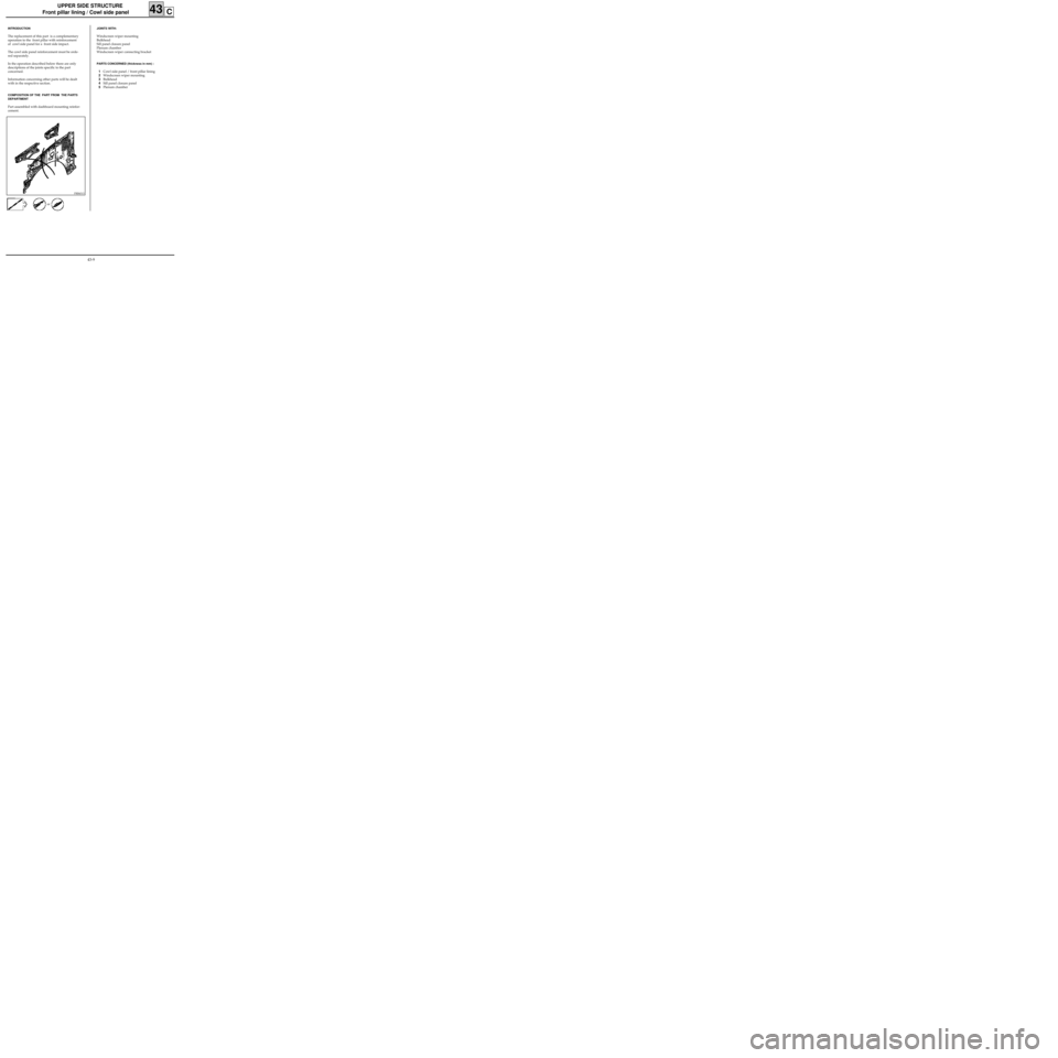
INTRODUCTION
The replacement of this part is a complementary
operation to the front pillar with reinforcement
of cowl side panel for a front side impact.
The cowl side panel reinforcement must be orde-
red separately.
In the operation described below there are only
descriptions of the joints specific to the part
concerned.
Information concerning other parts will be dealt
with in the respective section.
COMPOSITION OF THE PART FROM THE PARTS
DEPARTMENT
Part assembled with dashboard mounting reinfor-
cement.
JOINTS WITH:
Windscreen wiper mounting
Bulkhead
Sill panel closure panel
Plenum chamber
Windscreen wiper connecting bracket
PARTS CONCERNED (thickness in mm) :
1Cowl side panel / front pillar lining
2Windscreen wiper mounting
3Bulkhead
4Sill panel closure panel
5Plenum chamber
or
43-9
Page 168 of 255
UPPER SIDE STRUCTURE
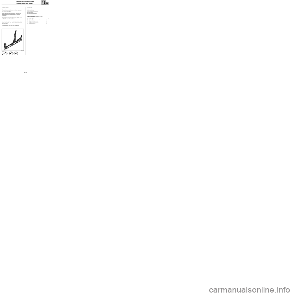
Centre pillar / sill panel
43D
PRB4314
INTRODUCTION
The replacement of this part is a basic operation
for a front side impact.
In the operation described below there are only
descriptions of the joints specific to the part
concerned.
Information concerning other parts will be dealt
with in the respective section.
COMPOSITION OF THE PART FROM THE PARTS
DEPARTMENT
Part assembled with side door rail guides.
or
JOINTS WITH:
Body side lining
Centre pillar reinforcement
Sill panel lining
Sill panel reinforcement
PARTS CONCERNED (thickness in mm) :
1Centre pillar 1
2Centre pillar reinforcement 1.2
3Sill panel closure panel 1.2
4Sill panel reinforcement 1.2
5Body side lining 0.8
43-14