sensor RENAULT SCENIC 2007 J84 / 2.G Power Assisted Steering User Guide
[x] Cancel search | Manufacturer: RENAULT, Model Year: 2007, Model line: SCENIC, Model: RENAULT SCENIC 2007 J84 / 2.GPages: 59, PDF Size: 0.19 MB
Page 28 of 59
POWER-ASSISTED STEERING
Fault finding – Conformity check
36B
36B-28V5 MR-372-J84-36B000$528_fra.mif
EPAS
Vdiag no.: 05, 09,
0DPOWER-ASSISTED STEERING
Fault finding – Conformity check
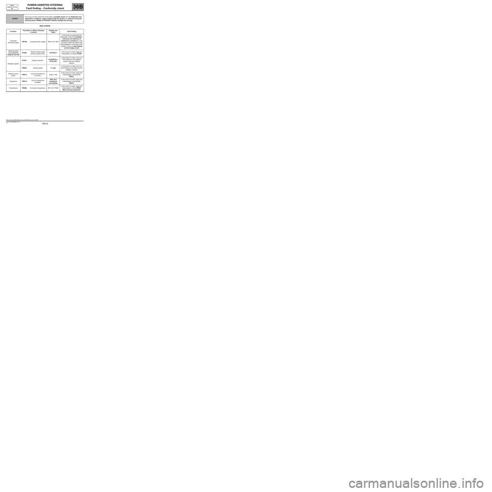
MAIN SCREEN
NOTESOnly carry out this conformity check after a complete check with the diagnostic tool.
Application conditions: engine stopped with the ignition on, without moving the
steering wheel, WHEELS STRAIGHT AHEAD (straight line driving).
FunctionParameter or Status Checked
or ActionDisplay and
notes Fault finding
Computer
electrical supplyPR108:Computer feed voltage10 V < X < 13 VIn the event of a fault with this
parameter, check the insulation,
continuity and absence of
interference resistance on the
computer earths and feeds (see
wiring diagrams). If the fault is still
present, carry out fault finding
on the charge circuit.
Steering wheel
angle (only for
Vdiag 05 and 09)ET020:Steering wheel angle
sensor programmingSTATUS 4In the event of a fault, apply the
interpretation of status ET020.
Multiplex signalsET023:Engine operationSTOPPED or
STALLEDIn the event of a fault, carry out
fault finding on the injection
system and the multiplex
network.
PR003:Vehicle speed0 mphIn the event of a fault, carry out
fault finding on the ABS and the
multiplex network.
Steering motor
powerPR012:Current absorbed by
the motor0 A (+ 1 A)In the event of a fault, apply the
interpretation of parameter
PR012.
AssistancePR014:Level of assistance
available100% (but
assistance
unavailable)In the event of a fault, apply the
interpretation of parameter
PR014.
TemperaturePR008:Computer temperature0˚C < X < 75˚CIn the event of a fault, apply the
interpretation of fault DF001
Motor thermal protection.
DAE_V05_CCONF/DAE_V09_CCONF/DAE_V0D_CCONF
MR-372-J84-36B000$528_fra.mif
Page 29 of 59
POWER-ASSISTED STEERING
Fault finding – Conformity check
36B
36B-29V5 MR-372-J84-36B000$528_fra.mif
EPAS
Vdiag no.: 05, 09,
0D
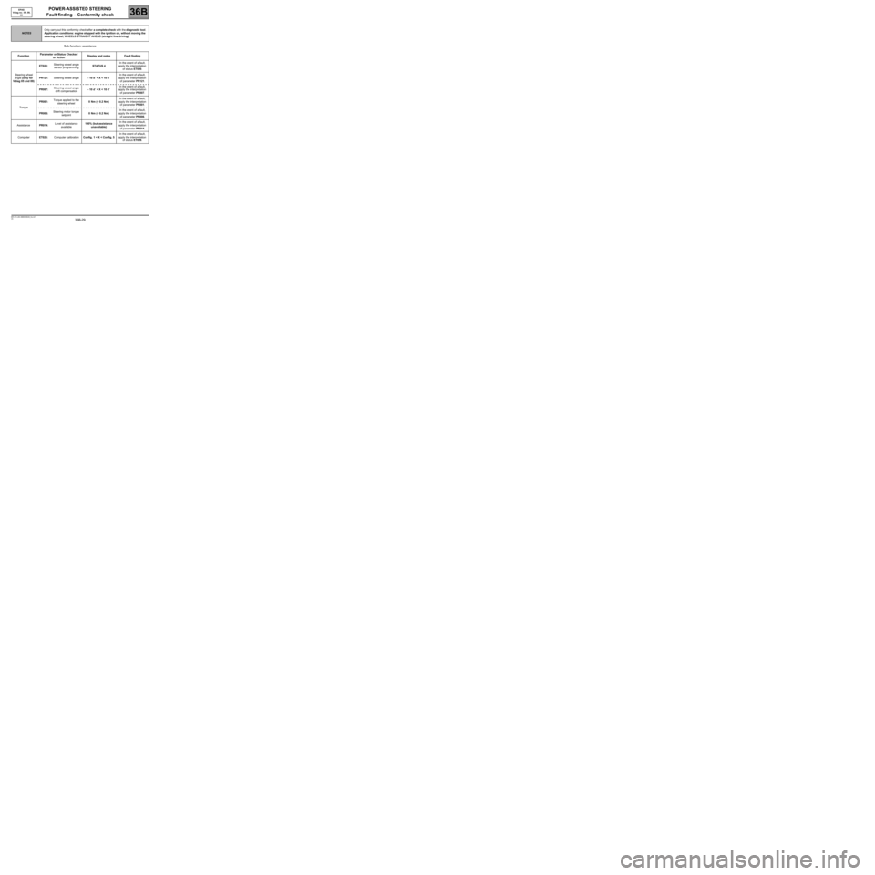
Sub-function: assistance
NOTESOnly carry out this conformity check after a complete check with the diagnostic tool.
Application conditions: engine stopped with the ignition on, without moving the
steering wheel, WHEELS STRAIGHT AHEAD (straight line driving).
FunctionParameter or Status Checked
or ActionDisplay and notes Fault finding
Steering wheel
angle (only for
Vdiag 05 and 09)ET020:Steering wheel angle
sensor programmingSTATUS 4In the event of a fault,
apply the interpretation
of status ET020.
PR121:Steering wheel angle- 10 d˚ < X < 10 d˚In the event of a fault,
apply the interpretation
of parameter PR121.
PR007:Steering wheel angle
drift compensation- 10 d˚ < X < 10 d˚In the event of a fault,
apply the interpretation
of parameter PR007.
TorquePR001:Torque applied to the
steering wheel0 Nm (+ 0.2 Nm)In the event of a fault,
apply the interpretation
of parameter PR001.
PR006:Steering motor torque
setpoint0 Nm (+ 0.2 Nm)In the event of a fault,
apply the interpretation
of parameter PR006.
AssistancePR014:Level of assistance
available100% (but assistance
unavailable)In the event of a fault,
apply the interpretation
of parameter PR014.
ComputerET026:Computer calibrationConfig. 1 < X < Config. 5In the event of a fault,
apply the interpretation
of status ET026.
Page 32 of 59
POWER-ASSISTED STEERING
Fault finding – Conformity check
36B
36B-32V5 MR-372-J84-36B000$528_fra.mif
EPAS
Vdiag no.: 05, 09,
0D
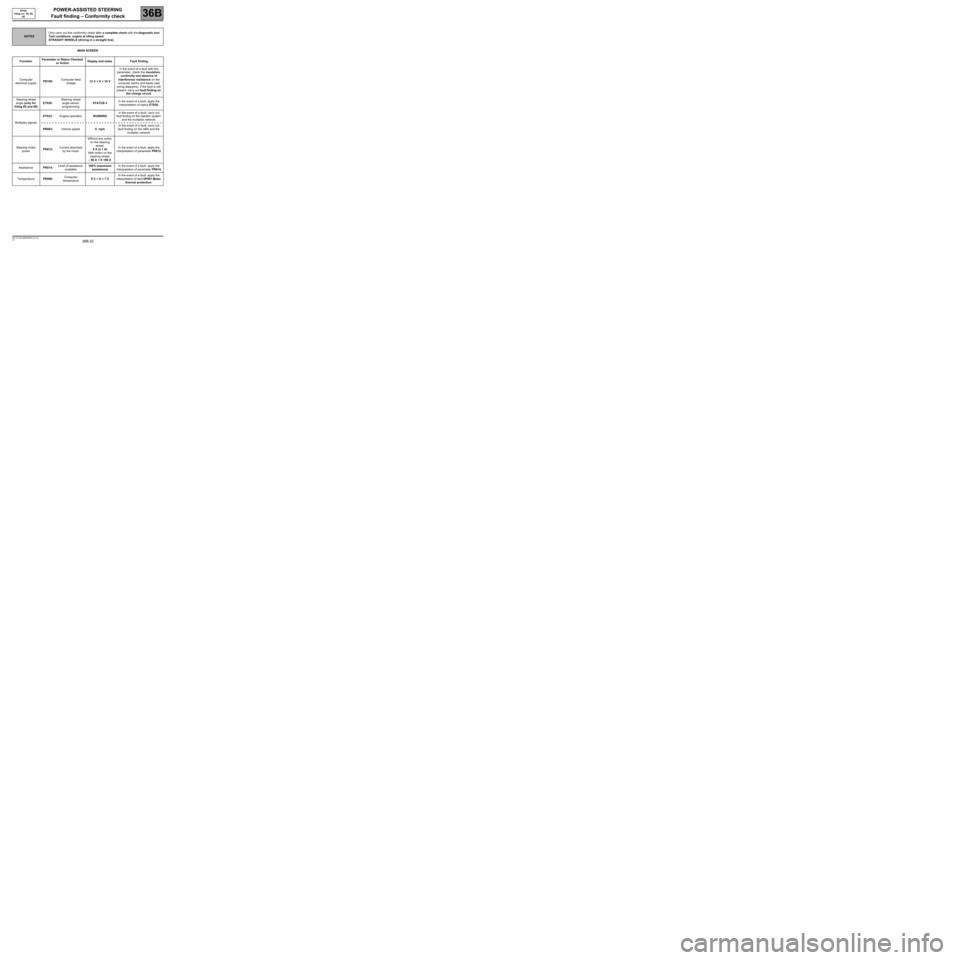
MAIN SCREEN
NOTESOnly carry out this conformity check after a complete check with the diagnostic tool.
Test conditions: engine at idling speed.
STRAIGHT WHEELS (driving in a straight line).
FunctionParameter or Status Checked
or ActionDisplay and notes Fault finding
Computer
electrical supplyPR108:Computer feed
voltage12 V < X < 16 VIn the event of a fault with this
parameter, check the insulation,
continuity and absence of
interference resistance on the
computer earths and feeds (see
wiring diagrams). If the fault is still
present, carry out fault finding on
the charge circuit.
Steering wheel
angle (only for
Vdiag 05 and 09)ET020:Steering wheel
angle sensor
programmingSTATUS 4In the event of a fault, apply the
interpretation of status ET020.
Multiplex signalsET023:Engine operationRUNNINGIn the event of a fault, carry out
fault finding on the injection system
and the multiplex network.
PR003:Vehicle speed0 mphIn the event of a fault, carry out
fault finding on the ABS and the
multiplex network.
Steering motor
powerPR012:Current absorbed
by the motorWithout any action
on the steering
wheel:
0 A (± 1 A)
With action on the
steering wheel:
- 96 A < X <96 AIn the event of a fault, apply the
interpretation of parameter PR012.
AssistancePR014:Level of assistance
available100% (maximum
assistance)In the event of a fault, apply the
interpretation of parameter PR014.
TemperaturePR008:Computer
temperature0˚C < X < 7˚CIn the event of a fault, apply the
interpretation of fault DF001 Motor
thermal protection.
Page 33 of 59
POWER-ASSISTED STEERING
Fault finding – Conformity check
36B
36B-33V5 MR-372-J84-36B000$528_fra.mif
EPAS
Vdiag no.: 05, 09,
0D
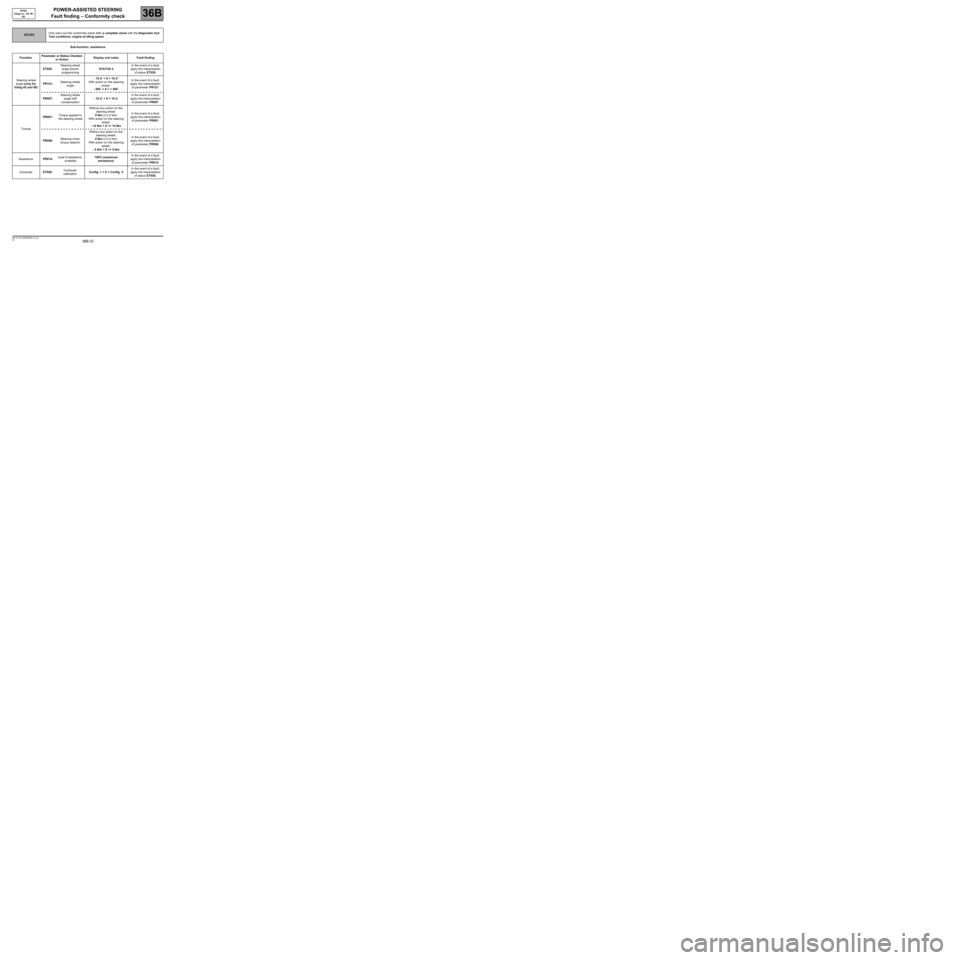
Sub-function: assistance
NOTESOnly carry out this conformity check after a complete check with the diagnostic tool.
Test conditions: engine at idling speed.
FunctionParameter or Status Checked
or ActionDisplay and notes Fault finding
Steering wheel
angle (only for
Vdiag 05 and 09)ET020:Steering wheel
angle sensor
programmingSTATUS 4In the event of a fault,
apply the interpretation
of status ET020.
PR121:Steering wheel
angle- 10 d˚ < X < 10 d˚
With action on the steering
wheel:
- 585˚ < X < + 585˚In the event of a fault,
apply the interpretation
of parameter PR121.
PR007:Steering wheel
angle drift
compensation- 10 d˚ < X < 10 d˚In the event of a fault,
apply the interpretation
of parameter PR007.
TorquePR001:Torque applied to
the steering wheelWithout any action on the
steering wheel:
0 Nm (± 0.2 Nm)
With action on the steering
wheel:
- 14 Nm < X <+ 14 NmIn the event of a fault,
apply the interpretation
of parameter PR001.
PR006:Steering motor
torque setpointWithout any action on the
steering wheel:
0 Nm (± 0.2 Nm)
With action on the steering
wheel:
- 5 Nm < X <+ 5 NmIn the event of a fault,
apply the interpretation
of parameter PR006.
AssistancePR014:Level of assistance
available100% (maximum
assistance)In the event of a fault,
apply the interpretation
of parameter PR014.
ComputerET026:Computer
calibrationConfig. 1 < X < Config. 5In the event of a fault,
apply the interpretation
of status ET026.
Page 36 of 59

POWER-ASSISTED STEERING
Fault finding – Status summary table
36B
36B-36V5 MR-372-J84-36B000$594_fra.mif
EPAS
Vdiag no.: 05, 09,
0DPOWER-ASSISTED STEERING
Fault finding – Status summary table
Tool status Diagnostic tool title
ET020Steering wheel angle sensor programming (only for Vdiag 05 and 09)
ET023Engine operation
ET026Computer calibration
MR-372-J84-36B000$594_fra.mif
Page 37 of 59
POWER-ASSISTED STEERING
Fault finding – Interpretation of statuses
36B
36B-37V5 MR-372-J84-36B000$660_fra.mif
EPAS
Vdiag no.: 05, 09,
0DPOWER-ASSISTED STEERING
Fault finding – Interpretation of statuses
ET020
PROGRAMMING THE STEERING WHEEL ANGLE SENSOR
NOTESSpecial note:
–This status is declared correct when it is STATUS 4 (normal mode); in any other
case, apply this fault finding procedure.
–The SERVICE indicator light will come on if the steering wheel angle calibration has
not been carried out.
VARIOUS POSSIBLE STATUS VALUES (with the meaning):
STATUS 1:
–Straight ahead wheel position not programmed.
–Invalid angle value.
PROGRAMMING NOT COMPLETE.STATUS 3:
–Straight ahead wheel position not programmed.
–Invalid angle value.
–Steering wheel out of range ± 120˚ when after ignition
is switched on.
PROGRAMMING COMPLETE, ANGLE TO BE
CONFIRMED.
STATUS 2:
–Straight ahead wheel position not programmed.
–Invalid angle value.
PROGRAMMING NOT COMPLETE.STATUS 4:
–Straight ahead wheel position not programmed.
–Valid angle value.
PROGRAMMING COMPLETE.
STATUS 1 or STATUS 2
If the status is STATUS 1 or STATUS 2, program the steering wheel angle (see Configuration and
programming).
STATUS 3
If the status is STATUS 3, turn the steering wheel from right lock to left lock then slowly return it to slightly beyond
the centre point (PR135 "Column rotation speed" less than 200˚/s). The status should become STATUS 4.
Note:
A present or stored fault can impede STATUS 4 (carry out the necessary operations by referring to the Fault
Finding Manual).
AFTER REPAIRPerform a test using the diagnostic tool.
DAE_V05_ET020/DAE_V09_ET020/DAE_V0D_ET020
MR-372-J84-36B000$660_fra.mif
Page 41 of 59
POWER-ASSISTED STEERING
Fault finding – Interpretation of parameters
36B
36B-41V5 MR-372-J84-36B000$792_fra.mif
EPAS
Vdiag no.: 05, 09,
0DPOWER-ASSISTED STEERING
Fault finding – Interpretation of parameters
PR001
TORQUE APPLIED TO THE STEERING WHEEL
NOTESNone.
This parameter indicates the torque applied by the driver to the steering column. It is positive when the steering
wheel is turned to the right and negative when it is turned to the left.
If the parameter does not conform with the values indicated in the Conformity check, refer to the interpretation of
fault DF054 Torque sensor.
AFTER REPAIRPerform a test using the diagnostic tool.
DAE_V05_PR001/DAE_V09_PR001/DAE_V0D_PR001
MR-372-J84-36B000$792_fra.mif
Page 43 of 59
POWER-ASSISTED STEERING
Fault finding – Interpretation of parameters
36B
36B-43V5 MR-372-J84-36B000$792_fra.mif
EPAS
Vdiag no.: 05, 09
PR007
STEERING WHEEL ANGLE DRIFT COMPENSATION
NOTESNone.
This parameter shows the correction of the angle value, implemented automatically by the EPAS computer. When
driving, if the steering wheel angle in the straight-ahead driving position is not 0˚, this parameter varies (offset from
the steering wheel angle value).
If the value of the parameter is different to 0 d˚ (± 10 d˚), check the value of parameter PR121 Steering wheel
angle with straight wheels, if PR121 > ± 10 d˚ program the steering wheel angle using command VP004 Steering
wheel sensor programming (see Configuration and programming, section C).
If PR121 < ± 10 d˚ and the vehicle is fitted with ESP, place the vehicle on a geometry test bench (front axle test
bench).. Position the vehicle wheels in the straight line driving position (steering centre point).
Program the steering wheel angle using command VP004 Steering wheel angle sensor programming (see
Configuration and programming).
AFTER REPAIRPerform a test using the diagnostic tool.
DAE_V05_PR007/DAE_V09_PR007
Page 46 of 59
POWER-ASSISTED STEERING
Fault finding – Interpretation of parameters
36B
36B-46V5 MR-372-J84-36B000$792_fra.mif
EPAS
Vdiag no.: 05, 09
PR121
STEERING WHEEL ANGLE
NOTESNone.
This parameter shows the steering wheel position in relation to the programmed zero (performed by command
VP004 "Steering wheel angle sensor programming").
This parameter is positive to the right and negative to the left.
If the angle remains at 3696˚, either:
–the steering wheel angle programming has not been carried out (ET020 Steering wheel angle programming
is STATUS 1 or STATUS 2),
–or the steering wheel is outside the range ± 120 d˚ (ET020 Steering wheel angle programming is STATUS 3),
when the APC is switched on, therefore the angle is valid; the angle is STATUS 4 only if the steering wheel is
within the range ± 120 d˚. As the sensor's coverage is not complete, it needs to come within this zone to detect
its position.
Thus, when the APC is switched on, if the steering wheel is not within the range ± 120 d˚ then the angle is invalid
(ET020 Steering wheel angle programming is STATUS 3). Simply rotating the steering wheel so that it is in the
± 120 d˚ range will allow a valid angle to be found (ET020 Steering wheel angle programming is STATUS 4),
when the EPAS is operating correctly,
–the sensor is faulty DF038 Angle sensor.
If the angle remains at 3696˚, with action on the steering wheel and status ET020 Steering wheel angle
programming is STATUS 4, contact the Techline.
If the parameter does not correspond to the values shown in the Conformity check, place the vehicle on a
geometry test bench (front axle bench). Position the vehicle wheels in the straight line driving position (steering
centre point).
Program the steering wheel angle using command VP004 Steering wheel angle sensor programming (see
Configuration and programming).
AFTER REPAIRPerform a test using the diagnostic tool.
DAE_V05_PR121/DAE_V09_PR121
Page 48 of 59
POWER-ASSISTED STEERING
Fault finding – Fault Finding Chart
36B
36B-48V5 MR-372-J84-36B000$924_fra.mif
EPAS
Vdiag no.: 05, 09,
0DPOWER-ASSISTED STEERING
Fault finding – Fault Finding Chart
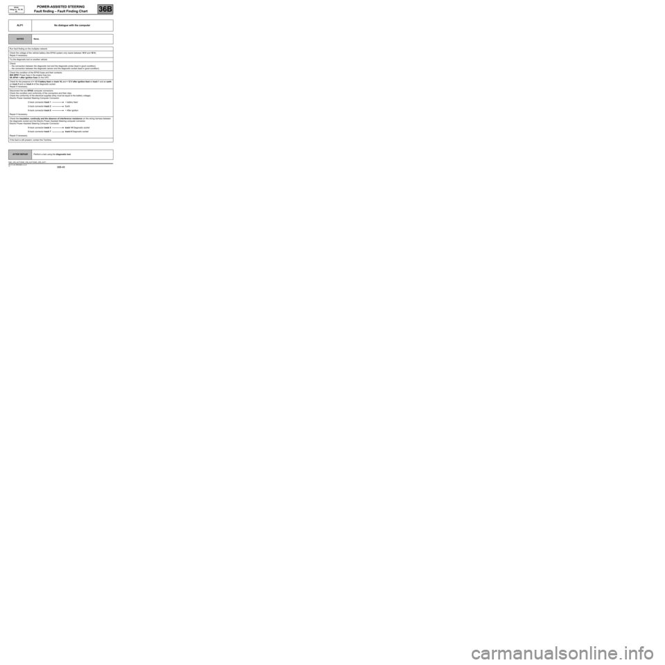
ALP1 No dialogue with the computer
NOTESNone.
Run fault finding on the multiplex network.
Check the voltage of the vehicle battery (the EPAS system only reacts between 10 V and 18 V).
Repair if necessary.
Try the diagnostic tool on another vehicle.
Check:
–the connection between the diagnostic tool and the diagnostic probe (lead in good condition),
–the connection between the diagnostic sensor and the diagnostic socket (lead in good condition).
Check the condition of the EPAS fuses and their contacts:
80A BP81 Power fuse in the engine fuse box.
5A AP44 + after ignition fuse on the UPC.
Check for the presence of + 12 V battery feed on track 16, and + 12 V after ignition feed on track 1 and an earth
on track 5 and on track 4 of the diagnostic socket.
Repair if necessary.
Disconnect the two EPAS computer connectors.
Check the condition and conformity of the connectors and their clips.
Check the conformity of the electrical supplies (they must be equal to the battery voltage).
Electric Power Assisted Steering Computer Connector:
2-track connector track 1+ battery feed
2-track connector track 2Earth
8-track connector track 8+ After ignition
Repair if necessary.
Check the insulation, continuity and the absence of interference resistance on the wiring harness between
the diagnostic socket and the Electric Power Assisted Steering computer connector.
Electric Power Assisted Steering Computer Connector:
8-track connector track 5 track 14 Diagnostic socket
8-track connector track 7 track 6 Diagnostic socket
Repair if necessary.
If the fault is still present, contact the Techline.
AFTER REPAIRPerform a test using the diagnostic tool.
DAE_V05_ALP1/DAE_V09_ALP1/DAE_V0D_ALP1
MR-372-J84-36B000$924_fra.mif