RENAULT SCENIC 2008 J84 / 2.G Electrical Equipment - Network Interface Unit BIC User Guide
Manufacturer: RENAULT, Model Year: 2008, Model line: SCENIC, Model: RENAULT SCENIC 2008 J84 / 2.GPages: 44, PDF Size: 0.16 MB
Page 11 of 44
86D-11V1 MR-372-J84-86D050$040.mif
86D
BIC
Vdiag No.: 14
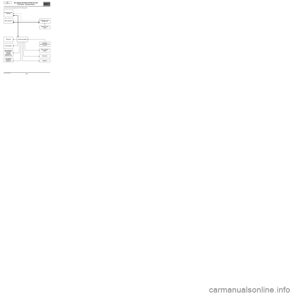
Layout of the main components of the LPN* Radio system:
Diagnostic socket
V M CAN
Other computersMultimedia network
interface unit
Steering column
control
GPS aerial LPN radio navigation
Passenger
compartment fuse box
and relay
Aerial amplifier
Radio navigation
display
ABS, ABS/ESP or
wheel speed
computer
depending on
equipment level
Microphone
CD changer
(depending on
equipment)Speakers
MULTIMEDIA NETWORK INTERFACE UNIT
Fault finding – Operating diagram
Page 12 of 44
86D-12V1 MR-372-J84-86D050$040.mif
MULTIMEDIA NETWORK INTERFACE UNIT
Fault finding – Operating diagram86D
BIC
Vdiag No.: 14
*LPN: Low Price NavigationVehicle multiplex network
Multimedia multiplex network
Page 13 of 44
86D-13V1 MR-372-J84-86D050$050.mif
86D
BIC
Vdiag No.: 14
General operation
The multimedia system is involved in the following functions:
–Radio reception (AM, FM).
–Playing CDs/MP3 CDs/navigation map.
–Guidance and navigation system with colour screen.
–Bluetooth hands-free phone.
The use of this multimedia system allows the customer:
–To select radio stations by using the preselections, the list or manual selection.
–To have an automatically-updated radio list.
–To listen to CDs or MP3 CDs.
–To control the radio using the radio control satellite.
–To change various acoustic parameters (bass, treble, fader, etc.).
–To navigate on a colour screen (visual and audio guidance): for this function the system uses GPS, the vehicle
speed wire information and an internal gyroscope.
–To receive traffic information via RDS-TMC and to display it on the navigation map.
–To display the time and temperature on the screen.
–To use the hands-free phone function (sound relayed to the radio speakers) with a Bluetooth phone (HFP profile).
–To be protected by an immobiliser code.
MULTIMEDIA NETWORK INTERFACE UNIT
Fault finding – Function
Page 14 of 44
86D-14V1 MR-372-J84-86D050$060.mif
86D
BIC
Vdiag No.: 14
SETTINGS
VP001: Write VIN
This command permits manual entry of the vehicle's VIN into the computer. Use this command each time the
computer is replaced. The VIN number is inscribed on the manufacturer's plate.
Procedure for writing the VIN
–Establish dialogue with the navigation computer.
–Select the menu repair mode.
–Select the other parameters menu.
–Select line VP001.
–Enter the VIN.
–Exit fault finding mode.
–Switch off the ignition.
–Wait for the end of the Powerlatch* phase (20 minutes maximum).
–Reread the VIN in the Identification menu for confirmation (ID008 VIN code).
CONFIGURATIONS
CF007: Vehicle configuration
This command is used to configure the computer according to the vehicle type.
LC001 Vehicle type can be used to confirm that the configuration has been properly entered.
Important: After switching on the system, there can be a delay of 20 seconds before dialogue is established.
*Powerlatch: Time required for injection computer supply after + 12 V after ignition feed cut-off.
MULTIMEDIA NETWORK INTERFACE UNIT
Fault finding – Configurations and programming
Page 15 of 44
86D-15V1 MR-372-J84-86D050$070.mif
86D
BIC
Vdiag No.: 14
For information on removing/refitting the multimedia network interface unit, refer to the MR for the vehicle concerned:
–Scénic II Phase 2 (see MR 370, Mechanical, 83C, On-board telematics system, Multimedia network interface
unit: Removal - Refitting)
–Espace IV Phase 2 (see MR 405, Mechanical, 83C, On-board telematics system, Multimedia network
interface unit: Removal - Refitting)
Operations to be carried out before replacing the multimedia network interface unit:
1. Before replacing the multimedia network interface unit (with Techline approval), perform a fault read and a
conformity check to confirm that it is defective.
2. After obtaining Techline approval, remove the multimedia network interface unit, with the ignition off (wait
1 minute for the system to shut down completely).
The multimedia network interface units available from the Parts Department are supplied unconfigured.
Operations to be carried out after replacing the multimedia network interface unit:
–Configure the multimedia network interface unit (see Configurations and Programming).
Important: After switching on the system, there can be a delay of 20 seconds before dialogue is established.
*LPN: Low Price NavigationNote:
If the LPN* radionavigation and the multimedia network interface unit (connection unit) are replaced
simultaneously, the multimedia network interface unit must be configured first (see Configurations and
programming).
MULTIMEDIA NETWORK INTERFACE UNIT
Fault finding – Replacement of components
Page 16 of 44
86D-16V1 MR-372-J84-86D050$080.mif
86D
BIC
Vdiag No.: 14
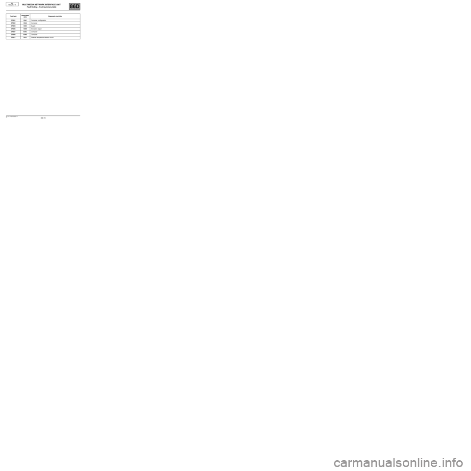
Tool faultAssociated
DTCDiagnostic tool title
DF0019341Computer configuration
DF0029344Computer
DF0059303Supply
DF0069309Activation signal
DF007934CComputer
DF008934DComputer
DF0119331External temperature sensor circuit
MULTIMEDIA NETWORK INTERFACE UNIT
Fault finding – Fault summary table
Page 17 of 44
86D-17
AFTER REPAIRCarry out another fault finding check on the system.
Clear the stored faults using command RZ001 Fault memory.
Deal with any other faults.
V1 MR-372-J84-86D050$090.mif
86D
BIC
Vdiag No.: 14
DF001
PRESENT
OR
STOREDCOMPUTER CONFIGURATION
1.DEF: Blank or incomplete configuration.
NOTESConditions for applying fault finding procedures to stored faults:
The fault is declared present after the multimedia system has been switched on.
Configure the system using configuration CF007 Vehicle configuration (see Configuration and Programming).
If the fault persists, contact your Techline.
BIC_V14_DF001
MULTIMEDIA NETWORK INTERFACE UNIT
Fault finding – Interpretation of faults
Page 18 of 44
86D-18
AFTER REPAIRCarry out another fault finding check on the system.
Clear the stored faults using command RZ001 Fault memory.
Deal with any other faults.
V1 MR-372-J84-86D050$090.mif
MULTIMEDIA NETWORK INTERFACE UNIT
Fault finding – Interpretation of faults86D
BIC
Vdiag No.: 14
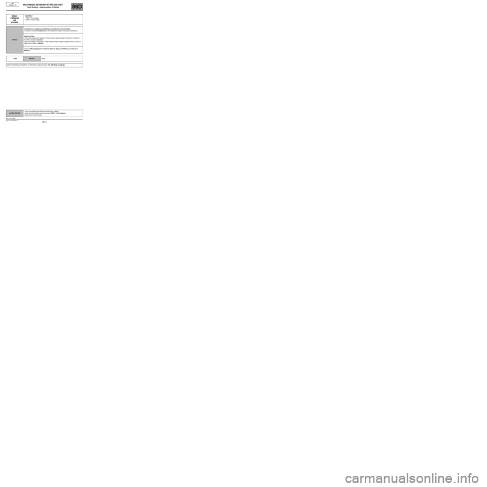
DF002
PRESENT
OR
STOREDCOMPUTER
1.DEF: Internal electronic fault.
NOTESConditions for applying fault finding procedures to stored faults:
The fault is declared present after the multimedia system has been switched on.
Replace the multimedia network interface unit, component code 1714 (see MR 405 (Espace IV Phase 2) or
MR 370 (Scénic II Phase 2) Mechanical, 83C, On-board telematics system, Multimedia network interface
unit: Removal - Refitting).
If the fault persists, contact your Techline.
BIC_V14_DF002
Page 19 of 44
86D-19
AFTER REPAIRCarry out another fault finding check on the system.
Clear the stored faults using command RZ001 Fault memory.
Deal with any other faults.
V1 MR-372-J84-86D050$090.mif
MULTIMEDIA NETWORK INTERFACE UNIT
Fault finding – Interpretation of faults86D
BIC
Vdiag No.: 14
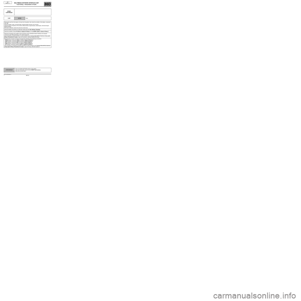
DF005
PRESENT
OR
STOREDSUPPLY
1.DEF: Overvoltage.
2.DEF: Undervoltage.
NOTESConditions for applying fault finding procedures to stored faults:
The fault is declared present after the multimedia system has been switched on.
Special notes:
The undervoltage fault appears if the computer feed voltage is less than or equal to
7.5 V for at least 1 second.
The overvoltage fault appears if the computer feed voltage is greater than or equal to
18.5 V for at least 1 second.
Use the Wiring Diagrams Technical Note for Espace IV Phase 2 or Scénic II
Phase 2.
1.DEF
NOTESNone.
Check the battery and perform an alternator supply test (see 16A, Starting, Charging).
BIC_V14_DF005
Page 20 of 44
86D-20
AFTER REPAIRCarry out another fault finding check on the system.
Clear the stored faults using command RZ001 Fault memory.
Deal with any other faults.
V1 MR-372-J84-86D050$090.mif
MULTIMEDIA NETWORK INTERFACE UNIT
Fault finding – Interpretation of faults86D
BIC
Vdiag No.: 14
DF005
CONTINUED
2.DEFNOTESNone.
Remove the card from the reader or the key from the ignition, then check the condition of the battery, component
code 107.
Check the battery: leaks, incorrectly fitted, loosened battery terminal, and corrosion.
Check the earth connections of the vehicle: battery/chassis, engine/chassis, starter/engine, alternator/engine,
gearbox/chassis.
If the fault is detected, resolve the abnormal contact fault.
Check the battery and perform an alternator supply test (see 16A, Starting, Charging).
Check the condition of fuse F15 (30 A) for Espace IV Phase 2 or fuse SHUNT (2AA) for Scénic II Phase 2.
Check the connection and condition of the connectors of the multimedia network interface unit computer,
component code 1714, depending on the vehicle equipment.
If any connectors are faulty and there is a repair procedure (see Technical Note 6015A, Electrical wiring repair,
Wiring: Precautions for repair), repair the connectors, otherwise replace the wiring.
Disconnect the computer connector and check the conformity of the following connections:
•BP3A between components 260 and 1714 (for Espace IV Phase 2),
•BCP3 between components 260 and 1714 (for Scénic II Phase 2),
•BPT between components 645 and 1714 (for Scénic II Phase 2),
•MAN between component 1714 and earth (for Scénic II Phase 2),
•NC between component 1714 and earth (for Espace IV Phase 2).
If the connection or connections are faulty and there is a repair procedure (see Technical Note 6015A, Electrical
wiring repair, Wiring: Precautions for repair), repair the wiring, otherwise replace it.