RENAULT SCENIC 2008 J84 / 2.G Passenger Comparment Connection Unit Repair Manual
Manufacturer: RENAULT, Model Year: 2008, Model line: SCENIC, Model: RENAULT SCENIC 2008 J84 / 2.GPages: 391
Page 51 of 391
PASSENGER COMPARTMENT CONNECTION UNIT
Fault finding - Configurations and programming
87B
87B-51
PASSENGER COMPARTMENT CONNECTION UNIT
Fault finding - Configurations and programming
87B
87B-51V9 MR-372-J84-87B000$215.mif
UCH
Vdiag No.: 44, 48,
4C, 4D, 4F, 50PASSENGER COMPARTMENT CONNECTION UNIT
Fault finding - Configurations and programming
1/ GENERAL INFORMATION
The engine immobiliser protection system is controlled by a RENAULT card recognition system with random rolling
code.
A coded transponder chip (operating without a battery) independent of the remote control function is built into each
of the vehicle's RENAULT Cards.
The engine immobiliser is active a few seconds after the RENAULT Card is removed from the card reader. Its status
is shown by the flashing warning light on the instrument panel and by locking of the steering column lock.
To obtain the immobiliser code, see Technical Note 5037A, Code delivery procedure.
There are two programming methods: "Not connected" to the code server mode and "connected" to the code
server mode.
–In the "not connected" mode, the CLIP diagnostic tool supplies a programming key and the user enters the
immobiliser code.
–In the "connected" mode, the CLIP diagnostic tool automatically exchanges the programming key and the
immobiliser code.
IMPORTANT
If not all of the Renault cards are available, reallocate all Renault cards later. Cards not inserted will no longer be
allocated to this vehicle.
IMPORTANT
In "not connected" mode, once the tool has issued the programming key, the user has a limited amount of time
in which to enter the immobiliser code.
If this time expires, the CLIP diagnostic tool displays the message "Time expired. Restart the procedure.
Note:
When only the UCH is replaced, there is no operation to perform on the injection computer or the steering column
lock, they retain the same immobiliser code.
IMPORTANT
Once a part is programmed with a code, it is allocated to the vehicle; the code cannot be deleted and the part
cannot be reprogrammed with another code. The programmed code cannot be erased.
IMPORTANT
In "connected" mode, the exchange of the programming key and the entry of the immobiliser code is done
automatically.
If the connection parameters are not met, "connected" mode switches automatically to "not connected" mode.
MR-372-J84-87B000$215.mif
Page 52 of 391
PASSENGER COMPARTMENT CONNECTION UNIT
Fault finding - Configurations and programming
87B
87B-52
PASSENGER COMPARTMENT CONNECTION UNIT
Fault finding - Configurations and programming
87B
87B-52V9 MR-372-J84-87B000$215.mif
UCH
Vdiag No.: 44, 48,
4C, 4D, 4F, 50
2/ UCH PROGRAMMING
The role of this command is to code the UCH.
Use this command only with a new and blank UCH.
A new UCH is not coded and is therefore not assigned to the vehicle; once it is fitted on the vehicle, it must be
programmed to assign it to the vehicle.
To carry out this programming operation, you will need to have:
–a card belonging to the vehicle (allocated to the old UCH).
Before starting this operation, make sure that there are no components capable of interfering with the
electromagnetic field (e.g.: CB (Citizen Band), mobile phone, etc.).
SC004 PROGRAMMING THE UCH
Equipment required
CLIP diagnostic tool
Note:
After an injection computer has been replaced, there are no operations to be performed on the UCH. It retains the
same immobiliser code.
Note:
After only the UCH has been replaced, there are no operations to be performed on the injection computer. The
computers keep the same immobiliser code.
IMPORTANT
When the UCH programming procedure is successfully completed, the UCH is no longer blank and is permanently
assigned to the vehicle. It will not work on another vehicle.
IMPORTANT
When the programming operation is complete, only remove the key once the message Programming complete
is displayed on the screen. Otherwise, programming has failed and the UCH cannot be used.
IMPORTANT
–Do not interrupt the procedure when it is in progress.
–If it is interrupted, restart the procedure; a new programming key will be displayed.
Page 53 of 391
PASSENGER COMPARTMENT CONNECTION UNIT
Fault finding - Configurations and programming
87B
87B-53
PASSENGER COMPARTMENT CONNECTION UNIT
Fault finding - Configurations and programming
87B
87B-53V9 MR-372-J84-87B000$215.mif
UCH
Vdiag No.: 44, 48,
4C, 4D, 4F, 50
UCH programming procedure
–Run the Multiplex network test.
–Switch on the side lights.
–Establish dialogue with the UCH.
–Select the menu repair mode.
–Select the menu secure programming.
–Select line SC004 Program UCH.
Follow the instructions on the CLIP diagnostic tool.
In "not connected" mode, when the CLIP diagnostic tool displays the programming key, make a note of this key
and the VIN.
To obtain the immobiliser code, see Technical Note 5037A, Code delivery procedure.
Operations to be carried out after programming the UCH
●Enter the vehicle VIN in the computer using the command VP004 Enter VIN.
●After programming the UCH, allocate all of the cards using command SC006 Card allocation.
●Configure the equipment as present or not present on the vehicle using the commands
(see Configuration and programming). IMPORTANT
In "not connected" mode, the programming key can only be used for a limited amount of time, as indicated by
the CLIP diagnostic tool. After this time, the programming key and associated immobiliser code are no longer
valid. The operation must be restarted from the beginning.
Page 54 of 391
PASSENGER COMPARTMENT CONNECTION UNIT
Fault finding - Configurations and programming
87B
87B-54
PASSENGER COMPARTMENT CONNECTION UNIT
Fault finding - Configurations and programming
87B
87B-54V9 MR-372-J84-87B000$215.mif
UCH
Vdiag No.: 44, 48,
4C, 4D, 4F, 50
3/ CARD ALLOCATION
–Run the Multiplex network test.
–Establish dialogue with the UCH.
–Select the menu repair mode.
–Select the menu secure programming.
–Confirm line SC006 Card allocation.
The card allocation procedure takes place in two parts:
1Card insertion stage.
2Card allocation stage.
SC006 CARD ALLOCATION
Equipment required
CLIP diagnostic tool
IMPORTANT
The driver's door must remain open throughout the entire card insertion stage.
IMPORTANT
It is not possible to allocate more than two blank cards per operation.
If there are more than 2 blank cards to be allocated: allocate 2 blank cards, then restart the procedure with all the
cards.
IMPORTANT
Only cards which have been ordered for the vehicle concerned or the vehicle's old cards can be inserted.
IMPORTANT
–Do not interrupt the procedure when it is in progress.
–If it is interrupted, restart the procedure; a new programming key will be displayed.
Page 55 of 391

PASSENGER COMPARTMENT CONNECTION UNIT
Fault finding - Configurations and programming
87B
87B-55
PASSENGER COMPARTMENT CONNECTION UNIT
Fault finding - Configurations and programming
87B
87B-55V9 MR-372-J84-87B000$215.mif
UCH
Vdiag No.: 44, 48,
4C, 4D, 4F, 50
Card insertion stage:
The CLIP diagnostic tool requests that the cards to be allocated are inserted.
Insert ALL of the cards to be allocated. Cards which are not inserted at this stage will be rejected in the "card
allocation" stage, and this will mean that the whole operation must be restarted so that the cards which have not been
inserted can then be allocated.
Once all the cards have been inserted, the Clip diagnostic tool displays the programming key.
To obtain the immobiliser code, (see Technical Note 5037A, Code delivery procedure).
Card allocation stage:
Continue the procedure following the instructions on the CLIP diagnostic tool.
–Once the cards have been allocated, make sure that all the cards can lock and start the vehicle.
With this system it is not possible to replace some components, such as the UCH and the Renault card as these parts
are sold blank and uncoded. These components cannot be coded when replaced unless they have the vehicle’s
original code stored.IMPORTANT
In "not connected" mode, the programming key can only be used for a limited amount of time, as indicated by
the CLIP diagnostic tool. After this time, the programming key and associated immobiliser code are no longer
valid. The operation must be restarted from the beginning.
Page 56 of 391

PASSENGER COMPARTMENT CONNECTION UNIT
Fault finding - Configurations and programming
87B
87B-56
PASSENGER COMPARTMENT CONNECTION UNIT
Fault finding - Configurations and programming
87B
87B-56V9 MR-372-J84-87B000$215.mif
UCH
Vdiag No.: 44, 48,
4C, 4D, 4F, 50
4/ INJECTION COMPUTER PROGRAMMING:
A blank injection computer is automatically programmed when + after ignition feed is first activated on the vehicle.
After this, the injection computer has been programmed definitively. The injection computer can no longer be used
on another vehicle.
Programming will operate correctly if:
–the cards and UCH are programmed,
–the steering column lock is programmed (to activate + after ignition feed),
–the injection computer is blank.
Page 57 of 391
PASSENGER COMPARTMENT CONNECTION UNIT
Fault finding - Configurations and programming
87B
87B-57
PASSENGER COMPARTMENT CONNECTION UNIT
Fault finding - Configurations and programming
87B
87B-57V9 MR-372-J84-87B000$215.mif
UCH
Vdiag No.: 44, 48,
4C, 4D, 4F, 50
5/ TYRE PRESSURE MONITORING SYSTEM FUNCTION
5.1 PROGRAMMING PROCEDURE FOR THE 4 VALVE CODES (SC002)
SC002:
Programming the four valve codes
IMPORTANT:
Any operation involving the replacement of a wheel sensor, requires perfect knowledge of the
recommendations defined in Repair Manual 364 (for Mégane II) or 370 (for Scénic II), section 35.
●Inflate the four tyres to 3.8 bar.
●Establish communication with the UCH using the diagnostic tool.
●Select the Repair mode menu.
●Select the Programming menu.
●Select line SC002 in the Tyre function.
●The stored codes and valve sets detected are displayed.
●Select the Valve set selection menu, then Summer or Winter.
●Confirm to display the Valve programming conditions table.
●Confirm by selecting next to obtain the Find valve codes menu.
●Excite each valve by holding the valve exciter against the tyre just below the valve in question.
●Start with the front left-hand wheel.
●Wait for the new code to appear on the screen before moving on to the next valve.
●The order for programming the codes is as follows:
Front left-hand Front right-hand Rear right-hand Rear left-hand
●Click on the "Confirm" button to transmit the codes to the UCH.
●Inflate the tyres to the recommended pressures.
●Carry out a road test: speed > 12 mph (20 km/h) for 10 minutes.
●Check that no message appears on the instrument panel.
IMPORTANT:
When swapping wheels over, reprogram the UCH with the new valve positions using the diagnostic tool and
program the valve codes.
The coloured rings will then have to be placed back in the location marked on the label on the driver's door.
Page 58 of 391
PASSENGER COMPARTMENT CONNECTION UNIT
Fault finding - Configurations and programming
87B
87B-58
PASSENGER COMPARTMENT CONNECTION UNIT
Fault finding - Configurations and programming
87B
87B-58V9 MR-372-J84-87B000$215.mif
UCH
Vdiag No.: 44, 48,
4C, 4D, 4F, 50
5.2 PROCEDURE FOR ENTERING THE RECOMMENDED PRESSURES (VP005)
VP005:
ENTER RECOMMENDED PRESSURES
To enter the recommended pressures correctly, use the values recommended by the manufacturer and found in
the repair manual (MR 364 (Mégane II) or MR 370 (Scénic II), Mechanical, 35A, Tyre pressure: Identification),
or Driver's handbook for the vehicle with the tyres installed on the vehicle or indicated on the label on the
driver's door.
●Select the Repair mode menu.
●Select the Other parameters menu.
●Select line VP005.
●Enter the vehicle type: Extended MPV or other.
●Enter the recommended pressures at the keyboard.
●Confirm the pressures.
●Click on Finish to end the procedure.
●Check the recommended pressures in memory:
●Select the Statuses/Parameters menu.
●Select the Tyre management menu.
●Read the parameters PR009 Front wheels low speed recommended pressure to PR012 Front wheels high
speed recommended pressure.
In the event of any problem occurring, start the operation again from the beginning.
IMPORTANT:
If the recommended pressure format is not correct or if the pressure entered is outside the permitted tolerance
values in relation to the type of vehicle selected, the following error message will be displayed: "Procedure failed:
incorrect pressure format or value outside authorised range".
Page 59 of 391
PASSENGER COMPARTMENT CONNECTION UNIT
Fault finding - Configurations and programming
87B
87B-59
PASSENGER COMPARTMENT CONNECTION UNIT
Fault finding - Configurations and programming
87B
87B-59V9 MR-372-J84-87B000$215.mif
UCH
Vdiag No.: 44, 48,
4C, 4D, 4F, 50
5.3 PROCEDURE FOR READING VALVE SET AND STORED CODES (SC001)
SC001:
READ THE VALVE SET AND STORED CODES
●Select the Repair mode menu.
●Select the Programming menu.
●Select line SC001 in the Tyre function.
Page 60 of 391
PASSENGER COMPARTMENT CONNECTION UNIT
Fault finding - Configurations and programming
87B
87B-60
PASSENGER COMPARTMENT CONNECTION UNIT
Fault finding - Configurations and programming
87B
87B-60V9 MR-372-J84-87B000$215.mif
UCH
Vdiag No.: 44, 48,
4C, 4D, 4F, 50
6/ CHILD SAFETY LOCK CONFIGURATION PROCEDURE (SC016)
This procedure will enable the child safety system, if fitted to the vehicle, to be configured for optimum running
during the replacement of a UCH.
–Click on the Repair mode and in the Programming menu,
–confirm the line SC016 Child safety,
–follow the procedure and enter the following data:
–CF104 Child safety lock (WITH or WITHOUT),
–confirm and follow the procedure,
–finish by confirming and clearing the stored faults. The child safety function is configured.
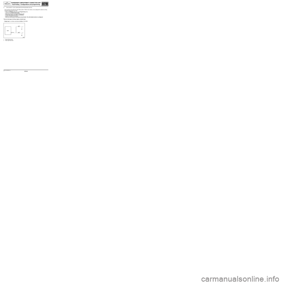
There are two types of wiring: single or double input.
–Single input: on vehicles manufactured before 10/01/2005.
1Rear left-hand door
2Rear right-hand door