sensor RENAULT SCENIC 2008 J84 / 2.G Passenger Comparment Connection Unit Repair Manual
[x] Cancel search | Manufacturer: RENAULT, Model Year: 2008, Model line: SCENIC, Model: RENAULT SCENIC 2008 J84 / 2.GPages: 391
Page 190 of 391
PASSENGER COMPARTMENT CONNECTION UNIT
Fault finding - Interpretation of statuses87B
87B - 190
PASSENGER COMPARTMENT CONNECTION UNIT
Fault finding - Interpretation of statuses87B
87B - 190V9 MR-372-J84-87B000$516.mif
UCH
Vdiag No.: 44, 48,
4C, 4D, 4F, 50
ET073
STEERING COLUMN LOCK SENSOR SIGNAL
NOTESNo faults should be present or stored.
The status should be unlocked with after ignition feed present or semi activated to
+ accessories.
Special note:
Perform locking/unlocking.
Check the power supply to the lock for 5 min after the locking-unlocking operation.
Use Wiring Diagrams Technical Note for MEGANE II or SCENIC II.
ET073 Faulty when the steering column is not unlocked.
ET073 Short circuit when the steering column is not unlocked.
Check the condition and connection of the steering column lock connector (tabs bent, broken, oxidised, etc.).
If the connector is faulty and if there is a repair procedure (see Technical Note 6015A, Repairing electrical
wiring, Wiring: Precautions for repair), repair the connector; otherwise, replace the wiring.
Check the condition and connection of the PE2 connector of the UCH (tabs bent, broken, oxidised, etc.).
If the connector is faulty and if there is a repair procedure (see Technical Note 6015A, Repairing electrical
wiring, Wiring: Precautions for repair), repair the connector; otherwise, replace the wiring.
Check the supply of connection 26I on the connector of component 1088.
If the connector is faulty and if there is a repair procedure (see Technical Note 6015A, Repairing electrical
wiring, Wiring: Precautions for repair), repair the connector; otherwise, replace the wiring.
Check the continuity of connection NAM on the connector of component 1088.
If the connector is faulty and if there is a repair procedure (see Technical Note 6015A, Repairing electrical
wiring, Wiring: Precautions for repair), repair the connector; otherwise, replace the wiring.
Check the insulation and continuity of the following connections:
●Connection code 26AZ,
●Connection code 26BA,
●Connection code 26J of component 1088.
If the connection or connections are faulty and there is a repair procedure (see Technical Note 6015A, Electrical
wiring repair, wiring: precautions for repair), repair the wiring, otherwise replace it.
If the fault is still present, contact Techline.
AFTER REPAIRCarry out another fault finding check on the system.
Clear the stored faults.
Deal with any other faults.
UCH_V44_ET073/UCH_V48_ET073/ UCH_V4C_ET073/
UCH_V4D_ET073 /UCH_V4F_ET073/UCH_V50_ET073
Page 191 of 391
PASSENGER COMPARTMENT CONNECTION UNIT
Fault finding - Interpretation of statuses87B
87B - 191
PASSENGER COMPARTMENT CONNECTION UNIT
Fault finding - Interpretation of statuses87B
87B - 191V9 MR-372-J84-87B000$516.mif
UCH
Vdiag No.: 44, 48,
4C, 4D, 4F, 50
ET073
CONTINUED
ET073 Unlocked and + after ignition absent.
The status remains UNLOCKED, with the ignition off, in case of failure of the airbag system or the speed signal. If
everything is OK, see dealing with fault DF029: Steering column lock circuit.
ET073 Semi-activated and + after ignition present.
In the semi-activated status, the lock bolt is pulled out, but the UCH cannot determine its position precisely.
In case of inconsistency, contact the Techline.
ET073 Undetermined.
The status is Undetermined. in the event that neither the steering column lock nor the lock sensor can inform the
UCH regarding its position.
Refer to processing of the DF029 Steering column lock circuit fault.
AFTER REPAIRCarry out another fault finding check on the system.
Clear the stored faults.
Deal with any other faults.
Page 232 of 391
PASSENGER COMPARTMENT CONNECTION UNIT
Fault finding - Interpretation of statuses87B
87B - 232
PASSENGER COMPARTMENT CONNECTION UNIT
Fault finding - Interpretation of statuses87B
87B - 232V9 MR-372-J84-87B000$559.mif
UCH
Vdiag No.: 44, 48,
4C, 4D, 4F, 50
ET114
WIPER REQUEST BY RAIN SENSOR
NOTESNo faults should be present or stored.
Make sure that the vehicle is fitted with the rain and light sensor.
The status should change to ACTIVE if there is any water on the windscreen on the
sensor position.
Make sure that the other positions of the wiper control are working properly.
Use Wiring Diagrams Technical Note for MEGANE II or SCENIC II.
Check the condition and connection of the rain and light sensor connector (tabs broken, bent, oxidised).
If the connector is faulty and if there is a repair procedure (see Technical Note 6015A, Repairing electrical
wiring, Wiring: Precautions for repair), repair the connector; otherwise, replace the wiring.
Check the + 12 V APC on connection BPT of component 1415.
If the connector is faulty and if there is a repair procedure (see Technical Note 6015A, Repairing electrical
wiring, Wiring: Precautions for repair), repair the connector; otherwise, replace the wiring.
If the + 12 V feed is not correct, check the insulation, continuity and the absence of interference resistance
of the following connection:
●Connection code BPT between components 645 and 1415.
If the connection is faulty and there is a repair procedure (see Technical Note 6015A, Electrical wiring repair,
Wiring: Precautions for repair), repair the wiring, otherwise replace it.
If the + 12 V feed is not correct for vehicles manufactured after June 2005, check the insulation, continuity and
the absence of interference resistance on the following connection:
●Connection code BPT between component 645 and fuse F5F (7.5A) (on the Protection and Switching
Unit).
Check for earth on the MAM connection of component 1415.
If the connector is faulty and if there is a repair procedure (see Technical Note 6015A, Repairing electrical
wiring, Wiring: Precautions for repair), repair the connector; otherwise, replace the wiring.
Check the condition and connection of the UCH connector (tabs broken, bent, oxidised).
If the connector is faulty and if there is a repair procedure (see Technical Note 6015A, Repairing electrical
wiring, Wiring: Precautions for repair), repair the connector; otherwise, replace the wiring.
Check the insulation, continuity and the absence of interference resistance on the following connection:
●Connection code 14S between components 645 and 1415.
If the connection is faulty and there is a repair procedure (see Technical Note 6015A, Electrical wiring repair,
Wiring: Precautions for repair), repair the wiring, otherwise replace it.
Check configuration LC044 Rain/light sensor.
If the fault is still present, contact Techline.
AFTER REPAIRCarry out another fault finding check on the system.
Clear the stored faults.
Deal with any other faults.
UCH_V44_ET114/UCH_V48_ET114/UCH_V4C_ET114/
UCH_V4D_ET114/UCH_V4F_ET114/UCH_V50_ET114
Page 233 of 391
PASSENGER COMPARTMENT CONNECTION UNIT
Fault finding - Interpretation of statuses87B
87B - 233
PASSENGER COMPARTMENT CONNECTION UNIT
Fault finding - Interpretation of statuses87B
87B - 233V9 MR-372-J84-87B000$559.mif
UCH
Vdiag No.: 44, 48,
4C, 4D, 4F, 50
ET115
REQUEST FROM LIGHT SENSOR TO SWITCH ON HEADLIGHTS
NOTESNo faults should be present or stored.
Make sure that the vehicle is fitted with the rain and light sensor.
The status should change to ACTIVE when the sensor is hidden from the surrounding
light by placing a thumb over it or in darkness.
Make sure that the other lighting control positions are working properly.
Use Wiring Diagrams Technical Note for MEGANE II or SCENIC II.
Check the condition and connection of the rain and light sensor connector (tabs broken, bent, oxidised).
If the connector is faulty and if there is a repair procedure (see Technical Note 6015A, Repairing electrical
wiring, Wiring: Precautions for repair), repair the connector; otherwise, replace the wiring.
Check the + 12 V APC on connection BPT of component 1415.
If the connector is faulty and if there is a repair procedure (see Technical Note 6015A, Repairing electrical
wiring, Wiring: Precautions for repair), repair the connector; otherwise, replace the wiring.
If the + 12 V feed is not correct, check the insulation, continuity and the absence of interference resistance
of the following connection:
●Connection code BPT between components 645 and 1415.
If the connection is faulty and there is a repair procedure (see Technical Note 6015A, Electrical wiring repair,
Wiring: Precautions for repair), repair the wiring, otherwise replace it.
If the + 12 V feed is not correct for vehicles manufactured after June 2005, check the insulation, continuity and
the absence of interference resistance on the following connection:
●Connection code BPT between component 645 and fuse F5F (7.5A) (on the Protection and Switching
Unit).
If the connection is faulty and there is a repair procedure (see Technical Note 6015A, Electrical wiring repair,
Wiring: Precautions for repair), repair the wiring, otherwise replace it.
AFTER REPAIRCarry out another fault finding check on the system.
Clear the stored faults.
Deal with any other faults.
UCH_V44_ET115/UCH_V48_ET115/UCH_V4C_ET115/
UCH_V4D_ET115/UCH_V4F_ET115/UCH_V50_ET115
Page 234 of 391

PASSENGER COMPARTMENT CONNECTION UNIT
Fault finding - Interpretation of statuses87B
87B - 234
PASSENGER COMPARTMENT CONNECTION UNIT
Fault finding - Interpretation of statuses87B
87B - 234V9 MR-372-J84-87B000$559.mif
UCH
Vdiag No.: 44, 48,
4C, 4D, 4F, 50
ET115
CONTINUED
Check for earth on the MAM connection of component 1415.
If the connector is faulty and if there is a repair procedure (see Technical Note 6015A, Repairing electrical
wiring, Wiring: Precautions for repair), repair the connector; otherwise, replace the wiring.
Check the condition and connection of the UCH connector (tabs broken, bent, oxidised).
If the connector is faulty and if there is a repair procedure (see Technical Note 6015A, Repairing electrical
wiring, Wiring: Precautions for repair), repair the connector; otherwise, replace the wiring.
Check the insulation, continuity and the absence of interference resistance on the following connection:
●Connection code 14S between components 645 and 1415.
If the connection is faulty and there is a repair procedure (see Technical Note 6015A, Electrical wiring repair,
Wiring: Precautions for repair), repair the wiring, otherwise replace it.
Check configuration LC044 Rain/light sensor.
If the fault is still present, contact Techline.
AFTER REPAIRCarry out another fault finding check on the system.
Clear the stored faults.
Deal with any other faults.
Page 242 of 391
PASSENGER COMPARTMENT CONNECTION UNIT
Fault finding - Interpretation of parameters
87B
87B -242
PASSENGER COMPARTMENT CONNECTION UNIT
Fault finding - Interpretation of parameters
87B
87B -242V9 MR-372-J84-87B000$688.mif
UCH
Vdiag No.: 44, 48,
4C, 4D, 4F, 50
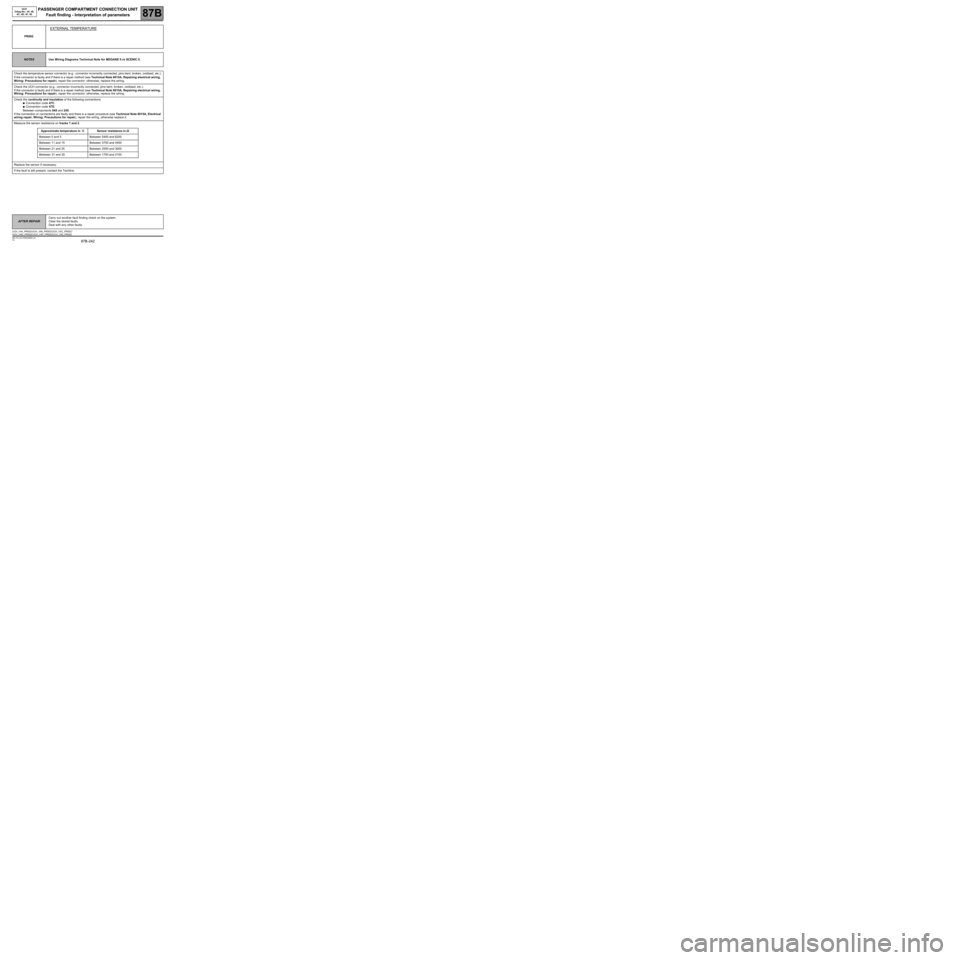
PR002
EXTERNAL TEMPERATURE
NOTESUse Wiring Diagrams Technical Note for MEGANE II or SCENIC II.
Check the temperature sensor connector (e.g.: connector incorrectly connected, pins bent, broken, oxidised, etc.).
If the connector is faulty and if there is a repair method (see Technical Note 6015A, Repairing electrical wiring,
Wiring: Precautions for repair), repair the connector; otherwise, replace the wiring.
Check the UCH connector (e.g.: connector incorrectly connected, pins bent, broken, oxidised, etc.).
If the connector is faulty and if there is a repair method (see Technical Note 6015A, Repairing electrical wiring,
Wiring: Precautions for repair), repair the connector; otherwise, replace the wiring.
Check the continuity and insulation of the following connections:
●Connection code 47C.
●Connection code 47D.
Between components 645 and 245.
If the connection or connections are faulty and there is a repair procedure (see Technical Note 6015A, Electrical
wiring repair, Wiring: Precautions for repair), repair the wiring, otherwise replace it.
Measure the sensor resistance on tracks 1 and 2.
Approximate temperature in ˚CSensor resistance in ΩΩ Ω Ω
Between 0 and 5 Between 5400 and 6200
Between 11 and 15 Between 3700 and 4400
Between 21 and 25 Between 2500 and 3000
Between 31 and 35 Between 1700 and 2100
Replace the sensor if necessary.
If the fault is still present, contact the Techline.
AFTER REPAIRCarry out another fault finding check on the system.
Clear the stored faults.
Deal with any other faults.
UCH_V44_PR002/UCH_V48_PR002/UCH_V4C_PR002 /
UCH_V4D_PR002/ UCH_V4F_PR002/UCH_V50_PR002
Page 243 of 391

PASSENGER COMPARTMENT CONNECTION UNIT
Fault finding - Interpretation of parameters
87B
87B -243
PASSENGER COMPARTMENT CONNECTION UNIT
Fault finding - Interpretation of parameters
87B
87B -243V9 MR-372-J84-87B000$688.mif
UCH
Vdiag No.: 44, 48,
4C, 4D, 4F, 50
PR003
PR004
PR005
PR006FRONT LEFT-HAND WHEEL TYRE PRESSURE
FRONT RIGHT-HAND WHEEL TYRE PRESSURE
REAR RIGHT-HAND WHEEL TYRE PRESSURE
REAR LEFT-HAND WHEEL TYRE PRESSURE
NOTESThere must be no faults present.
Carry out this fault finding procedure after detecting a discrepancy in the parameter
displays.
When communication is established, the default value of the parameters is displayed (0 bar). By creating
a leak or using a road test, force each valve to transmit to discover the actual pressure levels measured
by the sensors during the fault finding procedure.
In all cases, compare whether the pressures displayed on the diagnostic tool correctly match the readings on the
pressure gauge (to within 0.2 bar).
If the readings do not correspond, you may encounter two possible scenarios:
1st case: The parameters still display 0 bar.
This means that the wheel valve codes do not correspond to the wheel set programmed into the UCH. (When the
UCH receives the valve codes, it will not recognise them because they do not correspond to the wheel set codes
already programmed, which are the only ones it will recognise). To rectify this:
Start the programming procedure using command SC002 Program the 4 valve codes (see Configurations and
programming).
2nd case: Parameters PR003 to PR006 display incorrect values (other than 0 bar).
If the pressures differ, there is a fault on the valve. Replace the faulty valve. Follow programming procedure: SC002
(see Configurations and programming).
After programming, repeat the fault finding procedure from the beginning.
AFTER REPAIRRepeat the check from the start.
UCH_V44_PR003/UCH_V48_PR003/UCH_V4C_PR003/UCH_V4D_PR003/UCH_V4F_PR003/UCH_V50_PR003/UCH_V44_PR004/
UCH_V48_PR004/UCH_V4C_PR004/UCH_V4D_PR004/UCH_V4F_PR004/UCH_V50_PR004/UCH_V44_PR005/UCH_V48_PR005/
UCH_V4C_PR005/UCH_V4D_PR005/UCH_V4F_PR005/UCH_V50_PR005/UCH_V44_PR006/UCH_V48_PR006/UCH_V4C_PR006/
UCH_V4D_PR006/UCH_V4F_PR006/UCH_V50_PR006
Page 299 of 391
PASSENGER COMPARTMENT CONNECTION UNIT
Fault finding - Customer complaints
87B
87B -299
PASSENGER COMPARTMENT CONNECTION UNIT
Fault finding - Customer complaints
87B
87B -299V9 MR-372-J84-87B000$860.mif
UCH
Vdiag No.: 44, 48,
4C, 4D, 4F, 50
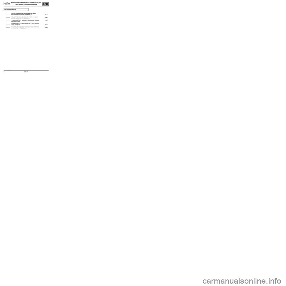
TYRE PRESSURE MONITOR
"ADJUST TYRE PRESSURE" MESSAGE APPEARS (WHEEL
CONCERNED IS HIGHLIGHTED ON THE DISPLAY)ALP52
"ADJUST TYRE PRESSURE" MESSAGE APPEARS (2 WHEELS
BECOME HIGHLIGHTED ON THE DISPLAY)ALP53
"TYRE SENSOR FAULT" MESSAGE APPEARS (WHEEL WARNING
LIGHT DISAPPEARS)ALP54
"TYRE SENSOR FAULT" MESSAGE APPEARS (4 WHEEL WARNING
LIGHTS DISAPPEAR)ALP55
"PUNCTURE: CHANGE WHEEL" MESSAGE APPEARS (THE WHEEL
IS HIGHLIGHTED ON THE DISPLAY)ALP56
Page 352 of 391
PASSENGER COMPARTMENT CONNECTION UNIT
Fault finding - Fault Finding Chart87B
87B - 352
PASSENGER COMPARTMENT CONNECTION UNIT
Fault finding - Fault Finding Chart87B
87B - 352V9 MR-372-J84-87B000$946.mif
UCH
Vdiag No.: 44, 48,
4C, 4D, 4F, 50
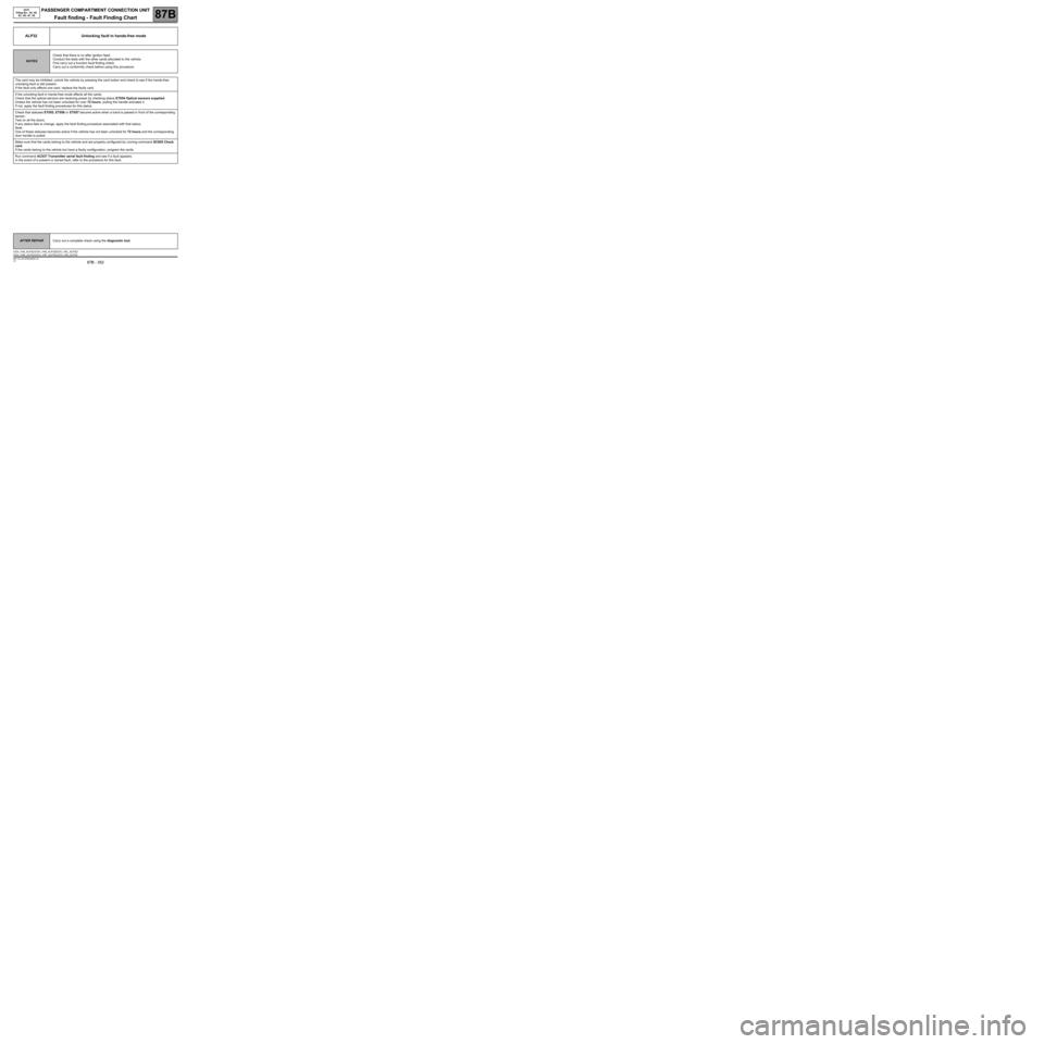
ALP32 Unlocking fault in hands-free mode
NOTESCheck that there is no after ignition feed.
Conduct the tests with the other cards allocated to the vehicle.
First carry out a function fault finding check.
Carry out a conformity check before using this procedure.
The card may be inhibited: unlock the vehicle by pressing the card button and check to see if the hands-free
unlocking fault is still present.
If the fault only affects one card, replace the faulty card.
If the unlocking fault in hands-free mode affects all the cards:
Check that the optical sensors are receiving power by checking status ET054 Optical sensors supplied.
Unless the vehicle has not been unlocked for over 72 hours, pulling the handle activates it.
If not, apply the fault finding procedures for this status.
Check that statuses ET055, ET056 or ET057 become active when a hand is passed in front of the corresponding
sensor.
Test on all the doors.
If any status fails to change, apply the fault finding procedure associated with that status.
Note:
One of these statuses becomes active if the vehicle has not been unlocked for 72 hours and the corresponding
door handle is pulled.
Make sure that the cards belong to the vehicle and are properly configured by running command SC005 Check
card.
If the cards belong to the vehicle but have a faulty configuration, program the cards.
Run command AC037 Transmitter aerial fault finding and see if a fault appears.
In the event of a present or stored fault, refer to the procedure for this fault.
AFTER REPAIRCarry out a complete check using the diagnostic tool.
UCH_V44_ALP32 /UCH_V48_ALP32/UCH_V4C_ALP32/
UCH_V4D_ALP32/UCH_V4F_ALP32/UCH_V50_ALP32
Page 365 of 391
PASSENGER COMPARTMENT CONNECTION UNIT
Fault finding - Fault Finding Chart
87B
87B -365
PASSENGER COMPARTMENT CONNECTION UNIT
Fault finding - Fault Finding Chart
87B
87B -365V9 MR-372-J84-87B000$989mif
UCH
Vdiag No.: 44, 48,
4C, 4D, 4F, 50
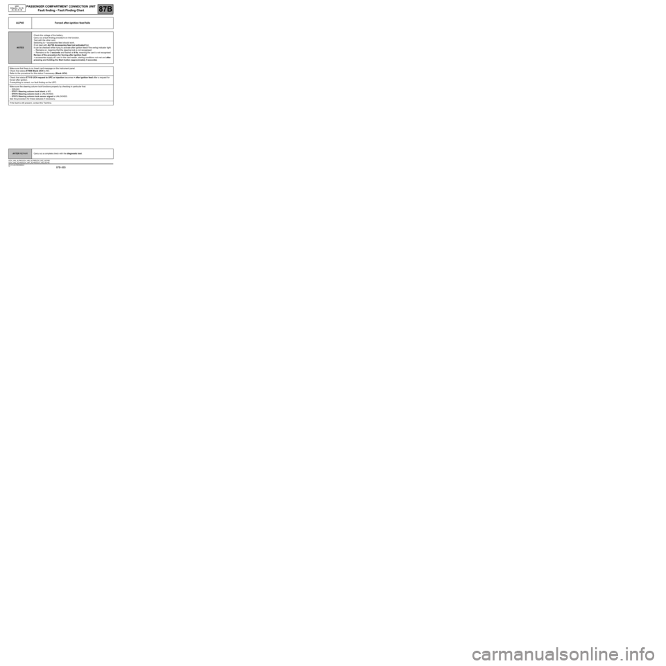
ALP40 Forced after-ignition feed fails
NOTESCheck the voltage of the battery.
Carry out a fault finding procedure on the function.
Test with the other card.
Switching to + accessories feed should work.
If not deal with ALP39 Accessories feed not activated first.
It can be checked while trying to activate after ignition feed if the verlog indicator light:
–Remains on, meaning that the steering lock is not recognised.
–Remains on for 3 seconds and flashes at 4 Hz, meaning the card is not recognised.
Review of the procedure for forcing after ignition feed:
+ accessories supply off, card in the card reader, starting conditions not met and after
pressing and holding the Start button (approximately 5 seconds).
Make sure that there is no Insert card message on the instrument panel.
Check that status ET008 Blank UCH is NO.
Refer to the procedure for this status if necessary (Blank UCH).
Check that status ET110 UCH request to UPC or injection becomes + after ignition feed after a request for
forced after ignition.
If everything is correct, run fault finding on the UPC.
Make sure the steering column lock functions properly by checking in particular that:
–statuses:
–ET071 Steering column lock blank is NO.
–ET072 Steering column lock is UNLOCKED.
–ET073 Steering column lock sensor signal is UNLOCKED.
See the procedure for these statuses if necessary.
If the fault is still present, contact the Techline.
AFTER REPAIRCarry out a complete check with the diagnostic tool.
UCH_V44_ALP40 /UCH_V48_ALP40/UCH_V4C_ALP40/
UCH_V4D_ALP40/UCH_V4F_ALP40/UCH_V50_ALP40